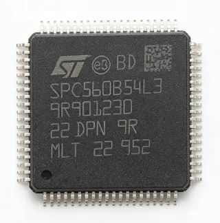
MC56F84587VLL - 32-bit DSC, 256KB Flash, 80MHz | NXP Semiconductors
MPN: MC56F84587VLL ✓ Active| Qty | Unit Price | Extended |
|---|---|---|
| 1 | $12.47 | $12.47 |
| 10 | $11.85 | $118.50 |
| 100 | $10.95 | $1,095.00 |
| 500 | $9.85 | $4,925.00 |
| 1,000 | $9.2 | $9,200.00 |
MC56F84587VLL Overview
A Digital Signal Controller (DSC) is a hybrid between a microcontroller (MCU) and a digital signal processor (DSP). The DSC sits within the broader hierarchy of embedded processors and controllers -> microcontrollers/microprocessors, but adds dedicated MAC (multiply-accumulate) units, single-cycle hardware loops, and tightly-coupled DSP peripherals that allow deterministic execution of control loops and signal processing in parallel with general-purpose tasks. The 56800EX core used here extends this model with up to 80 MHz operation, single-cycle 32-bit math, and integrated interrupt-driven control logic.
Key features include up to 256 KB of program Flash, high-speed analog peripherals suited to digital power conversion, PWM channels and timers tuned for motor control loops, 3.3 V core operation, and the LQFP-100 package providing 100 I/O pins in a footprint compatible with industrial SMT assembly. The device also integrates peripherals commonly required in digital power and motor control designs, including 12-bit ADCs with fast conversion rates, high-resolution PWM modules, and quadrature decoder interfaces for sensor feedback.
Typical applications targeted by the MC56F84587 family include AC/DC and DC/DC digital power converters, solar micro-inverters and string inverters, variable-frequency drives (VFD) for industrial motors, servo drives, brushless DC motor controllers, and uninterruptible power supplies. The combination of DSP-class math throughput and MCU-style peripheral integration makes the device a strong fit for closed-loop control applications where deterministic response time is critical.
When designing with this device, ensure adequate decoupling at the 3.3 V supply pins and proper PCB layout for the high-frequency PWM signals to minimize EMI. The 100-pin LQFP package provides ample I/O for multi-phase power converter designs but requires careful thermal management when driving high-current switching stages.
This page synthesizes distributor pricing, drop-in alternatives, and practical design notes not found in the manufacturer datasheet, including a parameter-by-parameter comparison against same-family variants and cross-brand equivalents.
Drop-in alternatives for MC56F84587VLL — same package, pin-to-pin compatible. Different-package parts requiring PCB rework are excluded.
Variants in this series
Same-series models that are drop-in compatible with MC56F84587VLL (same form factor and footprint) — differing in Core Architecture, Mounting Type, RoHS Status, Communication Interfaces, Package.
Quick Comparison Tool — Select alternative parts for side-by-side comparison:
MC56F84585VLK
✅ Drop-In✓ In Stock
$5.3 / Unit
View Datasheet →MC56F8357VVFE
✅ Drop-In✓ In Stock
$8.36 / Unit
View Datasheet →MC56F8347VVFE
✅ Drop-In✓ In Stock
$17.9 / Unit
View Datasheet →MC56F8355MFGE
✅ Drop-In✓ In Stock
$15.7 / Unit
View Datasheet →MC56F84587VLL Maximum Ratings & Electrical Characteristics
| Core Architecture | 56800EX (32-bit DSP/MCU hybrid) |
| CPU Maximum Frequency | 80 MHz |
| Program Memory (Flash) | 256 KB |
| Supply Voltage | 3.3 V |
| Package Type | LQFP-100 |
| Pin Count | 100 |
| Mounting Type | Surface Mount |
| RoHS Status | Compliant |
| Lead-Free | Yes |
| Temperature Grade | Industrial |
| Terminal Form | Gull Wing |
MC56F84587VLL Pin Configuration
| Pin 1 | VREFH — ADC high reference voltage |
| Pin 2 | VREFL — ADC low reference voltage |
| Pin 3 | ANA0 — Analog input channel 0 |
| Pin 4 | ANA1 — Analog input channel 1 |
| Pin 5 | ANA2 — Analog input channel 2 |
| Pin 6 | ANA3 — Analog input channel 3 |
| Pin 7 | ANA4 — Analog input channel 4 |
| Pin 8 | ANA5 — Analog input channel 5 |
| Pin 9 | ANA6 — Analog input channel 6 |
| Pin 10 | ANA7 — Analog input channel 7 |
| Pin 11 | VDDA — Analog supply voltage |
| Pin 12 | VSSA — Analog ground |
| Pin 13 | XTAL — Crystal oscillator input |
| Pin 14 | EXTAL — External clock input |
| Pin 15 | VDD — Digital supply voltage (3.3V) |
| Pin 16 | VSS — Digital ground |
| Pin 17 | RESET — Reset input (active low) |
| Pin 18 | GPIOB0 — General purpose I/O B0 |
| Pin 19 | GPIOB1 — General purpose I/O B1 |
| Pin 20 | GPIOB2 — General purpose I/O B2 |
| Pin 21 | GPIOB3 — General purpose I/O B3 |
| Pin 22 | PWM0A — PWM channel 0 output A |
| Pin 23 | PWM0B — PWM channel 0 output B |
| Pin 24 | PWM1A — PWM channel 1 output A |
| Pin 25 | PWM1B — PWM channel 1 output B |
| Pin 26 | PWM2A — PWM channel 2 output A |
| Pin 27 | PWM2B — PWM channel 2 output B |
| Pin 28 | PWM3A — PWM channel 3 output A |
| Pin 29 | PWM3B — PWM channel 3 output B |
| Pin 30 | TCK — JTAG test clock |
| Pin 31 | TMS — JTAG test mode select |
| Pin 32 | TDI — JTAG test data input |
| Pin 33 | TDO — JTAG test data output |
| Pin 34 | VDD — Digital supply voltage (3.3V) |
| Pin 35 | VSS — Digital ground |
| Pin 36 | GPIOA0 — General purpose I/O A0 |
| Pin 37 | GPIOA1 — General purpose I/O A1 |
| Pin 38 | GPIOA2 — General purpose I/O A2 |
| Pin 39 | GPIOA3 — General purpose I/O A3 |
| Pin 40 | GPIOA4 — General purpose I/O A4 |
| Pin 41 | GPIOA5 — General purpose I/O A5 |
| Pin 42 | GPIOA6 — General purpose I/O A6 |
| Pin 43 | GPIOA7 — General purpose I/O A7 |
| Pin 44 | GPIOC0 — General purpose I/O C0 |
| Pin 45 | GPIOC1 — General purpose I/O C1 |
| Pin 46 | GPIOC2 — General purpose I/O C2 |
| Pin 47 | GPIOC3 — General purpose I/O C3 |
| Pin 48 | GPIOC4 — General purpose I/O C4 |
| Pin 49 | GPIOC5 — General purpose I/O C5 |
| Pin 50 | GPIOC6 — General purpose I/O C6 |
| Pin 51 | GPIOC7 — General purpose I/O C7 |
| Pin 52 | VDD — Digital supply voltage (3.3V) |
| Pin 53 | VSS — Digital ground |
| Pin 54 | GPIOD0 — General purpose I/O D0 |
| Pin 55 | GPIOD1 — General purpose I/O D1 |
| Pin 56 | GPIOD2 — General purpose I/O D2 |
| Pin 57 | GPIOD3 — General purpose I/O D3 |
| Pin 58 | TXD0 — UART0 transmit data |
| Pin 59 | RXD0 — UART0 receive data |
| Pin 60 | TXD1 — UART1 transmit data |
| Pin 61 | RXD1 — UART1 receive data |
| Pin 62 | MOSI0 — SPI0 master out slave in |
| Pin 63 | MISO0 — SPI0 master in slave out |
| Pin 64 | SCLK0 — SPI0 serial clock |
| Pin 65 | SS0 — SPI0 slave select |
| Pin 66 | SDA0 — I2C0 serial data |
| Pin 67 | SCL0 — I2C0 serial clock |
| Pin 68 | CAN_TX — CAN transmit |
| Pin 69 | CAN_RX — CAN receive |
| Pin 70 | VDD — Digital supply voltage (3.3V) |
| Pin 71 | VSS — Digital ground |
| Pin 72 | PWMA_FLT — PWM fault input |
| Pin 73 | PWM4A — PWM channel 4 output A |
| Pin 74 | PWM4B — PWM channel 4 output B |
| Pin 75 | PWM5A — PWM channel 5 output A |
| Pin 76 | PWM5B — PWM channel 5 output B |
| Pin 77 | PWMSYNC — PWM synchronization input |
| Pin 78 | QUAD_A — Quadrature decoder input A |
| Pin 79 | QUAD_B — Quadrature decoder input B |
| Pin 80 | QUAD_I — Quadrature decoder index |
| Pin 81 | VDD — Digital supply voltage (3.3V) |
| Pin 82 | VSS — Digital ground |
| Pin 83 | GPIOA8 — General purpose I/O A8 |
| Pin 84 | GPIOA9 — General purpose I/O A9 |
| Pin 85 | GPIOA10 — General purpose I/O A10 |
| Pin 86 | GPIOA11 — General purpose I/O A11 |
| Pin 87 | GPIOB4 — General purpose I/O B4 |
| Pin 88 | GPIOB5 — General purpose I/O B5 |
| Pin 89 | GPIOB6 — General purpose I/O B6 |
| Pin 90 | GPIOB7 — General purpose I/O B7 |
| Pin 91 | GPIOE0 — General purpose I/O E0 |
| Pin 92 | GPIOE1 — General purpose I/O E1 |
| Pin 93 | GPIOE2 — General purpose I/O E2 |
| Pin 94 | GPIOE3 — General purpose I/O E3 |
| Pin 95 | GPIOF0 — General purpose I/O F0 |
| Pin 96 | GPIOF1 — General purpose I/O F1 |
| Pin 97 | GPIOF2 — General purpose I/O F2 |
| Pin 98 | GPIOF3 — General purpose I/O F3 |
| Pin 99 | VDD — Digital supply voltage (3.3V) |
| Pin 100 | VSS — Digital ground |
Typical Applications
MC56F84587VLL is suitable for 7 applications: Digital Power Conversion (AC/DC, DC/DC), Variable Frequency Drives (VFD) and Servo Drives, Solar Micro-Inverters and String Inverters, Brushless DC (BLDC) Motor Controllers, Uninterruptible Power Supplies (UPS), Industrial Servo and Robotics, Power Factor Correction (PFC) Stages.
Digital Power Conversion (AC/DC, DC/DC)
The MC56F84587VLL is a strong fit for digital power conversion stages including AC/DC and DC/DC converters. The 80 MHz 56800EX core executes field-oriented control loops, average-current-mode control, and digital PID compensators at the high switching frequencies required by modern SiC and GaN power stages. Integrated 12-bit ADCs sample input voltage and inductor current at sub-microsecond rates, while high-resolution PWM modules generate the timing-critical gate drive waveforms. The 256 KB Flash stores control firmware plus telemetry and PMBus protocol stacks. The LQFP-100 package exposes enough PWM outputs and analog inputs for multi-phase interleaved PFC and LLC converter designs.
Recommended
Variable Frequency Drives (VFD) and Servo Drives
For variable-frequency drives and servo drives, the MC56F84587VLL provides the DSP-class math and deterministic interrupt response needed for field-oriented control (FOC) of three-phase AC induction and permanent-magnet synchronous motors. The 56800EX core's single-cycle MAC operations execute Park and Clarke transforms in real time, while hardware PWM modules with sub-microsecond resolution drive the inverter's IGBT or MOSFET gate drivers. Quadrature decoder interfaces read incremental encoder feedback at motor RPM, and the 100-pin LQFP provides sufficient I/O for current sensing, fault inputs, and isolation barrier signaling. Industrial temperature grade supports deployment in factory-floor cabinets.
Recommended
Solar Micro-Inverters and String Inverters
Solar micro-inverters and string inverters benefit from the MC56F84587VLL's combination of DSP throughput, MPPT control loop execution, and integrated grid-tie synchronization peripherals. The 56800EX core at 80 MHz runs perturb-and-observe or incremental-conductance MPPT algorithms in real time while simultaneously managing inverter output current shaping to match grid frequency and phase. Integrated 12-bit ADCs sample PV string voltage, DC bus voltage, and grid voltage with sub-microsecond synchronization to zero-crossings. The LQFP-100 package provides enough I/O for relay drivers, fan control, and grid monitoring interfaces required by grid-tie safety standards.
Recommended
Brushless DC (BLDC) Motor Controllers
The MC56F84587VLL is well-suited for BLDC and PMSM motor controllers used in appliances, HVAC blowers, e-bikes, and small industrial drives. The 80 MHz 56800EX core executes sensorless back-EMF zero-crossing detection or FOC with Hall/encoder feedback at switching rates up to 50 kHz. Integrated high-resolution PWM with programmable dead-time generation directly drives the three-phase inverter bridge with minimal external logic. The 256 KB Flash accommodates full state-machine-based control plus telemetry, fault logging, and UART/CAN communication stacks. The industrial temperature rating supports deployment in enclosed motor housings.
Recommended
Uninterruptible Power Supplies (UPS)
Uninterruptible power supplies require precise inverter control and fast battery management - both capabilities of the MC56F84587VLL. The 56800EX core executes inverter voltage regulation, battery charge profile management, and seamless transfer logic between grid and battery modes with deterministic interrupt response. Integrated high-resolution ADCs monitor battery voltage, current, and temperature to enforce charge termination and cell balancing. The LQFP-100 package exposes sufficient I/O for relay drivers, status LEDs, and front-panel communication interfaces. Industrial temperature grade supports deployment in server-room and industrial UPS enclosures.
Recommended
Industrial Servo and Robotics
For industrial servo drives and robotics motion controllers, the MC56F84587VLL delivers the DSP throughput needed for cascaded position-velocity-current control loops. The 80 MHz 56800EX core executes PID loops with sub-millisecond update rates while managing EtherCAT or CANopen communication stacks in parallel. Integrated quadrature decoder interfaces read high-resolution encoder feedback at motor RPM, and high-resolution PWM drives the servo amplifier's switching stage. The LQFP-100 industrial-grade package supports deployment on factory-floor robotic arms, CNC machines, and AGV (automated guided vehicle) drive systems.
Recommended
Power Factor Correction (PFC) Stages
Active Power Factor Correction stages benefit from the MC56F84587VLL's fast ADC sampling and high-resolution PWM generation. The 56800EX core executes average-current-mode control loops with sub-microsecond update rates to maintain near-unity power factor across wide load ranges. The integrated 12-bit ADCs sample rectified line voltage and inductor current synchronously to the PWM cycle, while the PWM modules generate timing-accurate gate drive signals for the boost converter's MOSFET or SiC switch. The LQFP-100 package exposes enough I/O for multi-channel interleaved PFC topologies used in high-power industrial SMPS designs.
Recommended
Recommended Products Summary
Engineering reference data for MC56F84587VLL — comparison, design guidance, and compliance information.
Selection Guide
Comparison with Alternatives
| Parameter | This Product | MC56F84585VLK | MC56F8357VVFE | MC56F8347VVFE | MC56F8355MFGE |
|---|---|---|---|---|---|
| Package | LQFP-100 (VLL) | LQFP-80 (VLK) | LQFP-100 (VVE) - same | LQFP-100 (VVE) - same | LQFP-100 (MFE) - same |
| Brand | NXP Semiconductors | NXP Semiconductors - same | NXP Semiconductors - same | NXP Semiconductors - same | NXP Semiconductors - same |
| Core Architecture | 56800EX (32-bit) | 56800EX - same | 56800E (previous-gen) | 56800E (previous-gen) | 56800E (previous-gen) |
| CPU Clock | 80 MHz | 80 MHz - same | 60 MHz (-25%) | 60 MHz (-25%) | 60 MHz (-25%) |
| Flash Memory | 256 KB | 256 KB - same | 256 KB - same | 64 KB (-75%) | 256 KB - same |
| Supply Voltage | 3.3 V | 3.3 V - same | 3.3 V - same | 3.3 V - same | 3.3 V - same |
| Pin Count | 100 | 80 (-20 pins) | 100 - same | 100 - same | 100 - same |
| Target Application | Digital power + motor control | Digital power + motor control | Motor control | Cost-optimized motor control | Motor control |
Key Differentiators
- Newest-generation 56800EX core at 80 MHz (vs MC56F8357VVFE)
- 256 KB Flash for full-feature firmware (vs MC56F8347VVFE)
- Purpose-built for digital power conversion (vs MC56F84585VLK)
Design Notes
The MC56F84587VLL operates from a single 3.3 V supply rail. Decouple each VDD pin with a 100 nF ceramic capacitor placed as close to the pin as possible, plus a bulk 10 uF tantalum or ceramic capacitor per supply cluster. Separate analog VDDA/VREFH from digital VDD with a ferrite bead and dedicated bypass capacitors; sharing analog and digital grounds at a single point (star-ground) near the IC prevents ADC reference noise from coupling into sensitive measurements.
Place the LQFP-100 crystal oscillator circuit within 1 cm of the XTAL/EXTAL pins, using short symmetric traces and a grounded guard ring to minimize EMI pickup. Route PWM outputs away from analog input traces to prevent capacitive coupling that can corrupt ADC readings. Maintain a continuous ground plane under the IC and use stitching vias around the package perimeter to reduce EMI radiation from high-frequency switching signals.
Do not exceed the absolute maximum ratings for any pin; the 56800EX I/O is not 5 V tolerant, so level-shifters are required when interfacing to 5 V logic. The ADC inputs require a source impedance below the datasheet's specification - typically 5 kohm - to avoid conversion errors. Always enable the JTAG security bits before production deployment to prevent unauthorized firmware read-out.
The LQFP-100 package has moderate thermal resistance; at full 80 MHz operation across all peripherals the device dissipation can reach ~1 W. Provide at least 4 square cm of unbroken ground plane copper under the package to dissipate heat. For enclosed industrial cabinets, verify junction temperature against the industrial operating range with a thermal probe during worst-case load testing.
Compliance Information
RoHS compliant and lead-free per distributor listings (Newark, Heisener, Partstack). Industrial temperature grade designation confirmed. AEC-Q100 not applicable (non-automotive DSC). Halogen-free status not explicitly stated in verified web data.