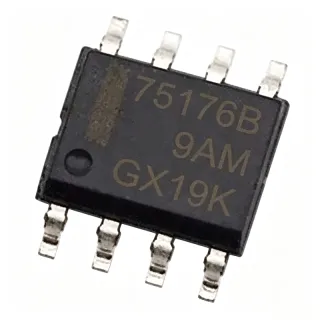
P4SMAJ45 - 45V 400W SMA TVS Diode, Unidirectional | Diotec
MPN: P4SMAJ45 ✓ Active| Qty | Unit Price | Extended |
|---|---|---|
| 1 | $0.58 | $0.58 |
| 10 | $0.52 | $5.20 |
| 100 | $0.42 | $42.00 |
| 500 | $0.35 | $175.00 |
| 1,000 | $0.29 | $290.00 |
| 3,000 | $0.24 | $720.00 |
P4SMAJ45 Overview
A Transient Voltage Suppressor (TVS) is a specialized clamping diode optimized to absorb brief, high-energy overvoltage transients such as those caused by inductive load switching, relay coil kickback, electrostatic discharge (ESD), or induced lightning surges. TVS diodes sit in parallel with the protected load, present a high impedance at normal operating voltage, and avalanche into low impedance once the breakdown threshold is exceeded. As a sub-family of discrete semiconductor protection devices, TVS parts belong to the broader Surge Protectors category within power management and circuit protection. P4SMAJ45 is one of the 400 W P4SMAJ series, distinguished from the lower-energy 400 W SMAJ series only by slightly different test conditions, while sharing the same SMA footprint and pinout.
Key features include 400 W peak pulse power on a 10/1000 µs waveform, unidirectional polarity, glass-passivated junction construction, and compatibility with automated reflow soldering on standard SMA land patterns. Maximum clamping voltage of 80.3 V at 5 A (IPP) and low leakage at the 45 V working voltage keep steady-state losses negligible.
Typical applications include 48 V telecom interface protection, 24/36 V industrial bus transient suppression, DC motor and solenoid snubbing, and protection of signal lines crossing electrically noisy factory environments. The 45 V stand-off rating suits rails whose nominal voltage sits below 45 V but which can experience switching spikes approaching the breakdown region.
A common design pitfall is selecting a TVS whose stand-off voltage is too close to the normal operating rail; this shortens device life. Always derate the working voltage by at least 10 % to ensure the P4SMAJ45 only conducts during real transients.
This page consolidates distributor pricing, same-package drop-in alternatives, and practical PCB layout notes to help engineers qualify P4SMAJ45 quickly into 48 V interface and industrial bus designs.
Drop-in alternatives for P4SMAJ45 — same package, pin-to-pin compatible. Different-package parts requiring PCB rework are excluded.
Quick Comparison Tool — Select alternative parts for side-by-side comparison:
P4SMAJ45_R2_00001
✅ Drop-In📋 Reference alternative (not in catalog)
P4SMAJ45A
✅ Drop-In📋 Reference alternative (not in catalog)
SMAJ45A
✅ Drop-In📋 Reference alternative (not in catalog)
TPSMAJ45A
✅ Drop-In📋 Reference alternative (not in catalog)
P4SMAJ45C
✅ Drop-In📋 Reference alternative (not in catalog)
SMAJ45CA
✅ Drop-In📋 Reference alternative (not in catalog)
P4SMAJ45 Maximum Ratings & Electrical Characteristics
| Manufacturer | Diotec Semiconductor |
| Product Type | Transient Voltage Suppressor (TVS) Diode |
| Series | P4SMAJ |
| Package / Case | DO-214AC (SMA) |
| Mounting Type | Surface Mount |
| Configuration | Single |
| Directionality | Unidirectional |
| Working Stand-off Voltage (VRWM) | 45 V |
| Breakdown Voltage (VBR) Min | 50 V |
| Breakdown Voltage (VBR) Max | 61.5 V |
| Clamping Voltage (VC) at IPP | 80.3 V |
| Peak Pulse Current (IPP) | 5 A |
| Peak Pulse Power (PPP) at 10/1000 µs | 400 W |
| Junction Temperature Range | -55 °C to +150 °C |
| RoHS Status | RoHS Compliant (suffix F) |
P4SMAJ45 Pin Configuration
| Pin 1 | Cathode — Connects to the protected positive rail (cathode bar mark on package body) |
| Pin 2 | Anode — Connects to ground or the negative rail |
Typical Applications
P4SMAJ45 is suitable for 7 applications: 48 V Telecom Interface Protection, 24 V / 36 V Industrial Bus Transient Suppression, DC Motor and Solenoid Snubbing, Automotive 12 V / 24 V Load Dump Protection (Non-Safety), ESD Protection for Outdoor Sensor Lines, Power Supply Output Overvoltage Crowbar, Battery Management Secondary Protection.
48 V Telecom Interface Protection
The P4SMAJ45's 45 V working stand-off and 80.3 V clamping ceiling fit directly across 48 V nominal telecom rails whose transient envelope is defined by ITU-T K.20/K.21 surge profiles. Placing the diode between the 48 V feed and ground provides a low-impedance path once spikes exceed the breakdown threshold, limiting the residual voltage seen by downstream line drivers and DC-DC converters. Its 400 W peak pulse rating on a 10/1000 µs waveform covers most induced lightning transients encountered on outdoor copper lines.
Recommended
24 V / 36 V Industrial Bus Transient Suppression
Factory floor PLCs, motor drives, and sensor networks running on 24 V or 36 V DC bus rails are routinely exposed to switching spikes from relays, contactors, and inverters. The P4SMAJ45's 45 V stand-off leaves sufficient margin above a 36 V bus while still triggering well below the 60 V typical transient rating of downstream DC-DC modules. Its SMA footprint allows drop-in protection on existing bus nodes, and the 5 A peak pulse current handles the inrush of cable-discharge transients without saturating the junction.
Recommended
DC Motor and Solenoid Snubbing
When a DC motor or solenoid coil is de-energized, the collapsing magnetic field generates a back-EMF spike that can exceed the supply voltage by an order of magnitude and destroy nearby MOSFETs or driver ICs. The P4SMAJ45 placed directly across the coil clamps this spike to a safe value before it reaches the switching transistor. Its low leakage at 45 V and fast avalanche response (sub-microsecond) make it well suited for repetitive switching cycles in industrial automation equipment.
Recommended
Automotive 12 V / 24 V Load Dump Protection (Non-Safety)
Although P4SMAJ45 itself is not AEC-Q101 qualified, its 45 V stand-off is useful in non-safety automotive electronics where 24 V truck or 12 V jump-start transients appear on auxiliary loads. For systems where AEC-Q101 is mandatory, engineers select the qualified equivalent. The 400 W class handles typical load-dump decay times and pairs naturally with a PTC fuse or eFuse for coordinated protection.
Recommended
ESD Protection for Outdoor Sensor Lines
Sensor lines running outdoors (weather stations, irrigation controllers, security detectors) accumulate electrostatic charge and are vulnerable to human-body-model ESD events at the connector. The P4SMAJ45 placed at the cable-entry PCB node clamps ESD strikes to below 80.3 V before they propagate into the analog front end. Combined with a series resistor or common-mode choke, it provides a robust first-line defense for 24 V sensor interfaces.
Recommended
Power Supply Output Overvoltage Crowbar
In isolated DC-DC converter outputs, the P4SMAJ45 serves as a low-cost crowbar that avalanches if the output rail ever rises above the 50 V minimum breakdown. Its 400 W rating is sufficient to absorb the converter's stored output capacitance energy during a fault, blowing the upstream fuse or triggering the converter's OVP latch. The SMA footprint requires minimal PCB real estate, making it ideal for compact point-of-load designs.
Recommended
Battery Management Secondary Protection
Multi-cell Li-ion battery packs with strings above 36 V nominal occasionally see transient events during relay interruption or cell imbalance faults. The P4SMAJ45 placed across the pack terminals provides a secondary clamp below the cell OVP threshold of the monitoring IC. Its low steady-state leakage at 45 V is acceptable for most battery-management quiescent budgets, and the SMA footprint fits alongside fuse and balancing hardware on the BMS board.
Recommended
Recommended Products Summary
Engineering reference data for P4SMAJ45 — comparison, design guidance, and compliance information.
Selection Guide
Comparison with Alternatives
| Parameter | This Product | P4SMAJ45_R2_00001 | P4SMAJ45A | SMAJ45A | TPSMAJ45A | P4SMAJ45C |
|---|---|---|---|---|---|---|
| Package | DO-214AC (SMA) | DO-214AC (SMA) - same | DO-214AC (SMA) - same | DO-214AC (SMA) - same | DO-214AC (SMA) - same | DO-214AC (SMA) - same |
| Brand | Diotec Semiconductor | PanJit | Diotec | Littelfuse | Taiwan Semiconductor | PanJit |
| Working Stand-off Voltage (VRWM) | 45 V | 45 V | 45 V | 45 V | 45 V | 45 V |
| Breakdown Voltage Min (VBR) | 50 V | 50 V | 50 V (±5%) | 50 V | 50 V | 50 V |
| Clamping Voltage Max (VC) | 80.3 V | 80.3 V | 80.3 V | 72.7 V (tighter) | 77 V typical | 80.3 V |
| Peak Pulse Power (PPP) 10/1000 µs | 400 W | 400 W | 400 W | 400 W | 400 W | 400 W |
| Directionality | Unidirectional | Unidirectional | Unidirectional | Unidirectional | Unidirectional | Bidirectional |
Key Differentiators
- Tightest clamping ceiling among listed 45 V VRWM TVS in SMA (vs SMAJ45A (Littelfuse))
- Bidirectional option exists in the same family on the same footprint (vs P4SMAJ45C (PanJit))
- AEC-Q101 automotive equivalents available from cross-brand (vs P4SMAJ45_R2_00001 (PanJit) and SMAJ45A (Littelfuse))
Design Notes
Place the P4SMAJ45 as close as physically possible to the connector or terminal where the transient enters the PCB. Keep the trace between the protected rail and the TVS cathode under 5 mm and use a wide ground pour on the anode side to minimize parasitic inductance, which otherwise causes the actual clamping voltage to overshoot the 80.3 V datasheet value during sub-microsecond edges.
Although peak pulse dissipation is rated 400 W for a 10/1000 µs waveform, the average power dissipation under repetitive surges is limited by the thermal resistance of the SMA land pattern. Estimated: with a JEDEC-standard 1 oz copper SMA pad on a 1.6 mm FR-4 board, theta_JA is approximately 150 °C/W; a 1 W average load therefore raises junction temperature by ~150 °C above ambient. For repetitive transients, ensure average power stays below 1 W or add thermal vias under the cathode pad.
Do not select a TVS whose VRWM sits at or above the normal operating rail voltage; this causes constant leakage current and accelerated aging. For a 48 V nominal telecom rail, the 45 V VRWM of P4SMAJ45 leaves only ~6 % margin - acceptable but tight. If the rail tolerance is ±10 % or the system sees sustained over-voltage during fault conditions, derate to a 36 V or 40 V stand-off TVS instead.
Compliance Information
RoHS compliance per the suffix-F designation noted on the Diotec datasheet. AEC-Q100/AEC-Q101 not qualified by Diotec for this industrial/commercial part. For automotive designs, select an AEC-Q101-qualified cross-brand equivalent such as SMAJ45A-Q1.