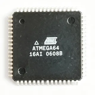
PIC16F747T-I/PT - 8-Bit 20MHz 7KB Flash MCU 44-TQFP | Microchip
MPN: PIC16F747T-I/PT ✓ Active| Qty | Unit Price | Extended |
|---|---|---|
| 1 | $3.21 | $3.21 |
| 10 | $2.92 | $29.20 |
| 100 | $2.61 | $261.00 |
| 500 | $2.34 | $1,170.00 |
| 1,000 | $2.1 | $2,100.00 |
PIC16F747T-I/PT Overview
What is a PIC16 microcontroller? The PIC16F family is a group of 8-bit microcontrollers from Microchip Technology built on a Harvard RISC architecture. The "16" designation positions this family between the baseline PIC10/12/16 families and the high-performance PIC18/dsPIC lines, balancing code density, peripheral integration, and cost. PIC16F parts typically feature nanoWatt power management, multiple timers, USART, MSSP (SPI/I2C), 10-bit ADC, and PWM modules - making them workhorses for embedded control in industrial, consumer, and appliance applications.
Key specifications of the PIC16F747T-I/PT include 36 I/O pins across five ports, a 10-bit ADC with up to 14 channels, two 8-bit timers plus one 16-bit timer, a 10-bit PWM module with enhanced capture/compare, an Enhanced USART supporting RS-485/RS-232, and an MSSP peripheral supporting both SPI and I2C (master/slave). The device operates from 4.0V to 5.5V with nanoWatt sleep currents typically below 100 nA, and it offers in-circuit serial programming (ICSP) via two pins.
The PIC16F747 architecture combines a 14-bit instruction word with 35 single-word instructions, an 8-level hardware stack, and a deterministic interrupt controller. Compared to the older PIC16C5X baseline, the 'F747 adds Flash self-write, peripheral pin select flexibility, and nanoWatt power modes - features inherited from the PIC16F7X7 family lineage shared with the PIC16F737, PIC16F767, and PIC16F777 siblings.
Typical applications include industrial control panels, motor control with PWM, HVAC thermostat and sensor interfaces, RS-485 networked sensor nodes, white-goods and appliance control boards, and general-purpose 5V embedded designs. Its 5V tolerance on digital inputs and 36 available I/Os make it well suited for legacy parallel buses and switch-debounced input matrices.
When designing with the PIC16F747T-I/PT, ensure decoupling capacitors (100 nF plus 10 uF bulk) are placed within 5 mm of the VDD pins and that the MCLR pull-up is no smaller than 10 kohm to avoid false resets. For noise-sensitive analog designs, dedicate one AVdd/AVss pair with its own ferrite-bead filter.
This page synthesizes distributor pricing, drop-in alternatives, and practical design notes beyond the manufacturer datasheet, providing engineers with a single source for sourcing decisions, lifecycle assessment, and qualified cross-brand equivalents.
Drop-in alternatives for PIC16F747T-I/PT — same package, pin-to-pin compatible. Different-package parts requiring PCB rework are excluded.
Variants in this series
Same-series models that are drop-in compatible with PIC16F747T-I/PT (same form factor and footprint) — differing in ADC, Operating Temperature, Package, Timers, Core Architecture.
Quick Comparison Tool — Select alternative parts for side-by-side comparison:
PIC16F747-I/PT
✅ Drop-In✓ In Stock
$4.4 / Unit
View Datasheet →PIC16F777T-I/PT
✅ Drop-In ⚠️ Specs Unverified✓ In Stock
$4.65 / Unit
View Datasheet →PIC16F747T-I/ML
✅ Drop-In ⚠️ Specs Unverified📋 Reference alternative (not in catalog)
PIC16F747-E/ML
✅ Drop-In✓ In Stock
$2.85 / Unit
View Datasheet →PIC16F747T-I/PT Maximum Ratings & Electrical Characteristics
| Core Architecture | PIC16 enhanced mid-range 8-bit RISC |
| Instruction Word | 14-bit |
| Instruction Set Size | 35 instructions |
| Maximum CPU Speed | 20 MHz (200 ns instruction cycle) |
| Program Memory (Flash) | 7 KB (4K x 14) |
| RAM | 368 bytes |
| I/O Pins | 36 |
| Operating Voltage (VDD) | 4.0 V to 5.5 V |
| ADC | 10-bit, up to 14 channels |
| Timers | 2 x 8-bit + 1 x 16-bit |
| PWM Channels | 10-bit PWM (3 CCP/ECCP modules per datasheet family) |
| Communication Peripherals | Enhanced USART, MSSP (SPI / I2C) |
| Operating Temperature | -40C to +85C (Industrial) |
| Package | 44-TQFP (10 x 10 mm) |
| Mounting Type | Surface Mount |
| Packaging Form | Tape and Reel (T suffix) |
| RoHS Status | Compliant |
| Lead-Free | Yes |
| Programming Interface | ICSP (In-Circuit Serial Programming) |
| MSL Level | 3 (168 hours) |
PIC16F747T-I/PT Pin Configuration
| Pin 1 | RA0/AN0 — PORTA bit 0 / analog input channel 0 |
| Pin 2 | RA1/AN1 — PORTA bit 1 / analog input channel 1 |
| Pin 3 | RA2/AN2/VREF- — PORTA bit 2 / analog input channel 2 / ADC negative reference |
| Pin 4 | RA3/AN3/VREF+ — PORTA bit 3 / analog input channel 3 / ADC positive reference |
| Pin 5 | RA4/AN4 — PORTA bit 4 / analog input channel 4 |
| Pin 6 | RA5/AN5/SS — PORTA bit 5 / analog input channel 5 / SPI slave select |
| Pin 7 | RE0/RD — PORTE bit 0 / parallel-port read control |
| Pin 8 | RE1/WR — PORTE bit 1 / parallel-port write control |
| Pin 9 | RE2/CS — PORTE bit 2 / parallel-port chip select |
| Pin 10 | VDD — Positive supply voltage |
| Pin 11 | VSS — Ground reference |
| Pin 12 | OSC1/CLKI — External crystal/clock input |
| Pin 13 | OSC2/CLKO — External crystal/clock output |
| Pin 14 | RC0/T1OSO/T1CKI — PORTC bit 0 / Timer1 oscillator output / Timer1 clock input |
| Pin 15 | RC1/T1OSI/CCP2 — PORTC bit 1 / Timer1 oscillator input / CCP2 module |
| Pin 16 | RC2/CCP1 — PORTC bit 2 / CCP1 module |
| Pin 17 | RC3/SCK/SCL — PORTC bit 3 / MSSP SPI clock / I2C clock |
| Pin 18 | RC4/SDI/SDA — PORTC bit 4 / MSSP SPI data in / I2C data |
| Pin 19 | RC5/SDO — PORTC bit 5 / MSSP SPI data out |
| Pin 20 | RC6/TX/CK — PORTC bit 6 / Enhanced USART TX / clock |
| Pin 21 | RC7/RX/DT — PORTC bit 7 / Enhanced USART RX / data |
| Pin 22 | RD0/PSP0 — PORTD bit 0 / parallel slave port bit 0 |
| Pin 23 | RD1/PSP1 — PORTD bit 1 / parallel slave port bit 1 |
| Pin 24 | RD2/PSP2 — PORTD bit 2 / parallel slave port bit 2 |
| Pin 25 | RD3/PSP3 — PORTD bit 3 / parallel slave port bit 3 |
| Pin 26 | RD4/PSP4 — PORTD bit 4 / parallel slave port bit 4 |
| Pin 27 | RD5/PSP5 — PORTD bit 5 / parallel slave port bit 5 |
| Pin 28 | RD6/PSP6 — PORTD bit 6 / parallel slave port bit 6 |
| Pin 29 | RD7/PSP7 — PORTD bit 7 / parallel slave port bit 7 |
| Pin 30 | VSS — Ground reference |
| Pin 31 | VDD — Positive supply voltage |
| Pin 32 | RB0/INT — PORTB bit 0 / external interrupt |
| Pin 33 | RB1 — PORTB bit 1 |
| Pin 34 | RB2 — PORTB bit 2 |
| Pin 35 | RB3 — PORTB bit 3 |
| Pin 36 | RB4 — PORTB bit 4 |
| Pin 37 | RB5 — PORTB bit 5 |
| Pin 38 | RB6/PGC — PORTB bit 6 / ICSP clock |
| Pin 39 | RB7/PGD — PORTB bit 7 / ICSP data |
| Pin 40 | MCLR/VPP — Master clear reset (active-low) / programming voltage |
| Pin 41 | RA6/OSC2 — PORTA bit 6 / alternate oscillator output |
| Pin 42 | RA7/OSC1 — PORTA bit 7 / alternate oscillator input |
| Pin 43 | AVSS — Analog ground reference |
| Pin 44 | AVDD — Analog positive supply voltage |
Typical Applications
PIC16F747T-I/PT is suitable for 7 applications: Industrial Control Panels, HVAC Thermostat and Sensor Interface, Brushed-DC and Small BLDC Motor Control, White-Goods and Appliance Control Boards, RS-485 Networked Sensor Nodes, General-Purpose 5V Embedded Boards, Automotive Aftermarket Accessories.
Industrial Control Panels
The PIC16F747T-I/PT is well suited to industrial control-panel designs because its 36 I/O pins drive multiplexed keypads, segmented LED indicators, and relay banks directly without external buffers, while the 10-bit ADC with up to 14 channels reads 4-20 mA loop transmitters through a burden resistor. The 5V rail tolerance and -40C to +85C industrial grade per the Microchip datasheet let it sit inside sealed enclosures, and the Enhanced USART with hardware address detection supports RS-485 multi-drop networks on factory floors. Compared with newer Cortex-M0 parts, the F747 trades compute throughput for BOM simplicity - one chip replaces external port expanders, easing BOM and qualification.
Recommended
HVAC Thermostat and Sensor Interface
In HVAC thermostats and environmental sensor interfaces the PIC16F747T-I/PT delivers the right mix of precision analog and digital I/O. Its 10-bit ADC scans NTC thermistors for ambient and discharge-air temperature, while PWM outputs modulate triac drivers for fan speed control. nanoWatt sleep currents below 100 nA, per the PIC16F737/767/747/777 datasheet, allow multi-year battery life on wireless thermostat variants. The 44-TQFP footprint exposes enough I/O to also drive a 128-segment LCD via the MSSP peripheral and an external LCD driver, avoiding a costly display controller.
Recommended
Brushed-DC and Small BLDC Motor Control
For brushed-DC and small brushless-DC motor drives the PIC16F747T-I/PT's ECCP modules generate center-aligned 10-bit PWM at 20 kHz without software overhead, supporting quiet, efficient motor commutation. The 16-bit Timer1 times Hall-sensor edges for RPM feedback, while the Enhanced USART links to a host controller for closed-loop commands. With 25 mA sink/source capability per pin, the MCU can pull MOSFET half-bridge gate drivers like the TC4427 directly. The 7 KB Flash accommodates lookup tables for sensorless BEMF startup routines in entry-level BLDC tools and appliances.
Recommended
White-Goods and Appliance Control Boards
Washing machines, dishwashers, and induction-cooktop controllers benefit from the PIC16F747T-I/PT's 5V tolerance, 36 I/O count, and robust peripheral set per the Microchip datasheet. The MCU multiplexes the seven-segment display, reads water-level and temperature sensors through the 10-bit ADC, and drives triac outputs via zero-cross interrupts on the 16-bit timer. Its 35-instruction RISC core simplifies IEC 60730 class-B software self-test certification, a frequent requirement for white-goods. Industrial -40C to +85C operation tolerates the heat inside an appliance cabinet.
Recommended
RS-485 Networked Sensor Nodes
The PIC16F747T-I/PT is an excellent host for distributed sensor nodes on an RS-485 bus because its Enhanced USART supports 9-bit address-mode framing for multi-drop polling without software bit-banging. The 14-channel 10-bit ADC aggregates thermistor, pressure, and flow-rate signals in a single MCU. With 368 bytes of RAM, the F747 buffers packets while the MSSP I2C master reads external EEPROM calibration tables. Industrial-grade silicon and a 44-TQFP that exposes RGBA/EMCU pins make PCB routing of the bus transceiver straightforward.
Recommended
General-Purpose 5V Embedded Boards
Designers use the PIC16F747T-I/PT as a universal 5V MCU on general-purpose boards - educational kits, retro-computing peripherals, and hobbyist controllers. Its 35-instruction PIC16F assembly language and ICD/ICSP debug header support accelerate learning, while the 44-TQFP exposes all five ports for breadboard-friendly breakout boards. Per the Microchip datasheet, the device powers up cleanly from 4.5V USB rails and tolerates the noise of switching regulators on the same PCB. The 7 KB Flash is generous for small RTOS kernels and custom bootloaders written in C18 or XC8.
Recommended
Automotive Aftermarket Accessories
Although the PIC16F747T-I/PT is industrial-grade rather than AEC-Q100 qualified, it fits automotive aftermarket accessories such as gauge clusters, alarm modules, and lighting controllers that operate inside the cabin rather than under the hood. The 36 I/O drive RGB LED strips and seven-segment readouts, while the 10-bit ADC monitors battery voltage through a divider. The 44-TQFP is large enough to hand-rework in prototype quantities, helpful for low-volume aftermarket production. For under-hood modules engineers should migrate to the AEC-Q100 PIC16F15325 family.
Recommended
Recommended Products Summary
Engineering reference data for PIC16F747T-I/PT — comparison, design guidance, and compliance information.
Selection Guide
Comparison with Alternatives
| Parameter | This Product | PIC16F747-I/PT | PIC16F777T-I/PT | PIC16F747T-I/ML | PIC16F747-E/ML |
|---|---|---|---|---|---|
| Package | 44-TQFP (10x10 mm) | 44-TQFP (10x10 mm) - same | 44-TQFP (10x10 mm) - same | 44-QFN (ML) - same pin count | 44-QFN (ML) - same pin count |
| Brand | Microchip Technology | Microchip Technology - same | Microchip Technology - same | Microchip Technology - same | Microchip Technology - same |
| Flash Program Memory | 7 KB (4K x 14) | 7 KB | 14 KB | 7 KB | 7 KB |
| RAM | 368 bytes | 368 bytes | 368 bytes | 368 bytes | 368 bytes |
| Maximum CPU Speed | 20 MHz / 5 MIPS | 20 MHz / 5 MIPS | 20 MHz / 5 MIPS | 20 MHz / 5 MIPS | 20 MHz / 5 MIPS |
| I/O Pins | 36 | 36 | 36 | 36 | 36 |
| Operating Voltage | 4.0 V to 5.5 V | 4.0 V to 5.5 V | 4.0 V to 5.5 V | 4.0 V to 5.5 V | 4.0 V to 5.5 V |
| Operating Temperature | -40C to +85C (Industrial) | -40C to +85C (Industrial) | -40C to +85C (Industrial) | -40C to +85C (Industrial) | -40C to +125C (Extended) |
| Packaging Form | Tape and Reel | Tube | Tape and Reel | Tape and Reel | Tube / Tape and Reel |
Key Differentiators
- 5V industrial-grade tolerance in a 44-TQFP package (vs PIC16F737-I/SP)
- Tape and Reel packaging for SMT production (vs PIC16F747-I/PT)
- Extended upgrade path to PIC16F777T-I/PT with no PCB rework (vs PIC16F777T-I/PT)
Design Notes
Place a 100 nF ceramic decoupling capacitor within 5 mm of each VDD pin (pins 10 and 31) and a single 10 uF bulk tantalum or ceramic on the supply rail. Add a dedicated ferrite-bead plus 10 uF/100 nF pair on the AVDD/AVSS pins (43 and 44) for ADC accuracy per the Microchip datasheet. Estimate: with all peripherals enabled, the F747 draws about 8 mA at 5 V and 20 MHz, so the bulk capacitor must hold VDD above 4.5 V during a 10 ms inrush on inductive loads.
Route the ICSP signals (RB6/PGC and RB7/PGD) on the same layer with no vias, keeping them under 50 mm trace length. Leave a 6-pin header footprint for the PIC-KIT3 connector even on production boards - field firmware updates save RMAs. According to the PIC16F737/767/747/777 datasheet, the MCLR pin (40) requires a 10 kohm pull-up to VDD and a 100 nF to ground for in-circuit debug; do not omit either or debug will fail intermittently.
Estimated: at full 20 MHz operation with all 36 I/Os toggling at 50 pF load, the F747 dissipates around 0.4 W. The 44-TQFP (10x10) package has theta_JA of approximately 50 C/W on a 4-layer JEDEC test board, yielding a junction temperature rise of 20 C above ambient. For -40C to +85C industrial designs this leaves adequate margin, but in enclosed cabinets consider a copper-pour heat spreader under the exposed die pad equivalent of the QFN/ML variant.
Do not leave unused I/O pins floating - the datasheet requires them tied to VDD or VSS to prevent input-toggle current that can add 1-2 mA of quiescent draw. When using the ADC, configure the TRIS registers for analog pins even on unused channels, or the digital input buffer will inject noise into the conversion. Finally, the parallel slave port (PORTD + PORTE) must be unlocked via the PSPMODE bit before use; failing to do so leaves RD and RE stuck in digital I/O mode.
Compliance Information
RoHS and lead-free compliant per Microchip product page. Industrial-grade (-40C to +85C), not AEC-Q100 qualified. For automotive under-hood designs use the AEC-Q100 PIC16F15325 family instead.