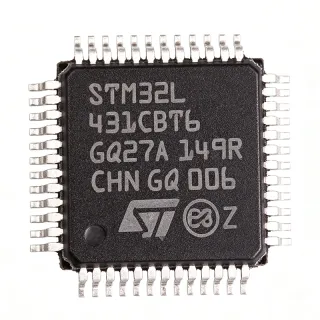
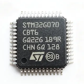
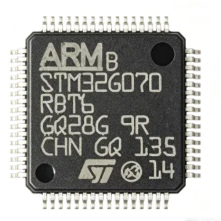
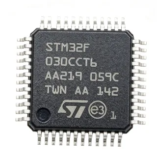
LPC4367JET100E - 204MHz Dual-Core Cortex-M4/M0 MCU, 1MB Flash | NXP
N.º da peça: LPC4367JET100E ✓ AtivoLPC4367JET100E Visão geral
A microcontroller is a programmable system-on-chip that integrates a CPU core, memory and peripherals onto one die. The LPC43xx family belongs to the embedded microcontroller segment of integrated circuits, sitting between simple 8/16-bit controllers and higher-end application processors. Its Arm Cortex-M4 core carries the main application workload while an Arm Cortex-M0 subsystem handles peripheral management, and the M0 coprocessor is explicitly designed as a replacement for existing 8/16-bit microcontrollers with up to 204 MHz performance and a reduced code size.
Key features of the LPC4367JET100E include dual-core operation at 204 MHz, 1 MB of flash for firmware and data, 154 kB of SRAM for working buffers, and 16 kB of on-chip EEPROM for parameter storage. The Cortex-M0 hardware multiply is implemented as a 32-cycle iterative multiplier, which keeps coprocessor execution deterministic. Two independent high-speed USB interfaces allow simultaneous host/device or dual-device connectivity, and the integrated Ethernet MAC supports networked industrial and communications equipment.
Internally, the device combines an Arm Cortex-M4 processor with an Arm Cortex-M0 subsystem for managing peripherals, plus a separate Cortex-M0 coprocessor. Memories and peripherals sit behind an efficient bus matrix, and the LCD controller and EMC peripherals support display-driven human-interface designs. The LPC436x family targets embedded applications that need connectivity plus real-time control.
Typical applications include industrial Ethernet gateways, USB-to-Ethernet bridges, PLC and data-acquisition controllers, human-machine interface panels with integrated LCD, and connected sensor or building-automation nodes. Because the MCU integrates USB, Ethernet and LCD control in one package, many designs replace a multi-chip processor-plus-interface solution.
When designing with the LPC4367JET100E, plan power and decoupling carefully around the 204 MHz core, keep high-speed USB and Ethernet traces short and reference-controlled, and leave the BGA escape routing dense enough for clean layer changes. A 100-ball TFBGA also demands a careful ball-map review and adequate thermal vias under the die.
This page assembles the NXP product information, distributor availability listings and the LPC436x family datasheet into one engineering reference, adding drop-in alternatives, parameter-by-parameter comparison and practical design notes that go beyond the manufacturer overview.
Alternativas drop-in para LPC4367JET100E — mesmo encapsulamento, compatível pino a pino. Peças de encapsulamento diferente que exigem retrabalho na PCB são excluídas.
Variantes desta série
Modelos da mesma série compatíveis como drop-in com LPC4367JET100E (mesmo formato e footprint) — diferindo em On-Chip SRAM, Package, Ethernet.
LPC4367JET100
✅ Drop-In📋 Alternativa de referência (fora do catálogo)
LPC4337JET100E
✅ Drop-InConsulte o preço
Ver ficha técnica →LPC4357JET100
✅ Drop-In ⚠️ Especificações não verificadas📋 Alternativa de referência (fora do catálogo)
LPC4357FBD100
✅ Drop-In ⚠️ Especificações não verificadas📋 Alternativa de referência (fora do catálogo)
LPC4367FBD100
✅ Drop-In ⚠️ Especificações não verificadas📋 Alternativa de referência (fora do catálogo)
LPC4367JET100E Classificações máximas e características elétricas
| Core Processor | Arm Cortex-M4 with Arm Cortex-M0 subsystem and Cortex-M0 coprocessor |
| Architecture | 32-bit ARM, Harvard-style instruction set |
| Maximum CPU Frequency | 204 MHz |
| Number of Cores | 2 (Cortex-M4 + Cortex-M0) |
| Flash Memory Size | 1 MB (1M x 8) |
| On-Chip SRAM | 154 kB |
| On-Chip EEPROM | 16 kB |
| USB Interfaces | 2 x high-speed USB |
| Ethernet | Integrated Ethernet MAC |
| LCD Controller | Yes |
| EMC Peripherals | Yes |
| Cortex-M0 Hardware Multiply | 32-cycle iterative multiplier |
| Series | LPC43xx |
| Encapsulamento | TFBGA-100 (9x9 mm) |
| Tipo de montagem | Surface Mount |
Guia de Configuração de Pinos do LPC4367JET100E tfbga-100 (9x9 mm)
Configuração de pinos para LPC4367JET100E (pacote tfbga-100 (9x9 mm)). Este CI digital inclui GPIO, interfaces de comunicação (UART, SPI, I2C) e pinos de alimentação. Consulte o datasheet do fabricante para funções alternativas dos pinos e opções de configuração. Essencial para projeto de sistemas embarcados e layout de PCB.
Nenhum dado detalhado de pinagem disponível para LPC4367JET100E.
Consulte a ficha técnica para a configuração completa dos pinos.
Aplicações típicas
LPC4367JET100E é adequado para 6 aplicaçãos: Industrial Ethernet Gateway and Protocol Converter, USB-to-Ethernet and USB-to-Serial Bridge Products, Human-Machine Interface Panels with LCD Display, PLC and Data-Acquisition Controller, Connected Sensor and Building Automation Node, Medical and Laboratory Instrument Control Subsystem.
Industrial Ethernet Gateway and Protocol Converter
The LPC4367JET100E suits industrial gateways because it pairs an integrated Ethernet MAC with two high-speed USB ports and a 204 MHz dual-core Cortex-M4/M0 engine in a single 100-ball TFBGA (9x9 mm) package. The Cortex-M4 runs the protocol stack and application logic while the Cortex-M0 subsystem handles peripheral servicing, and 154 kB of SRAM plus 1 MB of flash gives comfortable room for buffering and firmware. Keeping Ethernet, USB and control logic on one die removes the processor-plus-interface-chip arrangement and shrinks the enclosure. Place Ethernet magnetics and a 25 MHz or 50 MHz oscillator close to the device and route the differential pairs over a continuous ground plane to keep return-path discontinuities out of the data channel.
Recomendado
USB-to-Ethernet and USB-to-Serial Bridge Products
With two independent high-speed USB interfaces and 1 MB of flash, the LPC4367JET100E can host a complete dual-port USB-to-Ethernet bridge, with one port facing the host PC and the other facing an industrial peripheral, or drive USB-to-serial and USB-to-serial protocol converters. The 204 MHz Cortex-M4 leaves headroom for USB stack overhead, and the M0 subsystem can service the USB host logic independently. 154 kB of SRAM absorbs descriptor tables and packet buffers, so external memory is rarely required. Keep the USB differential pairs routed as a matched length pair over a solid plane, provide the specified series damping, and route the 48 MHz and 32 MHz crystals away from the Ethernet magnetics.
Recomendado
Human-Machine Interface Panels with LCD Display
The LPC4367JET100E integrates an LCD controller alongside its dual-core processing, which shortens the design path for touch and button-driven operator panels used in machinery, test equipment and building controls. The LCD engine can drive the panel directly while the Cortex-M4 handles graphics and the application layer, and the Cortex-M0 subsystem manages button scanning and periodic housekeeping tasks. The 1 MB flash accommodates display fonts and bitmap assets, and 154 kB of SRAM supports page or frame buffering. Because the part is a 100-ball TFBGA (9x9 mm), the LCD ribbon connector and touch controller interface should be routed on the same layer as the escape fan-out where possible, keeping switching-node and Ethernet regions physically separated from the display signals.
Recomendado
PLC and Data-Acquisition Controller
The LPC4367JET100E is a natural fit for compact PLC and data-acquisition controllers that must run a real-time control loop while also serving Ethernet or USB connectivity. The 204 MHz Cortex-M4 core provides the deterministic execution needed for tight scan cycles, and the Cortex-M0 coprocessor, described by NXP as a replacement for existing 8/16-bit microcontrollers, can offload peripheral servicing or legacy protocol handling without disturbing the main loop. 16 kB of EEPROM holds calibration constants and node configuration across power cycles, while 154 kB of SRAM supports sample buffers. Use a dedicated supervisor for reset and brown-out handling, keep the analog front end on a separate protected section of the board, and confirm the ADC and timer pin multiplexing against the NXP ball map for the exact part number.
Recomendado
Connected Sensor and Building Automation Node
Building-automation and IoT sensor nodes benefit from the combination of a 204 MHz dual-core MCU, 1 MB flash and Ethernet plus dual USB connectivity in a 9 x 9 mm TFBGA footprint, which allows the node to run local edge processing, protocol conversion and secure firmware updates from a single device. The Cortex-M0 subsystem can maintain the sensor sampling cadence while the Cortex-M4 handles networking and diagnostics, and the integrated LCD and EMC peripherals simplify local status indication and motorised-valve or relay driving. 154 kB of SRAM is enough for time-series buffering before uplink. Keep the Ethernet magnetics at the board edge, maintain a solid ground plane under the MCU, and provide a thermal-via field beneath the die to handle sustained operation at the 204 MHz clock.
Recomendado
Medical and Laboratory Instrument Control Subsystem
Laboratory and diagnostic instruments need deterministic control with a high-performance host interface, and the LPC4367JET100E provides both through its 204 MHz dual-core Cortex-M4/M0 architecture, 1 MB of flash and integrated USB and Ethernet. The Cortex-M4 can execute the instrument sequencer and UI logic while the M0 subsystem handles interrupt-driven housekeeping, and the 16 kB of EEPROM stores calibration and audit data locally. With USB on board, the instrument connects directly to a host PC without an external bridge, and Ethernet supports networked laboratory management. For safety-conscious designs, isolate the analog front end from the digital section, keep the LCD and Ethernet zones apart on the board, and review the NXP datasheet for the exact ordering code and temperature grade required by the end standard.
Recomendado
Resumo dos produtos recomendados
Dados de referência de engenharia para LPC4367JET100E — comparação, orientação de projeto e informações de conformidade.
Guia de seleção
Select the LPC4357JET100 when you need the same package and clock rate but will not use the LCD controller or EMC outputs; select the LPC4357FBD100 or LPC4367FBD100 only when you intentionally want to boot from external serial flash instead of the 1 MB on-chip flash; and consider the LPC4337JET100 when a lower-flash member of the same footprint family meets the firmware budget.
All listed options share the TFBGA-100 (9x9 mm) footprint, so a PCB can be reused across the family. Because no cross-manufacturer part with the same ball map and peripheral mix was identified, treat cross-brand substitution as a redesign rather than a drop-in swap.
Comparação com alternativas
| Parâmetro | Este produto | LPC4367JET100 | LPC4337JET100 | LPC4357JET100 | LPC4357FBD100 | LPC4367FBD100 |
|---|---|---|---|---|---|---|
| Brand | NXP Semiconductors | NXP Semiconductors | NXP Semiconductors | NXP Semiconductors | NXP Semiconductors | NXP Semiconductors |
| Package | TFBGA-100 (9x9 mm) | TFBGA-100 (9x9 mm) - same | TFBGA-100 (9x9 mm) - same | TFBGA-100 (9x9 mm) - same | TFBGA-100 (9x9 mm) - same | TFBGA-100 (9x9 mm) - same |
| Core | Arm Cortex-M4 + Cortex-M0 subsystem and coprocessor | Arm Cortex-M4 + Cortex-M0 subsystem and coprocessor | Arm Cortex-M4 + Cortex-M0 subsystem and coprocessor | Arm Cortex-M4 + Cortex-M0 subsystem and coprocessor | Arm Cortex-M4 + Cortex-M0 subsystem and coprocessor | Arm Cortex-M4 + Cortex-M0 subsystem and coprocessor |
| Maximum CPU Frequency | 204 MHz | 204 MHz | 204 MHz | 204 MHz | 204 MHz | 204 MHz |
Principais diferenciais
- Full LPC436x peripheral set in the same footprint (vs LPC4357JET100)
- On-chip flash and EEPROM sizing (vs LPC4367FBD100)
- Maximum flash headroom for firmware growth (vs LPC4337JET100)
- Dual independent high-speed USB and Ethernet in one die (vs LPC4357FBD100)
- 204 MHz dual-core throughput with a dedicated coprocessor path (vs LPC4367JET100)
Notas de projeto
The LPC4367JET100E is a 100-ball 9 x 9 mm TFBGA, so layout quality dominates the design. Plan a multilayer stack with a solid uninterrupted ground plane directly beneath the device, route all escape fan-out on the first signal layer with symmetrical via stitching, and use via-in-pad or a via field under the die for both escape and thermal purposes. Place the 32 MHz main oscillator and the 32.768 kHz RTC crystal on the same side of the board as the MCU and close to their assigned balls, with no high-speed or switching node traces routed between the crystal pads and their load capacitors.
Both high-speed USB ports and the Ethernet MAC are on this device, so treat the two USB differential pairs and the Ethernet differential pair as controlled-impedance nets. Match intra-pair length within the tolerance given in the NXP hardware design guidance, provide the specified AC series damping on each USB line, and route Ethernet pairs over continuous plane with no split or void underneath. Keep the Ethernet magnetics at the board edge, place the PHY interface section of the board away from the LCD and EMC driver outputs, and keep switching regulators and inductors physically separated from the USB and Ethernet pairs.
Estimated: at a 3.3 V core rail and 204 MHz operation, the LPC4367JET100E can draw on the order of 100 mA during sustained compute plus additional current for USB, Ethernet and LCD activity. With a 1.8 V core rail the same current at a lower voltage reduces dissipation proportionally. Decouple each supply ball group with a 100 nF ceramic directly at the pin and back it up with bulk capacitance placed close to the device, and verify the DC/DC converter loop bandwidth is set so switching ripple on the core rail stays well inside the tolerance listed in the NXP datasheet power-supply requirements.
Two traps recur in LPC436x designs. First, the family shares much of the TFBGA-100 ball map but does not bond out identical peripherals on every variant, so always work from the ball map and pin-description table for the exact orderable code rather than from a generic LPC43xx drawing. Second, the Cortex-M0 coprocessor in this family uses a 32-cycle iterative hardware multiplier, so code that performs heavy multiplies on the coprocessor runs far slower than on the Cortex-M4; keep compute-heavy work on the M4 and use the coprocessor for peripheral or legacy-protocol tasks only.
Estimated: with a 100-ball TFBGA on a four-layer board, the junction-to-ambient thermal path is dominated by the via field and the plane area beneath the die. Populate a dense thermal-via array directly under the die, keep the top-layer copper pour unbroken around the device, and provide a continuous ground plane on the layer immediately below the ball field. If the product runs the core continuously at 204 MHz in an enclosed enclosure, verify the junction temperature margin against the datasheet maximum using the actual via count and copper area of your layout rather than a generic estimate.
Informações de conformidade
Compliance statements for RoHS, REACH, AEC-Q100 and halogen-free status were not present in the manufacturer or distributor listings available for this part; confirm the current material and process declarations on the NXP product page before committing to a regulated program.