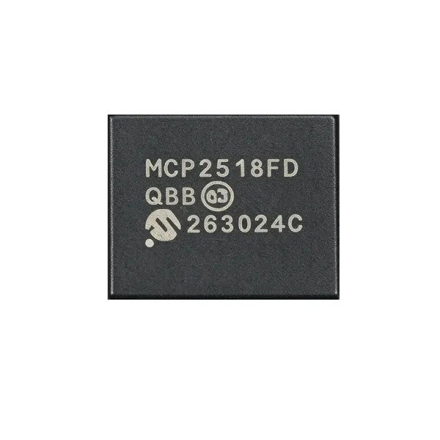
MCP2518FDT-E/QBB - CAN FD Controller, SPI, 14-VDFN | Microchip
N.º da peça: MCP2518FDT-E/QBB ✓ Ativo| Qtd. | Preço unitário | Total |
|---|---|---|
| 1 | $2.45 | $2,45 |
| 10 | $2.18 | $21,80 |
| 100 | $1.89 | $189,00 |
| 500 | $1.65 | $825,00 |
| 1.000 | $1.42 | $1.420,00 |
MCP2518FDT-E/QBB Visão geral
A CAN FD Controller is a peripheral IC that handles the CAN/CAN FD protocol layer independent of the host microcontroller, exposing the bus as a register-mapped SPI slave. In the broader hierarchy, it sits above the physical-layer transceiver (such as the MCP2562FD) and below the application MCU; together these three blocks form a complete ISO 11898-1:2015 CAN node. Using an external controller lets designers add CAN FD to MCUs lacking an integrated CAN module, or offload protocol processing from low-power microcontrollers.
Key features of the MCP2518FDT-E/QBB include up to 1 Mbit/s nominal CAN FD bit rate, 8 Mbit/s SPI clock support, low-power mode drawing approximately 10 µA typical, time-stamping via 32-bit TMR, and a wide operating voltage range of 2.7 V to 5.5 V. The VDFN-14 package occupies only 13.5 mm^2 of board area, making it the smallest CAN FD controller in Microchip's portfolio and ideal for space-constrained ECUs and sensor nodes.
Architecturally, the MCP2518FD uses a dedicated CAN FD protocol engine plus RAM buffers, freeing the host MCU from bit-stuffing, arbitration, and CRC calculation. The SPI interface supports mode 0 and mode 3, with standard read/write commands plus a 16-bit CRC option on critical registers for EMI robustness. Combined with the external MCP2562FD high-speed transceiver, the resulting node is ISO 11898-1:2015 and ISO 11898-2:2016 compliant.
Typical applications include automotive body and chassis networks, industrial CAN nodes (sensor hubs, motor drives), EV battery management (BMS) daisy chains, agricultural and off-highway vehicle telemetry, and any MCU-based system retrofitting CAN FD. The grade-1 (-40C to +125C) qualification makes it suitable for under-hood and chassis-mounted ECUs.
When designing with this device, ensure the VDFN-14 exposed pad is soldered to a sufficiently large ground copper pour for thermal dissipation. A 100 nF decoupling capacitor must be placed within 5 mm of the VDD pin. The oscillator start-up time depends on the crystal load capacitance; consult the Microchip datasheet for matching network values.
This page synthesizes distributor stock levels, parametric drop-in alternatives (including same-package Microchip variants), and PCB-layout guidance that is not consolidated on any single manufacturer or distributor product page.
Alternativas drop-in para MCP2518FDT-E/QBB — mesmo encapsulamento, compatível pino a pino. Peças de encapsulamento diferente que exigem retrabalho na PCB são excluídas.
Ferramenta de comparação rápida — selecione peças alternativas para comparação lado a lado:
MCP2518FDT-H/QBB
📋 Alternativa de referência (fora do catálogo)
MCP2518FDT-E/QBBVAO
📋 Alternativa de referência (fora do catálogo)
MCP2518FDT-E/SL
📋 Alternativa de referência (fora do catálogo)
MCP2518FDT-E/QBB Especificações
| Product Type | CAN FD Controller |
| Protocol Supported | Classical CAN 2.0B and CAN FD (ISO 11898-1:2015) |
| Host Interface | SPI (up to 8 MHz, Mode 0 / Mode 3) |
| Operating Voltage Range (VDD) | 2.7 V to 5.5 V |
| CAN FD Maximum Bit Rate | 1 Mbit/s nominal (data phase up to 8 Mbit/s with external transceiver) |
| SPI Maximum Clock | 8 MHz |
| On-chip RAM (ECC-protected) | 2 KB |
| Corrente no modo de baixa potência | 10 µA typical |
| Operating Temperature Range (Grade 1) | -40C to +125C |
| Interrupt Outputs | 2 (maskable, configurable) |
| Time-Stamp Resolution | 32-bit TMR |
| Encapsulamento | 14-VDFN (4.5 mm x 3 mm) with wettable flanks |
| Tipo de montagem | Surface Mount |
| Status RoHS | Compliant |
| AEC-Q100 Grade | Grade 1 (Automotive qualified per description) |
Configuração de pinos do MCP2518FDT-E/QBB
| Pino 1 | VDD — Power supply input, 2.7 V to 5.5 V |
| Pino 2 | VBAT — Battery backup for low-power RAM (optional) |
| Pino 3 | OSC1 — Crystal oscillator input or external clock input |
| Pino 4 | OSC2 — Crystal oscillator output |
| Pino 5 | GND — Ground reference |
| Pino 6 | TXCAN — CAN transmit output to external transceiver |
| Pino 7 | RXCAN — CAN receive input from external transceiver |
| Pino 8 | nINT0 — Interrupt output 0 (active-low, open-drain) |
| Pino 9 | nINT1 — Interrupt output 1 (active-low, open-drain) |
| Pino 10 | nCS — SPI chip-select input (active-low) |
| Pino 11 | SCK — SPI clock input |
| Pino 12 | SI — SPI slave data input (MOSI) |
| Pino 13 | SO — SPI slave data output (MISO) |
| Pino 14 | nRESET — Device reset input (active-low) |
Aplicações típicas
MCP2518FDT-E/QBB é adequado para 6 aplicaçãos: Automotive Body and Chassis CAN Bus Node, EV Battery Management System Daisy Chain, Industrial Sensor Hub / Motor Drive Node, Agricultural and Off-Highway Vehicle Telemetry, Building Automation and HVAC CANopen Node, Medical Device Monitoring and Diagnostic Interface.
Automotive Body and Chassis CAN Bus Node
The MCP2518FDT-E/QBB is ideally suited for automotive body and chassis CAN nodes that need to retrofit CAN FD onto an existing MCU without an integrated CAN FD peripheral. Its 14-VDFN (4.5x3) package occupies only 13.5 mm^2, leaving room for the MCU, an MCP2562FD transceiver, and supporting passives in compact door-module or seat-controller layouts. The Grade 1 automotive temperature rating (-40C to +125C), ECC-protected 2 KB RAM, and 2.7-5.5 V supply range directly support 12 V automotive battery rails with load-dump protection upstream. The 8 MHz SPI interface keeps firmware port simple on small MCUs like the PIC18 or SAM C20, while low-power 10 µA sleep current lets the node meet dark-current budgets. Use it on CAN FD body networks, lighting controllers, and HVAC modules.
Recomendado
EV Battery Management System Daisy Chain
In an EV battery management system (BMS), the MCP2518FDT-E/QBB adds CAN FD to the slave-side MCU monitoring each cell module, allowing high-speed daisy-chain telemetry back to the master BMS controller. CAN FD's larger 64-byte payload transports per-module voltage, temperature, and balancing state in fewer frames than Classical CAN, reducing bus contention across 12-16 module strings. The controller's 32-bit time-stamp register enables deterministic time synchronization for coulomb counting and isolation-voltage fault logging. Pair the controller with the MCP2562FD transceiver and an isolated CAN coupler such as the ADM3054 for high-voltage side communications. The small 14-VDFN footprint fits the tight geometry of in-pack cell-tap boards.
Recomendado
Industrial Sensor Hub / Motor Drive Node
The MCP2518FDT-E/QBB fits industrial CANopen and DeviceNet sensor hubs where a small PLC or ARM Cortex-M0 MCU needs CAN FD but lacks an integrated CAN FD peripheral. Its SPI host interface at 8 MHz supports fast polled update rates from the hub processor, while the 2 KB RAM holds enough TX/RX buffers for high-traffic encoder, temperature, and vibration streams. The Grade 1 -40C to +125C rating covers factory-floor ambient and motor-housing heat soak. Pair the MCP2518FDT with the MCP2562FD transceiver, isolated DC-DC, and ADM3053 signal coupler for IEC 61800-compliant drive nodes. It is also a strong choice for adding CAN FD to existing PLC backplanes without redesigning the host CPU module.
Recomendado
Agricultural and Off-Highway Vehicle Telemetry
For tractors, harvesters, and other off-highway equipment, the MCP2518FDT-E/QBB offers a compact CAN FD bridge to an operator-display or telematics modem that historically only supported SPI. CAN FD allows high-resolution engine, hydraulic, and implement telemetry at the SAE J1939-21/22 enhanced bit-rate, while the controller's Grade 1 temperature rating handles under-cab and engine-bay environments. The exposed thermal pad of the 14-VDFN package couples to a ground pour for additional thermal margin in enclosed enclosures. Combine with the MCP2562FD and a sealed DEUTSCH or M12 CAN connector for ruggedized field installations.
Recomendado
Building Automation and HVAC CANopen Node
The MCP2518FDT-E/QBB enables small CANopen stacks on HVAC controllers and building-automation nodes that use low-cost MCUs without integrated CAN FD. The 10 µA low-power mode supports Energy Star dark-current budgets on thermostats and air-handler boards. The 2.7-5.5 V supply works directly from 3.3 V or 5 V rails already present on the controller, simplifying BOM. With its 14-VDFN (4.5x3) footprint the controller fits alongside a Bluetooth or Wi-Fi module on the same board. Use it with the MCP2562FD transceiver for a complete CANopen CiA-301 compliant node.
Recomendado
Medical Device Monitoring and Diagnostic Interface
The MCP2518FDT-E/QBB serves medical monitoring devices (infusion pumps, ventilators, anesthesia workstations) that require deterministic, real-time intra-device communications between sensor boards and the main controller. CAN FD's higher bandwidth supports streaming waveforms and alarm logs that Classical CAN cannot, while the 2 KB ECC-protected RAM protects against soft-bit errors in long-running equipment. The Grade 1 automotive temperature range is overkill but ensures reliability. Pair with the MCP2562FD transceiver and IEC 60601-1 isolated power/signal couplers for patient-side isolation. The small 14-VDFN package fits on sensor-PCB mezzanines in compact patient monitors.
Recomendado
Resumo dos produtos recomendados
Dados de referência de engenharia para MCP2518FDT-E/QBB — comparação, orientação de projeto e informações de conformidade.
Guia de seleção
Comparação com alternativas
| Parâmetro | Este produto | MCP2518FDT-H/QBB | MCP2518FDT-E/QBBVAO | MCP2518FDT-E/SL |
|---|---|---|---|---|
| Package | 14-VDFN (4.5x3) | 14-VDFN (4.5x3) - same | 14-VDFN (4.5x3) - same | 14-VDFN (4.5x3) - same |
| Brand | Microchip Technology | Microchip Technology | Microchip Technology | Microchip Technology |
| Operating Temperature Range | -40C to +125C (Grade 1) | -40C to +150C (Grade 0) | -40C to +125C (Grade 1) | -40C to +125C (Grade 1) |
| Automotive Screening | Standard Grade 1 | Standard | VAO (Very Automotive Only) tighter screening | Standard |
| Host Interface | SPI up to 8 MHz | SPI up to 8 MHz - same | SPI up to 8 MHz - same | SPI up to 8 MHz - same |
| On-chip RAM (ECC) | 2 KB | 2 KB - same | 2 KB - same | 2 KB - same |
| Operating Voltage | 2.7 V to 5.5 V | 2.7 V to 5.5 V - same | 2.7 V to 5.5 V - same | 2.7 V to 5.5 V - same |
| Lead Finish | Matte-Tin (Pb-free) | Matte-Tin (Pb-free) | Matte-Tin (Pb-free) | Matte-Tin (Pb-free) |
Principais diferenciais
- Smallest external CAN FD controller in Microchip's portfolio (vs MCP2517FD (SOIC-8))
- Grade 0 temperature option for under-hood placement (vs MCP2518FDT-E/QBB)
- VAO screening tier for high-reliability automotive (vs MCP2518FDT-E/QBB)
Notas de projeto
The MCP2518FDT-E/QBB exposed pad must be soldered to a continuous ground copper pour at least 2 cm^2 in area to meet the 31 C/W thermal resistance spec. Place a 100 nF X7R decoupling capacitor within 5 mm of the VDD pin and a 10 µF bulk capacitor on the same rail. Keep the SCK, SI, SO, and nCS traces matched within 2 mm and isolated from the TXCAN/RXCAN pair by at least 3 mm of ground pour to avoid coupling noise from the SPI clock into the CAN bus.
Route the TXCAN/RXCAN differential pair to the MCP2562FD transceiver with 100 ohm differential impedance and 2 mm maximum intra-pair skew. Place the crystal within 5 mm of OSC1/OSC2 with a grounded guard ring; the crystal load capacitance must match the CL value specified in the datasheet for the chosen XTAL. If using the internal oscillator with an external clock, drive OSC1 with a CMOS rail-to-rail source and leave OSC2 floating per datasheet guidance.
Do not connect VBAT to VDD through a diode drop - the controller's RAM retention requires VBAT within 0.3 V of VDD for reliable backup. The /E suffix designates the standard Grade 1 (-40C to +125C) variant; do not confuse with the /H Grade 0 (+150C). When using the optional 16-bit SPI CRC, ensure the host MCU's SPI peripheral can drive 16-bit transfers - many 8-bit-only peripherals require software bit-banging in this mode. Always verify CAN FD bit timing parameters with a bus analyzer before locking firmware.
Informações de conformidade
AEC-Q100 Grade 1 qualified per Microchip product description; RoHS and REACH compliant per distributor listings. Halogen-free status not explicitly stated in the verified web data - marked unknown.


