STW12N60M2 - 600V 12A N-Channel MDmesh M2 MOSFET | STMicroelectronics
N.º da peça: STW12N60M2 ✓ Ativo| Qtd. | Preço unitário | Total |
|---|---|---|
| 1 | $2.85 | $2,85 |
| 10 | $2.56 | $25,60 |
| 100 | $2.28 | $228,00 |
| 500 | $2.05 | $1.025,00 |
| 1.000 | $1.82 | $1.820,00 |
STW12N60M2 Visão geral
A Power MOSFET is a type of field-effect transistor optimized for switching and amplification in power electronics. It operates by controlling the conductivity between the drain and source terminals through an insulated gate voltage. Power MOSFETs are essential components in switch-mode power supplies, motor drives, and inverters, where they handle high voltages and currents with minimal conduction and switching losses. They are part of the broader family of power semiconductor devices, which also includes IGBTs and thyristors, but MOSFETs are preferred for high-frequency switching due to their fast switching speed and low drive power.
Key features of the STW12N60M2 include a low gate charge (Qg) of 30 nC (typical), which reduces switching losses and enables high-frequency operation. The device also offers a high dv/dt capability and is avalanche-rated, ensuring robustness in harsh environments. The MDmesh M2 technology provides an excellent figure of merit (RDS(on) x Qg), making it suitable for applications where efficiency is critical.
The STW12N60M2 utilizes STMicroelectronics' MDmesh M2 vertical structure, which combines a low on-resistance with a fast intrinsic diode. This technology reduces conduction and switching losses, improving overall system efficiency. The device is fully isolated and RoHS compliant, meeting modern environmental standards.
Typical applications include switch-mode power supplies (SMPS), power factor correction (PFC) circuits, LED lighting drivers, and solar inverters. The high voltage rating and low on-resistance make it ideal for 600V-class power conversion systems.
When designing with this device, ensure proper gate drive voltage (typically 10V) to achieve the lowest on-resistance. A gate resistor may be needed to control switching speed and reduce EMI. Adequate heatsinking is required for high-current operation, as power dissipation can be significant.
Alternativas drop-in para STW12N60M2 — mesmo encapsulamento, compatível pino a pino. Peças de encapsulamento diferente que exigem retrabalho na PCB são excluídas.
Ferramenta de comparação rápida — selecione peças alternativas para comparação lado a lado:
IPW60R070P6
✅ Drop-In ⚠️ Especificações não verificadas📋 Alternativa de referência (fora do catálogo)
FCH12N60
✅ Drop-In ⚠️ Especificações não verificadas📋 Alternativa de referência (fora do catálogo)
STW12N60M2 Classificações máximas e características elétricas
| Technology | MDmesh M2 |
| Polarity | N-Channel |
| Drain-Source Voltage (VDS) | 600 V |
| Continuous Drain Current (ID) at 25°C | 12 A |
| On-Resistance (RDS(on)) | 0.38 ohm (typical) |
| Gate Charge (Qg) | 30 nC (typical) |
| Body Diode | Fast |
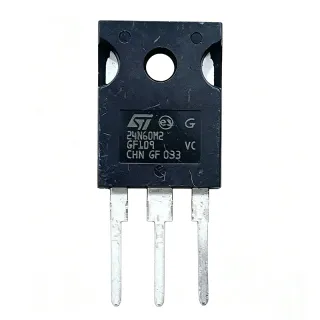
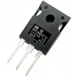
| Encapsulamento | TO-247 |
| Tipo de montagem | Through Hole |
| Avalanche Rating | Yes |
| dv/dt Capability | High |
| Status RoHS | Compliant |
| Isolation | Fully isolated |
Configuração de pinos do STW12N60M2
| Pino 1 | Gate — Gate terminal for controlling the MOSFET |
| Pino 2 | Drain — Drain terminal, connected to the load |
| Pino 3 | Source — Source terminal, connected to ground |
Área de Operação Segura
Aplicações típicas
STW12N60M2 é adequado para 6 aplicaçãos: Switch-Mode Power Supplies (SMPS), Power Factor Correction (PFC), LED Lighting Drivers, Solar Inverters, Motor Drives, Uninterruptible Power Supplies (UPS).
Switch-Mode Power Supplies (SMPS)
The STW12N60M2 is ideal for SMPS due to its 600V rating and low on-resistance, enabling efficient power conversion. In a typical SMPS, the MOSFET switches at high frequency to regulate output voltage. Its low gate charge reduces switching losses, improving overall efficiency. The TO-247 package ensures adequate heat dissipation for continuous operation. Compared to IGBTs, the MOSFET offers faster switching, making it suitable for high-frequency designs.
Recomendado
Power Factor Correction (PFC)
In PFC circuits, the STW12N60M2 handles high voltage and current with low losses, improving power factor. Its fast body diode reduces reverse recovery losses, enhancing efficiency. The device's avalanche rating ensures robustness during transient conditions. The low gate charge allows high-frequency operation, reducing the size of magnetic components. The TO-247 package provides thermal stability for continuous PFC operation.
Recomendado
LED Lighting Drivers
The STW12N60M2 is suitable for LED drivers requiring high voltage and efficiency. Its low on-resistance minimizes conduction losses, improving driver efficiency. The fast switching speed enables compact designs with smaller inductors. The device's robustness ensures reliable operation in harsh environments. The TO-247 package allows for effective heat management in high-power LED applications.
Recomendado
Solar Inverters
In solar inverters, the STW12N60M2 handles high DC voltages and converts them to AC efficiently. Its low RDS(on) reduces conduction losses, improving inverter efficiency. The high dv/dt capability ensures reliable switching in harsh conditions. The device's avalanche rating protects against overvoltage transients. The TO-247 package provides excellent thermal performance for continuous operation.
Recomendado
Motor Drives
The STW12N60M2 is used in motor drives for its high voltage and current handling. Its fast switching reduces losses, improving motor drive efficiency. The low gate charge enables high-frequency PWM control. The device's robustness ensures reliable operation in industrial environments. The TO-247 package allows for effective heat dissipation in high-power motor drives.
Recomendado
Uninterruptible Power Supplies (UPS)
In UPS systems, the STW12N60M2 handles high power conversion with efficiency. Its low on-resistance reduces losses, improving battery life. The fast switching speed enables compact inverter designs. The device's avalanche rating ensures reliability during load transients. The TO-247 package provides thermal stability for continuous UPS operation.
Recomendado
Resumo dos produtos recomendados
Dados de referência de engenharia para STW12N60M2 — comparação, orientação de projeto e informações de conformidade.
Guia de seleção
Comparação com alternativas
| Parâmetro | Este produto | STW12N60M2-1 | IPW60R070P6 | FCH12N60 |
|---|---|---|---|---|
| Package | TO-247 | TO-220 | TO-247 | TO-247 |
| Brand | STMicroelectronics | STMicroelectronics | Infineon | onsemi |
| Drain-Source Voltage (VDS) | 600 V | 600 V | 600 V | 600 V |
| Continuous Drain Current (ID) | 12 A | 12 A | 12 A | 12 A |
| On-Resistance (RDS(on)) | 0.38 ohm | 0.38 ohm | 0.07 ohm | 0.38 ohm |
| Gate Charge (Qg) | 30 nC | 30 nC | 45 nC | 35 nC |
| Avalanche Rating | Yes | Yes | Yes | Yes |
| RoHS Compliant | Yes | Yes | Yes | Yes |
Principais diferenciais
- Low on-resistance of 0.38 ohm (vs IPW60R070P6)
- Low gate charge of 30 nC (vs IPW60R070P6)
- MDmesh M2 technology (vs FCH12N60)
Notas de projeto
The STW12N60M2 in TO-247 package can dissipate significant power. For a 12A load at 0.38 ohm, conduction losses are approximately 55W. Ensure adequate heatsinking with thermal resistance below 1°C/W to keep junction temperature within limits. Use thermal paste and proper mounting torque.
For high-frequency switching, keep gate drive traces short and use a gate resistor (typically 10-100 ohm) to control switching speed and reduce EMI. Place a 100nF ceramic capacitor close to the gate-source pins. Ensure the source pin has a low-inductance path to ground.
Do not exceed the maximum gate-source voltage (typically ±20V). Use a gate driver with proper voltage levels. Ensure the MOSFET is fully turned on with VGS of 10V to achieve lowest RDS(on). Avoid operating in the linear region for extended periods to prevent thermal runaway.
Informações de conformidade
RoHS compliant per STMicroelectronics datasheet. Not AEC-Q100 qualified.