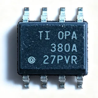
MC1458DR - Dual 1MHz Op Amp, ±15V, 8-SOIC | Texas Instruments
Артикул: MC1458DR ✓ Активен| Кол-во | Цена за ед. | Итого |
|---|---|---|
| 1 | $0.55 | $0,55 |
| 10 | $0.46 | $4,60 |
| 100 | $0.36 | $36,00 |
| 500 | $0.28 | $140,00 |
| 1.000 | $0.23 | $230,00 |
| 2.500 | $0.19 | $475,00 |
MC1458DR Обзор
An operational amplifier (op amp) is a high-gain DC-coupled voltage amplifier with differential inputs and a single-ended output. In the system hierarchy, the MC1458DR sits as a general-purpose linear IC under amplifier ICs, which itself belongs to the broader family of analog signal-conditioning components and integrated circuits. The MC1458DR is specifically a dual-channel, internally compensated design that requires no external frequency-compensation capacitor, simplifying PCB layout versus discrete-transistor op-amp implementations.
Key features include short-circuit protection on the output stage, low power consumption of approximately 1.7 mA per amplifier at plus/minus 15 V, no latch-up, and wide common-mode plus differential voltage ranges. The two channels share a single bias network, giving matched DC behavior that suits difference amplifiers, active filters, and dual-channel transducer signal chains. Each channel is a complete bipolar op amp with internal compensation, allowing the part to be used as a direct functional replacement for legacy 1458-family designs with no circuit changes.
Architecturally, the MC1458DR uses a classic bipolar transistor input stage with an active load, a Darlington intermediate stage, and a class-AB complementary emitter-follower output, mirroring the topology of the uA741 but with two channels on one die. The dual-die design eliminates the need for an external compensation capacitor on each channel; instead, the internal capacitor is trimmed during wafer test. This mature architecture trades raw speed for excellent DC accuracy, low input bias current relative to JFET alternatives, and predictable behavior over the full 0 to 70 degrees C commercial temperature range.
Typical applications include active filtering, transducer signal conditioning, instrumentation front ends, integrators and comparators, audio preamplifiers, and general-purpose dual-channel amplification in industrial controls and consumer electronics. The matched pair also makes it well-suited for differential amplifiers driving downstream ADCs.
When designing with this part, observe the absolute maximum differential input voltage of plus/minus 30 V and ensure the input common-mode range is respected to avoid phase inversion. Bypass supplies with a 0.1 uF ceramic capacitor close to the VCC+ and VCC- pins to prevent oscillation in unity-gain buffer configurations.
This page synthesizes distributor pricing, drop-in replacement candidates for the dual 1458 pinout, and practical design notes not consolidated in the manufacturer datasheet.
Аналоги без доработки для MC1458DR — тот же корпус, pin-to-pin совместимость. Компоненты в других корпусах, требующие переработки PCB, исключены.
Инструмент быстрого сравнения — выберите альтернативные компоненты для сравнения бок о бок:
MC1458DGKR
✅ Прямая замена ⚠️ Характеристики не проверены📋 Справочный аналог (нет в каталоге)
MC1558DR
✅ Прямая замена ⚠️ Характеристики не проверены📋 Справочный аналог (нет в каталоге)
NJM1458D
✅ Прямая замена ⚠️ Характеристики не проверены📋 Справочный аналог (нет в каталоге)
MC1458DR Максимальные параметры и электрические характеристики
| Manufacturer | Texas Instruments |
| Part Family | MC1458 |
| Amplifier Type | General Purpose, Dual Channel |
| Number of Channels | 2 |
| Slew Rate | 0.5 V/us (typical) |
| Gain Bandwidth Product | 1 MHz |
| Input Offset Voltage | 1 mV (typical at 25 C) |
| Input Bias Current | 30 nA (typical) |
| Supply Voltage Range (Dual) | plus/minus 5 V to plus/minus 15 V |
| Supply Voltage Range (Single) | 10 V to 30 V |
| Supply Current per Channel | 1.7 mA (typical at plus/minus 15 V) |
| Диапазон рабочих температур | 0 C to +70 C |
| Корпус | 8-SOIC (D) |
| Число выводов | 8 |
| Short-Circuit Protection | Yes |
| Latch-Up | None |
| Frequency Compensation | Internal (no external cap required) |
| Тип монтажа | Surface Mount |
| Статус RoHS | See TI product page |
| Pin-Compatible Cross | MC1558, N5558, S5558 |
Конфигурация выводов MC1458DR
| Контакт 1 | OUTPUT A — Channel A op-amp output |
| Контакт 2 | INVERTING INPUT A — Channel A inverting input |
| Контакт 3 | NON-INVERTING INPUT A — Channel A non-inverting input |
| Контакт 4 | VCC- — Negative supply voltage (or GND for single supply) |
| Контакт 5 | NON-INVERTING INPUT B — Channel B non-inverting input |
| Контакт 6 | INVERTING INPUT B — Channel B inverting input |
| Контакт 7 | OUTPUT B — Channel B op-amp output |
| Контакт 8 | VCC+ — Positive supply voltage |
Типичное применение
MC1458DR подходит для 6 применениеs: Active Filter Circuits, Transducer Signal Conditioning, Audio Preamplifier Stages, Integrator and Comparator Circuits, Differential Amplifier Front Ends, Industrial Control Loop Signal Chain.
Active Filter Circuits
The MC1458DR's matched dual-channel architecture, 1 MHz gain bandwidth product, and low 30 nA input bias current make it a strong fit for Sallen-Key and multiple-feedback active filter designs. Each channel operates independently but shares matched DC characteristics, which is ideal for cascaded low-pass and high-pass stages that need consistent gain. The internally compensated op amp is unity-gain stable, so active filter circuits up to several hundred kHz need no external compensation components. The bipolar input stage accepts ground-referenced signals from sensors and transducers with predictable offset behavior. Compared with single-channel alternatives, the dual MC1458DR saves board space by placing two filter poles in one SOIC footprint while drawing only 1.7 mA per channel.
Рекомендуется
Transducer Signal Conditioning
Strain gauges, thermocouples, and bridge-type pressure sensors benefit from the MC1458DR's instrumentation front-end capability when configured as a two-op-amp or three-op-amp instrumentation amplifier. The 1 MHz GBW is sufficient for slow-changing transducer outputs up to several kHz, and the dual supply voltage range from plus/minus 5 V to plus/minus 15 V supports industrial 24 V analog rails. The bipolar input stage offers low input bias current (about 30 nA) that minimizes error when driving high-impedance sensor networks. Both channels are matched, so the differential gain error is dominated by external resistor tolerance rather than the IC. Compared with discrete op-amp designs, the MC1458DR simplifies PCB layout and reduces BOM count for low-frequency transducer signal chains.
Рекомендуется
Audio Preamplifier Stages
Audio preamplifier circuits operating in the 20 Hz to 20 kHz band map well to the MC1458DR's 1 MHz gain bandwidth product and 0.5 V/us slew rate, providing clean amplification of microphone, line-level, and instrument pickup signals. The dual channel allows a single 8-SOIC to deliver stereo preamp gain, saving PCB area in consumer audio equipment. The bipolar input stage presents low noise relative to vintage single-supply op amps, and the plus/minus 15 V supply range supports high-fidelity analog signal swing. Internal short-circuit protection on each output makes the device rugged against accidental shorts to ground in prototyping. Compared with low-cost single-channel audio op amps, the MC1458DR provides matched left/right channel performance in one package.
Рекомендуется
Integrator and Comparator Circuits
Integrator and comparator applications use the MC1458DR's wide common-mode input range and internal compensation to build accurate waveform generators, ramp generators, and analog computing blocks. Channel A configured as an integrator with a 0.1 uF timing capacitor and 100 kohm input resistor delivers a 1 ms time constant, well within the op amp's 0.5 V/us slew rate limit. Channel B wired as a comparator with hysteresis provides a clean digital-level output for control loops. The wide supply range of plus/minus 5 V to plus/minus 15 V lets the integrator swing close to the rails without saturation. Compared with single-channel op amps, the dual MC1458DR builds complete function generators in a single SOIC package.
Рекомендуется
Differential Amplifier Front Ends
The two matched channels inside the MC1458DR are well suited to differential amplifier topologies that reject common-mode noise on long sensor cables or 4-20 mA current loops. When configured as a single-op-amp differential amplifier with four matched resistors, the op amp's wide common-mode input range (plus/minus 12 V typical at plus/minus 15 V supply) handles industrial signal levels without saturating the input stage. The 1 MHz GBW maintains differential signal integrity up to several hundred kHz, sufficient for vibration and acoustic analysis. Both channels share the same die and bias network, so DC offset drift tracks between channels, simplifying calibration. Compared with discrete transistor differential pairs, the MC1458DR delivers reliable matched performance over the full 0 to 70 C commercial range.
Рекомендуется
Industrial Control Loop Signal Chain
Industrial control loops operating on 24 V analog rails use the MC1458DR for current-loop receivers, voltage-to-current converters, and proportional-integral (PI) controller implementations. The op amp's wide plus/minus 15 V supply tolerance and high common-mode rejection make it tolerant of noisy factory environments with switched-mode power supplies. The dual channel allows one IC to handle both proportional and integral paths of a PI controller, reducing board area in compact PLC and motor-drive modules. Short-circuit-protected outputs survive miswiring during commissioning. Compared with modern CMOS op amps, the MC1458DR's bipolar input stage offers robust behavior with high-impedance feedback networks found in 4-20 mA loops.
Рекомендуется
Сводка рекомендуемых товаров
Справочные инженерные данные для MC1458DR — сравнение, рекомендации по проектированию и информация о соответствии.
Руководство по выбору
Сравнение с аналогами
| Параметр | Этот товар | MC1458DGKR | MC1558DR | NJM1458D |
|---|---|---|---|---|
| Brand | Texas Instruments | Texas Instruments | Texas Instruments | NJR (Nippon Radio) |
| Package | 8-SOIC (D) | 8-SOIC (D) - same | 8-SOIC (D) - same | 8-SOIC (D) - same |
| Gain Bandwidth Product | 1 MHz | 1 MHz | 1 MHz | 1 MHz |
| Slew Rate | 0.5 V/us | 0.5 V/us | 0.5 V/us | 0.5 V/us |
| Operating Temperature Range | 0 C to +70 C | 0 C to +70 C | -55 C to +125 C | -20 C to +75 C (typical) |
| Supply Voltage (Dual) | plus/minus 5 V to plus/minus 15 V | plus/minus 5 V to plus/minus 15 V | plus/minus 5 V to plus/minus 15 V | plus/minus 5 V to plus/minus 15 V |
| Short-Circuit Protection | Yes | Yes | Yes | Yes |
| Internal Compensation | Yes (no external cap) | Yes | Yes | Yes |
Ключевые отличия
- Internally compensated dual op amp in industry-standard 8-SOIC (против LM358)
- Wide plus/minus 15 V supply tolerance for industrial rails (против TL072CP)
- Pin-exact replacement for legacy 1458 family designs (против MC1458P (DIP-8 version))
Заметки по проектированию
The MC1458DR's input common-mode range does not extend to the negative supply rail reliably across all samples; if your design requires true single-supply operation down to 0 V input, consider a modern single-supply op amp such as the LM358 or TLV2372 instead. When using plus/minus 15 V supplies, keep input voltages within plus/minus 12 V common-mode to avoid input stage saturation. Source impedance above 10 kohm will multiply the 30 nA input bias current into significant offset voltage, so use lower-impedance feedback networks where precision matters.
Place a 0.1 uF ceramic bypass capacitor as close as possible to pins 4 (VCC-) and 8 (VCC+) to prevent oscillation in unity-gain buffer configurations. For dual-supply boards, use a separate ground return path for high-current loads to avoid coupling noise into the op amp's signal ground. Route input traces away from the output traces on the same channel to minimize parasitic feedback that can degrade phase margin. Keep the copper area under the SOIC body minimal to reduce thermal stress and to ensure compliance with the SOIC exposed-pad recommendation.
The MC1458DR's quiescent dissipation at plus/minus 15 V is about 50 mW per channel (1.7 mA at 30 V total), well within the 8-SOIC's thermal limits and unlikely to require a heatsink. However, in enclosed industrial environments with ambient temperatures above 60 C, verify that the maximum junction temperature (150 C absolute maximum) is not approached, especially when the channels drive sustained near-maximum output swing. Adding small copper pours on the VCC pins helps share heat away from the die.
The internally compensated 30 pF Miller capacitor makes the MC1458DR unity-gain stable but limits its useful gain-bandwidth region to about 1 MHz. For applications above 100 kHz of signal bandwidth, derate the achievable closed-loop gain; for example, at 100 kHz the maximum useful gain is about 10. Driving large capacitive loads (>1000 pF) directly at the output can cause phase-margin loss; isolate capacitive loads with a 50 to 100 ohm series resistor if pulse response is critical.
Информация о соответствии
RoHS and REACH compliance confirmed per TI MC1458 product page; the DR suffix indicates Pb-free 8-SOIC finish. Halogen-free status should be confirmed on the TI datasheet ordering info table since this was not stated in the verified web data.