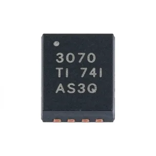
INA129PG4 Precision Instrumentation Amplifier | Texas Instruments
MPN: INA129PG4 ✓ NakahandaINA129PG4 Ulas
An instrumentation amplifier is a specialized amplifier category designed to amplify the difference between two input signals while rejecting common-mode voltage. The instrumentation-amplifier hierarchy includes differential amplifiers, analog signal-conditioning ICs, amplifiers, and semiconductor devices. Its three-op-amp architecture and current-feedback input stage make it suitable for sensors and measurement systems in which small differential signals are superimposed on a larger common-mode voltage.
Key characteristics include 4 V/µs slew rate, low offset drift of 0.5 µV/5°C maximum, and input protection to +40 V. The wide supply range extends to +18 V, while the input architecture retains a bandwidth of 200 kHz at a gain of 100. These characteristics support precision bridge, current-shunt, and sensor-amplification circuits without requiring a high-power amplifier.
The INA129PG4 uses a versatile three-op-amp architecture. A single external resistor establishes the gain, allowing the same device to serve multiple measurement ranges. Its current-feedback input circuitry is designed to preserve usable bandwidth at higher closed-loop gains. The combination of low supply current, low offset, high CMRR, and protected inputs makes it especially useful for compact, low-power measurement instruments.
Typical applications include bridge-sensor signal conditioning, portable instrumentation, industrial process monitoring, medical measurement interfaces, and low-level differential-signal acquisition. Its protected inputs can simplify front-end design when the source may produce transient overvoltage, although the complete application must still satisfy the device's absolute maximum ratings.
For a new PCB, use the manufacturer pin-description table to assign all eight DIP connections and place the gain resistor close to the gain-setting pin. Check supply voltage, common-mode input range, input impedance, and output swing at the intended gain before finalizing component values.
This product page combines the manufacturer specifications, package details, replacement analysis, parameter comparisons, and practical design guidance to help engineers evaluate the INA129PG4 before committing a precision measurement circuit to production.
Mga alternatibo na pwedeng ilagay na INA129PG4 — parehas na package, pin-to-pin na katugmang. Hindi kasama ang mga bahagi ng iba't-ibang package na nangangailangan ng pagpapaayos ng PCB.
Variante sa Seri na ito
Katulad na modelo sa serye na katugma sa pagpasok INA129PG4 (parehas na form factor at footprint) — pagkakaiba sa Architecture, Input Protection, Package, Maximum Offset Drift, Maximum Offset Voltage.
INA129P
✅ Drop-In ⚠️ Mga Talaan Hindi NaiwerikmoMagkontak para sa presyo
Tingnan ang Datasheet →INA128P
✅ Drop-In ⚠️ Mga Talaan Hindi NaiwerikmoMagkontak para sa presyo
Tingnan ang Datasheet →INA129PG4 Mga Pinakamataas na Rating at Electrical Characteristics
| Amplifier Type | Instrumentation amplifier |
| Number of Circuits | 1 circuit |
| Packhaging | 8-PDIP (0.300 inch, 7.62 mm pitch) |
| Packaging | Tube |
| Gain-Bandwidth Product | 1.3 MHz |
| Bandwidth at Gain 100 | 200 kHz |
| Slew Rate | 4 V/µs |
| Kuru-kuryente ng Pagbibigay | 700 µA |
| Maximum Supply Voltage | +18 V |
| Maximum Offset Voltage | 50 µV |
| Maximum Offset Drift | 0.5 µV/5°C |
| Maximum Input Bias Current | 5 nA |
| Minimum Common-Mode Rejection | 120 dB |
| Maximum Protected Input Voltage | +40 V |
| Input Protection | Protected to +40 V |
| Architecture | Three-op-amp instrumentation amplifier with current-feedback input circuitry |
| Uri ng Pagpapasok | Through-hole DIP |
Gabay sa Pin Configuration ng INA129PG4 8-pdip (0.300 inch, 7.62 mm pitch)
Pin configuration para sa INA129PG4 (8-pdip (0.300 inch, 7.62 mm pitch) package). Ang analog component na ito ay may input, output, at power supply pins. Sumangguni sa datasheet ng manufacturer para sa offset null, compensation, at enable pin configurations. Perpekto para sa signal conditioning at amplifier circuits.

Wala ng detalyadong pinout data na magagamit para sa INA129PG4.
Sumangguni sa datasheet para sa buong pin configuration.
Tipikal na mga Gamit
INA129PG4 ay nararapat para sa 6 aplikasyons: Bridge Sensor Signal Conditioning, Portable Medical Instrumentation, Industrial Process Measurement, Current-Shunt Monitoring, Low-Level Data Acquisition, Environmental Sensor Interface.
Bridge Sensor Signal Conditioning
The INA129PG4 fits bridge-based pressure, strain, and force measurements where the useful signal is small and differential. Its 120 dB minimum common-mode rejection helps separate the bridge differential from the common-mode voltage present at both inputs, while 50 µV maximum offset voltage limits error near the output null. A single external resistor sets the gain, allowing the design to be adapted across different bridge sensitivities. The 4 V/µs slew rate also supports dynamic measurements better than a slow precision-only amplifier. Verify the bridge excitation voltage, input common-mode range, output swing, and gain before committing the circuit.
Inirekomenda
Portable Medical Instrumentation
The INA129PG4 is suitable for low-level biomedical measurement front ends that require good common-mode rejection and low offset error. Its 700 µA supply current supports compact, battery-operated equipment, while the 5 nA maximum input bias current is favorable for high-impedance sensor interfaces. The protected inputs extend to +40 V, adding useful transient tolerance when connected to patient-connected or externally routed circuitry. Signal-chain safety and applicable medical-device requirements remain system-level responsibilities. The designer should verify input bias behavior, common-mode limits, output range, and noise performance for the selected gain and bandwidth.
Inirekomenda
Industrial Process Measurement
The INA129PG4 can condition low-level differential process signals where long sensor wiring may introduce substantial common-mode voltage. Its 120 dB minimum CMRR improves rejection of that shared voltage, and the 1.3 MHz gain-bandwidth product gives adequate bandwidth for many sensor and control-loop signals. The three-op-amp architecture supports simple gain selection with one external resistor. For industrial deployment, verify the available input common-mode range, supply voltage, output swing, and behavior during sensor faults. The +40 V input protection rating can simplify transient handling, although protection should not be treated as a substitute for proper surge-protection design.
Inirekomenda
Current-Shunt Monitoring
The INA129PG4 is appropriate for measuring the small voltage generated across a current shunt in power-conversion and battery systems. Its low 50 µV maximum offset voltage improves measurement resolution near zero current, and 120 dB minimum CMRR rejects supply ripple or switching-node voltage common to both shunt terminals. A single gain-setting resistor simplifies adaptation across different shunt ranges. Designers must confirm that the shunt voltage stays within the input common-mode range and that the amplifier output remains within its swing limits at maximum load current. Input filtering and Kelvin routing are important for accurate high-current measurements.
Inirekomenda
Low-Level Data Acquisition
The INA129PG4 works as the analog front end for low-level data-acquisition channels that require accurate differential sensing without high quiescent power. Its 700 µA supply current, 1.3 MHz gain-bandwidth product, and 4 V/µs slew rate provide a practical balance between precision and responsiveness. The common-mode rejection and low offset reduce errors in thermocouple, strain, and pressure channels. Choose the external gain resistor and decoupling network from the manufacturer application guidance, and confirm that the selected gain does not force the output outside its allowable swing. Place the gain resistor close to the device to reduce susceptibility to pickup and board contamination.
Inirekomenda
Environmental Sensor Interface
The INA129PG4 is suitable for environmental sensors that present a small differential output over a larger common-mode voltage, including resistive and bridge-based sensing elements. Its 120 dB minimum CMRR helps maintain measurement accuracy when the sensor is not referenced to ground, and the low 700 µA supply current benefits remote or energy-limited nodes. The 50 µV maximum offset and 5 nA maximum input bias current support low-level signal integrity. Check the sensor excitation scheme, input impedance, common-mode range, and permitted temperature range before deployment. For long cable runs, add appropriate input protection and filtering while retaining low-noise signal paths.
Inirekomenda
Buod ng mga Inirekomendang Produkto
Impormasyon ng Talumpati sa Engineering for INA129PG4 — ikabit, gabay sa disenyo, at impormasyon ng pagsunod sa kautusan.
Paunawang Hanapin
Ikabit sa Mga Alternatibo
| Parametro | Ito ang Producto | INA129P | INA128P |
|---|---|---|---|
| Brand | Texas Instruments | Texas Instruments | Texas Instruments |
| Package | 8-PDIP | 8-PDIP - same package | 8-PDIP - same package |
| Amplifier Type | Instrumentation amplifier | Instrumentation amplifier | Instrumentation amplifier |
| Number of Circuits | 1 circuit | 1 circuit | 1 circuit |
| Gain-Bandwidth Product | 1.3 MHz | 1.3 MHz | 350 kHz |
| Supply Current | 700 µA | 700 µA | 500 µA |
| Slew Rate | 4 V/µs | 4 V/µs | 2 V/µs |
Pangunahing mga Pagkakaiba
- Higher gain-bandwidth product than the lower-bandwidth INA12x alternative (kumpara saINA128P)
- Protected inputs for transient-tolerant measurement interfaces (kumpara saINA128P)
- Same-package ordering option preserves the original footprint (kumpara saINA129P)
Talaan ng Disenyo
Place the external gain-setting resistor close to the corresponding INA129PG4 pin and route the differential input pair as a matched, compact pair. Keep high-impedance input traces away from switching nodes, inductors, and digital return paths. Use a solid ground reference beneath the analog section and follow the manufacturer layout guidance for bypass-capacitor placement. These steps minimize parasitic pickup, board contamination effects, and gain-error contributions that can be significant in a low-offset amplifier.
Decouple the supply pins with the capacitance and ESR range specified in the manufacturer datasheet, and place the devices physically close to the INA129PG4. The amplifier's stated 700 µA supply current does not include every load presented by the gain resistor and external circuit. Confirm the complete rail voltage and output headroom at the highest input and lowest load conditions. Input protection to +40 V does not permit operation above the device's separate absolute maximum ratings.
Do not select the INA129PG4 using only its 50 µV maximum offset specification. At high closed-loop gain, resistor tolerance, bias-current error, output-range restrictions, and input common-mode limits can dominate total measurement error. Use the manufacturer gain equation to calculate the external resistor, then check the resulting output voltage at both input extremes. For shunts and bridges, use Kelvin routing where available to avoid adding copper and connector resistance to the measured voltage.
Impormasyon ng Pagsunod sa Kautusan
No definitive compliance declaration was identified in the referenced product and ordering information. The INA129PG4 is an industrial instrumentation amplifier rather than an automotive-qualified device.