پاور مینجمنٹ
ذیلی زمرے
مصنوعات (2,800+)
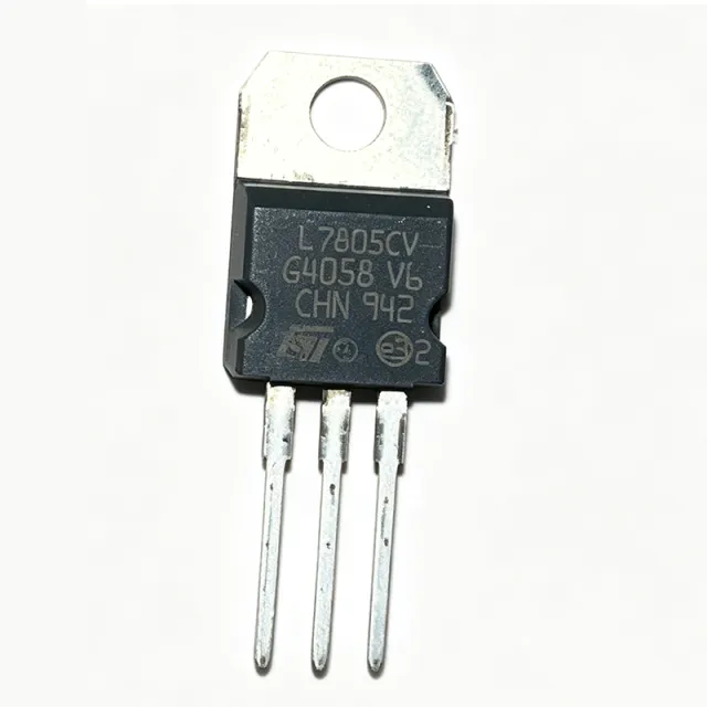
L7805CV - 5V 1.5A Positive Voltage Regulator | STMicroelectronics
The STMicroelectronics L7805CV is a fixed positive voltage regulator that provides a stable 5V output with a maximum output current of 1.5A. It is housed in a TO-220 package, which is widely used for through-hole mounting and offers excellent thermal performance. The device operates over an input voltage range of 7V to 35V, making it suitable for a variety of power supply applications. Data verified as of 2026-08-05. A linear voltage regulator is a type of voltage regulator that maintains a constant output voltage by dissipating excess power as heat. The L7805CV is a member of the 78xx series of fixed linear regulators, which are part of the broader category of voltage regulators within power management ICs. Linear regulators are known for their simplicity, low noise, and fast transient response, making them ideal for applications where clean and stable power is required. Key features of the L7805CV include internal current limiting, thermal shutdown, and safe-area compensation, which protect the device and the load from damage. The output voltage is fixed at 5V with a typical accuracy of ±2% (4.8V to 5.2V). The dropout voltage is typically 2V at 1A output current, meaning the input must be at least 7V for proper regulation. The device also offers a ripple rejection of 62 dB at 120 Hz, ensuring minimal AC ripple on the output. The L7805CV is built using a bipolar junction transistor (BJT) process, which provides robust performance and high reliability. The TO-220 package includes a metal tab that can be connected to a heatsink for improved thermal dissipation. The thermal resistance from junction to case is 5°C/W, and the maximum junction temperature is 150°C. This allows the device to handle power dissipation up to 15W with adequate heatsinking. Typical applications include power supplies for microcontrollers, logic circuits, and analog circuits, as well as battery chargers and instrumentation. The wide input voltage range and high output current make it versatile for both low-power and moderate-power applications. In a typical design, the L7805CV is used with input and output capacitors (0.33µF and 0.1µF) to ensure stability and reduce noise. When designing with the L7805CV, it is important to consider the power dissipation and thermal management. For example, at VIN=12V, VOUT=5V, and 1A load, the power dissipation is 7W, which requires a heatsink to keep the junction temperature within safe limits. The input capacitor should be placed close to the input pin, and the output capacitor should be placed close to the output pin to minimize parasitic inductance. This page synthesizes distributor pricing, drop-in alternatives, and practical design notes not found in the STMicroelectronics datasheet, providing engineers with a comprehensive resource for selecting and using the L7805CV.

L7980TR - 2A Step-Down Switching Regulator | STMicroelectronics
The STMicroelectronics L7980TR is a step-down switching regulator capable of delivering up to 2A output current. It operates from an input voltage range of 4.5V to 28V and provides an adjustable output voltage down to 0.6V. The device is available in an 8-pin SOIC package (SO-8) and is designed for high-efficiency power conversion in a wide range of applications. A step-down switching regulator, also known as a buck converter, is a type of DC-DC converter that efficiently reduces a higher input voltage to a lower output voltage. Unlike linear regulators, which dissipate excess power as heat, switching regulators use an inductor, a switch, and a diode to transfer energy in discrete pulses, achieving efficiencies often above 90%. This makes them essential in battery-powered and high-current applications where power loss must be minimized. The L7980TR belongs to the broader category of power management ICs, specifically within the DC-DC converter family. Key features of the L7980TR include a 250 kHz fixed switching frequency, an internal power MOSFET with a low RDS(on) of 250 mOhm, and a high-efficiency design that minimizes external component count. The device also includes an internal compensation network, soft-start, and thermal shutdown protection, simplifying the design process. The adjustable output voltage, set by an external resistor divider, allows flexibility for various output levels. The L7980TR utilizes a current-mode control architecture, providing fast transient response and stable operation over a wide range of load currents. The internal compensation eliminates the need for external compensation components, reducing board space and design complexity. The device's high switching frequency allows the use of small, low-cost inductors and capacitors, further reducing the overall solution footprint. Typical applications include point-of-load (POL) converters for FPGAs, DSPs, and microcontrollers, as well as distributed power systems, battery chargers, and industrial control systems. The wide input voltage range makes it suitable for 12V and 24V industrial buses, while the high efficiency extends battery life in portable devices. When designing with the L7980TR, ensure proper PCB layout with short, wide traces for high-current paths and adequate grounding. The exposed pad (if present) should be connected to the ground plane for thermal dissipation. Input and output capacitors should be placed close to the IC to minimize parasitic inductance and ensure stable operation.
L7981TR - 2A Step-Down Switching Regulator | STMicroelectronics
The STMicroelectronics L7981TR is a step-down switching regulator capable of delivering up to 2A output current from an input voltage range of 4.5V to 28V. Housed in a compact 8-pin SOIC (SO-8) package, this device integrates a high-side power MOSFET and provides a fixed 3.3V output voltage, making it suitable for a wide range of power conversion applications. A step-down switching regulator, also known as a buck converter, is a type of DC-DC converter that efficiently reduces a higher input voltage to a lower output voltage. Unlike linear regulators, which dissipate excess power as heat, switching regulators use an inductor and a switch to transfer energy in discrete pulses, achieving high efficiency, especially when the input-to-output voltage difference is large. The L7981TR belongs to the broader category of power management ICs, specifically within the DC-DC converter family, and is designed for applications requiring reliable and efficient voltage step-down. Key features of the L7981TR include a 2A output current capability, a wide input voltage range of 4.5V to 28V, and a fixed 3.3V output voltage. The device operates at a switching frequency of 250 kHz, which balances efficiency and component size. It also features internal current limiting, thermal shutdown, and an enable pin for power sequencing. The SO-8 package offers a compact footprint with a thermal resistance of approximately 62.5 C/W, allowing for moderate power dissipation without external heatsinking. The L7981TR utilizes a current-mode control architecture, which provides fast transient response and simplifies loop compensation. The integrated high-side MOSFET reduces external component count, while the internal compensation network minimizes design complexity. The device's high efficiency, typically above 85% for 12V to 3.3V conversion at 1A load, makes it suitable for battery-powered and industrial applications where power loss must be minimized. Typical applications include point-of-load (POL) converters for microcontrollers and FPGAs, industrial control systems, and distributed power architectures. The wide input range allows operation from 5V USB supplies, 12V industrial rails, and 24V bus systems, providing design flexibility across multiple platforms. When designing with the L7981TR, ensure proper input and output capacitor selection to maintain stability and minimize output ripple. The enable pin allows sequenced power-up in multi-rail systems, which is critical for processors requiring specific rail sequencing. Additionally, the thermal pad on the SO-8 package should be connected to a sufficient copper area for heat dissipation.
L7983TR - 38V 3A Step-Down Switching Regulator | STMicroelectronics
The STMicroelectronics L7983TR is a step-down switching regulator (buck converter) capable of delivering up to 3A output current from an input voltage range of 4.5V to 38V. Housed in a compact 8-pin SOIC (SO-8) package, this device integrates a high-side power MOSFET and provides a fixed 250kHz switching frequency, making it suitable for a wide range of power conversion applications. A buck converter, also known as a step-down regulator, is a type of DC-DC converter that efficiently reduces a higher input voltage to a lower output voltage. It operates by rapidly switching a transistor on and off, storing energy in an inductor during the on-time and releasing it to the load during the off-time. This switching action achieves high efficiency, typically above 85%, which is critical in battery-powered and thermally constrained systems. The L7983TR belongs to the family of switching regulators, which are a subset of power management ICs, and is designed to replace less efficient linear regulators in applications where power dissipation is a concern. Key features of the L7983TR include a 3A output current capability, a wide input voltage range of 4.5V to 38V, and a fixed 250kHz switching frequency. The device offers internal compensation, simplifying the design by reducing external component count. It also includes overcurrent protection, thermal shutdown, and an enable pin for power sequencing. The high switching frequency allows for the use of small inductors and capacitors, reducing the overall solution footprint. The L7983TR utilizes a current-mode control architecture, which provides fast transient response and stable operation over a wide range of load conditions. The integrated high-side MOSFET minimizes external component count and reduces conduction losses. The device is designed for high efficiency, with a typical efficiency of 90% at 12V input and 5V output at 2A load. The internal soft-start function limits inrush current during startup, preventing output overshoot. Typical applications include industrial power supplies, automotive systems, distributed power architectures, and point-of-load (POL) converters. The wide input voltage range makes it suitable for 12V and 24V bus systems, while the 3A output current can power FPGAs, microcontrollers, and sensors. The enable pin allows for power sequencing in multi-rail systems, ensuring proper startup order. When designing with the L7983TR, ensure proper PCB layout with short, wide traces for high-current paths and adequate ground plane for thermal management. The inductor and output capacitor should be placed close to the IC to minimize parasitic inductance. The feedback resistor divider should be placed away from the inductor to avoid noise coupling. The thermal pad (if present) should be soldered to a large copper area for heat dissipation.
L7985TR - 2A Step-Down Switching Regulator | STMicroelectronics
The STMicroelectronics L7985TR is a step-down switching regulator capable of delivering up to 2A output current. It operates from an input voltage range of 4.5V to 38V, making it suitable for a wide variety of industrial and automotive applications. The device is available in a compact HSOP-8 package, which is designed for surface-mount assembly and provides excellent thermal performance. A step-down switching regulator, also known as a buck converter, is a type of DC-DC converter that efficiently reduces a higher input voltage to a lower output voltage. Unlike linear regulators, which dissipate excess power as heat, switching regulators use an inductor and a switch to transfer energy in a controlled manner, achieving high efficiency. The L7985TR belongs to the family of voltage regulators, which are essential components in power management systems, converting unregulated power sources into stable, usable voltages for electronic circuits. Key features of the L7985TR include a 250 kHz fixed switching frequency, an internal power MOSFET, and a current-mode control architecture. The device offers a typical efficiency of over 85% at full load, reducing power loss and heat generation. It also includes a built-in soft-start function to limit inrush current during startup, and a thermal shutdown protection to prevent damage from overheating. The output voltage is adjustable from 0.6V to the input voltage, providing flexibility for various design requirements. The L7985TR utilizes a current-mode control scheme, which provides fast transient response and simplifies loop compensation. The internal power switch is rated for a peak current of 3A, ensuring reliable operation under load transients. The device also features a low quiescent current of 2.5 mA, which is beneficial for battery-powered applications. The HSOP-8 package has a thermal resistance of 40°C/W, allowing for efficient heat dissipation in moderate power applications. Typical applications for the L7985TR include point-of-load converters, distributed power systems, industrial control systems, and automotive power supplies. Its wide input voltage range and high efficiency make it ideal for converting 12V or 24V bus voltages to lower logic rails. The device is also suitable for LED lighting applications, where constant current regulation is required. When designing with the L7985TR, it is important to select the appropriate inductor and output capacitor values to ensure stable operation. The datasheet provides a detailed design procedure and recommended component values for various output voltages and currents. Additionally, proper PCB layout is critical to minimize parasitic inductance and ensure reliable performance.
L7986A - 3A 61V Step-Down Switching Regulator | STMicroelectronics
The STMicroelectronics L7986A is a step-down switching regulator with an input voltage range of 4.5V to 61V and a maximum output current of 3A. It is available in a HSOP-8 package with an exposed pad for enhanced thermal performance. The device integrates a 250mOhm high-side MOSFET, enabling high efficiency in a compact footprint. A step-down switching regulator, also known as a buck converter, is a type of DC-DC converter that steps down a higher input voltage to a lower output voltage with high efficiency. Unlike linear regulators, which dissipate excess power as heat, switching regulators use an inductor and a switch to transfer energy in discrete packets, achieving efficiencies often above 90%. The L7986A belongs to the family of power management ICs, specifically DC-DC converters, which are essential in systems requiring voltage conversion with minimal power loss. Key features of the L7986A include a 250kHz fixed switching frequency, an internal compensation network, and a power-good (PGOOD) open-drain output for monitoring output voltage status. The device also offers a soft-start function to limit inrush current during startup, and a thermal shutdown protection to prevent damage from overheating. The high input voltage capability of 61V makes it suitable for automotive and industrial applications where the supply rail can experience transients. The L7986A uses a current-mode control architecture, which provides fast transient response and simplifies loop compensation. The internal high-side MOSFET has a low on-resistance of 250mOhm, reducing conduction losses and improving efficiency at high load currents. The device operates at a fixed 250kHz switching frequency, balancing efficiency and external component size. The HSOP-8 package with exposed pad ensures efficient heat dissipation, allowing the regulator to deliver full 3A output current without additional heatsinking in many applications. Typical applications include automotive power supplies, industrial control systems, and distributed power architectures. In automotive systems, the wide input range accommodates 12V and 24V battery systems, while the high efficiency reduces thermal stress. In industrial settings, the regulator can step down 48V rails to lower voltages for logic and sensor circuits. The PGOOD output simplifies power sequencing in multi-rail systems. When designing with the L7986A, ensure proper PCB layout with short, wide traces for high-current paths and adequate copper area for the exposed pad to dissipate heat. The input and output capacitors should be placed close to the IC to minimize parasitic inductance. The soft-start capacitor value determines the startup time and inrush current, which should be selected based on the load requirements.
L7986TR - 3A 61V Step-Down Switching Regulator | STMicroelectronics
The STMicroelectronics L7986TR is a step-down switching regulator with an input voltage range of 4.5V to 61V and a maximum output current of 3A. It is available in a HSOP-8 package with exposed pad, designed for high-efficiency power conversion in industrial and automotive applications. Data verified as of 2026-08-05. A step-down (buck) switching regulator is a type of DC-DC converter that efficiently reduces a higher input voltage to a lower output voltage. Unlike linear regulators, which dissipate excess power as heat, switching regulators use an inductor and switch to transfer energy in pulses, achieving efficiencies often above 90%. This makes them essential in power management systems where thermal budget and battery life are critical, such as in industrial control, automotive electronics, and distributed power architectures. Key features of the L7986TR include a 250 kHz fixed switching frequency, an internal power MOSFET, and a high-voltage capability up to 61V. The device offers a low dropout operation and a wide output voltage range from 0.6V to VIN, making it versatile for various rail requirements. It also includes built-in protection features such as thermal shutdown, current limiting, and an enable pin for power sequencing. The L7986TR uses a current-mode control architecture, providing fast transient response and stable operation with a wide range of output capacitors. The internal compensation simplifies design, reducing external component count. The HSOP-8 package with exposed pad enhances thermal performance, allowing the device to deliver full 3A output current without excessive junction temperature rise when properly laid out. Typical applications include industrial 24V bus systems, automotive power supplies, and point-of-load converters. The wide input range and high efficiency make it suitable for pre-regulation in multi-rail systems, where it can step down a high-voltage bus to an intermediate rail for downstream linear regulators or low-voltage switching converters. When designing with the L7986TR, ensure proper input and output capacitor selection and adequate PCB copper area for thermal dissipation. The enable pin allows for controlled startup sequencing in multi-rail systems, which is critical for processor-based designs. This page synthesizes distributor pricing, drop-in alternatives, and practical design notes not found in the ST datasheet, providing a comprehensive resource for engineers evaluating the L7986TR.

L7987 - 61V 3A Async Step-Down DC/DC Converter | STMicroelectronics
The STMicroelectronics L7987 is a 61 V, 3 A asynchronous step-down monolithic switching regulator in a 16-pin HTSSOP (exposed pad) package. The output voltage is adjustable from 0.8 V to VIN, and the wide 100% duty-cycle input span meets fail-safe requirements for industrial systems. The device embeds a high-side N-channel power MOSFET and a low-side driver for an external diode, achieving typical efficiencies in the 90% range across most of the load curve. A step-down (buck) switching regulator is a DC/DC converter topology that produces a lower output voltage from a higher input voltage by switching an inductor-capacitor filter at high frequency. Asynchronous buck regulators use a Schottky diode for the freewheeling path instead of a second MOSFET, trading a small amount of efficiency for simplicity and lower BOM cost. Buck regulators sit within the broader power-management hierarchy: switching regulator -> DC/DC converter -> voltage regulator -> power management IC. They are preferred over linear regulators (LDOs) whenever the input-to-output voltage differential or load current is large enough that linear efficiency would be unacceptably low. Key features of the L7987 include a fixed 250 kHz switching frequency (adjustable with an external resistor from 250 kHz to 1500 kHz), external synchronization input (SYNCH pin), embedded switchover on the VBIAS pin that maximizes efficiency at light load, adjustable current limitation, and thermal shutdown. The 16-HTSSOP exposed pad keeps junction-to-ambient thermal resistance low enough to dissipate multi-watt loads without an external heatsink. The architecture uses peak-current-mode control, which simplifies loop compensation and provides inherent input-voltage feed-forward. Typical applications include industrial 24 V/48 V bus regulation, distributed point-of-load conversion, battery-powered equipment, and any system where a wide input voltage range and high efficiency must coexist in a compact 16-pin surface-mount footprint. When laying out this device, place the input bypass capacitor and the bootstrap capacitor directly at their respective pins, keep the high-current loop area minimal, and stitch thermal vias into the exposed pad to pull heat into the inner copper planes.

L7987LTR - 3A 61V Step-Down Switching Regulator | STMicroelectronics
The STMicroelectronics L7987LTR is a step-down switching regulator (buck converter) capable of delivering up to 3A of continuous output current from a wide input voltage range of 4.5V to 61V. Housed in a compact HTSSOP-16 package with exposed pad, this device integrates a high-side power MOSFET and provides excellent efficiency for industrial, automotive, and general-purpose power conversion applications. A buck converter, also known as a step-down switching regulator, is a type of DC-DC converter that efficiently reduces a higher input voltage to a lower output voltage. Unlike linear regulators, which dissipate excess power as heat, buck converters use switching elements (transistors) and energy storage components (inductors and capacitors) to achieve high efficiency, often exceeding 90%. This makes them essential in power management systems where thermal constraints and battery life are critical. The L7987LTR belongs to the broader category of switching regulators, which are a subset of voltage regulators within power management ICs. Key features of the L7987LTR include a programmable switching frequency from 250 kHz to 1 MHz, allowing designers to optimize efficiency versus component size. It offers a low quiescent current of 1.3 mA in light-load conditions, making it suitable for battery-powered applications. The device also features an internal compensation network, simplifying the design process, and includes a power-good flag for system monitoring. Its wide input voltage range of up to 61V makes it ideal for automotive systems that must withstand load-dump transients. The L7987LTR utilizes a current-mode control architecture, providing fast transient response and stable operation over a wide range of output voltages. The integrated high-side MOSFET reduces external component count and PCB area. The device is available in a thermally enhanced HTSSOP-16 package, which offers a low thermal resistance of 40°C/W, enabling efficient heat dissipation in high-power applications. Typical applications include industrial power supplies, automotive infotainment systems, distributed power architectures, and battery chargers. Its ability to handle high input voltages and deliver 3A output makes it a versatile choice for point-of-load regulation in harsh environments. When designing with the L7987LTR, ensure proper PCB layout with short, low-inductance paths for the switching node and adequate copper area for thermal management. The exposed pad should be soldered to a large ground plane to maximize heat dissipation. Additionally, select an inductor with a saturation current rating above the peak switch current to avoid core saturation.

L9177ATR - Automotive Quad High-Side Driver | STMicroelectronics
The L9177ATR is an automotive-grade quad high-side driver from STMicroelectronics, designed to control resistive, inductive, and capacitive loads in 12V automotive systems. It integrates four independent high-side power switches with built-in protection features, making it suitable for driving relays, solenoids, lamps, and LEDs in body control modules, lighting systems, and motor control applications. The device operates from a supply voltage range of 5.5V to 18V, with a typical output current capability of 0.5A per channel, and is available in a PowerSO-20 package with exposed pad for enhanced thermal performance. A high-side driver is a type of power switch that connects the load to the positive supply rail, providing a simple and safe interface between a microcontroller and high-current loads. In automotive electronics, high-side drivers are essential for controlling actuators and lamps while offering diagnostic feedback and protection against short circuits, overcurrent, and overtemperature. The L9177ATR belongs to the family of smart power switches, which integrate power MOSFETs with control logic and protection circuitry on a single chip, reducing component count and improving system reliability. Key features of the L9177ATR include four independent high-side outputs with built-in overcurrent protection, short-circuit protection, and thermal shutdown. Each channel provides a typical on-resistance of 0.5 ohm, ensuring efficient power delivery with minimal voltage drop. The device also includes a serial peripheral interface (SPI) for advanced diagnostics and control, allowing the microcontroller to read fault status and control each channel individually. The operating temperature range of -40°C to +150°C makes it suitable for harsh automotive environments. The L9177ATR utilizes a robust BCD (Bipolar-CMOS-DMOS) process technology, which combines high-voltage capability with low power consumption and fast switching. The integrated protection features ensure safe operation under fault conditions, while the SPI interface enables real-time monitoring and control. The device is AEC-Q100 qualified, meeting the stringent quality and reliability standards required for automotive applications. Typical applications include automotive body control modules, interior and exterior lighting control, relay and solenoid drivers, and motor control in power windows and seats. The L9177ATR is also used in industrial automation and smart home systems where high-side switching with diagnostics is required. Its wide supply voltage range and robust protection make it a versatile choice for various load-driving applications. When designing with the L9177ATR, ensure proper PCB layout with adequate copper area for thermal dissipation, especially when driving multiple channels at high current. The exposed pad should be soldered to a thermal via array to improve heat transfer. Additionally, place a 100nF decoupling capacitor close to the VCC pin and a 10uF bulk capacitor on the supply rail to handle inrush currents.

L9300TU80T-TR - 80V Automotive Ignition IGBT Driver | STMicroelectronics
The STMicroelectronics L9300TU80T-TR is a high-voltage, automotive-grade ignition IGBT driver designed for direct injection and coil-on-plug ignition systems. It integrates a robust gate driver with an 80V rated output stage, capable of driving high-current IGBTs in harsh automotive environments. The device is housed in a compact surface-mount package, enabling dense engine control unit (ECU) layouts. An ignition IGBT driver is a specialized power management IC that provides the high-current, high-voltage gate drive required to switch ignition coils in internal combustion engines. It sits between the engine control unit's logic signals and the power IGBT, translating low-voltage control signals into the high-current pulses needed to charge and fire the ignition coil. This component is part of the broader power management IC hierarchy, specifically within the automotive power driver category, and is essential for reliable spark generation in modern vehicles. Key features include an 80V operating voltage, integrated protection features such as overcurrent and overtemperature shutdown, and a high-current gate drive capability. The device is AEC-Q100 qualified, ensuring reliability under extreme temperature and vibration conditions. Its low quiescent current and fast switching speeds contribute to efficient and precise ignition timing, reducing emissions and improving fuel economy. Technically, the L9300TU80T-TR employs a smart power architecture that combines logic, protection, and high-voltage output stages on a single die. This integration minimizes external component count and enhances system reliability. The driver supports both current and voltage sensing, enabling closed-loop control for optimal ignition energy delivery. Its robust ESD protection and short-circuit handling make it suitable for demanding automotive applications. Typical applications include direct injection engines, coil-on-plug ignition systems, and other high-voltage automotive actuators. The device's ability to drive large capacitive loads with minimal propagation delay ensures consistent spark timing across all engine operating conditions. Its wide operating temperature range (-40°C to +150°C) allows placement near the engine block without additional cooling. When designing with this driver, ensure adequate PCB copper area for heat dissipation, as high switching currents generate significant thermal energy. Proper gate resistor selection is critical to control switching speed and minimize EMI. The device's integrated protection features reduce the need for external clamping circuits, simplifying the overall design.
L9369 - Automotive H-Bridge Gate Driver | STMicroelectronics
The L9369 is a highly integrated automotive H-bridge gate driver IC from STMicroelectronics, designed for driving external N-channel MOSFETs in DC motor control and solenoid actuation applications. It operates from a supply voltage range of 5.5V to 40V and provides two half-bridge outputs capable of driving high-side and low-side MOSFETs with programmable gate drive currents. The device integrates a serial peripheral interface (SPI) for configuration and diagnostics, making it suitable for advanced automotive body control modules. An H-bridge gate driver is a power management IC that controls the gates of four external MOSFETs arranged in an H-bridge topology, enabling bidirectional current flow through a load such as a DC motor. It translates low-voltage logic signals into high-current gate drive pulses, providing the necessary voltage and current to switch the MOSFETs efficiently. In the system hierarchy, the L9369 sits between the microcontroller (MCU) and the power stage, acting as an interface that offloads high-current switching tasks from the MCU while adding protection and diagnostic features. Key features of the L9369 include a wide operating voltage range, programmable gate drive current for optimized switching performance, and comprehensive diagnostic functions via SPI. The device supports both high-side and low-side MOSFET drivers with adaptive dead-time control to prevent shoot-through currents. It also includes overcurrent, overtemperature, and undervoltage lockout protections, enhancing system reliability in harsh automotive environments. From a technical architecture perspective, the L9369 integrates charge pumps for high-side gate drive, level shifters for high-voltage domains, and a SPI-compatible interface for register-based control. The device is fabricated using STMicroelectronics' BCD (Bipolar-CMOS-DMOS) technology, which combines low-power logic with high-voltage power handling. This allows the L9369 to operate directly from automotive battery voltages while maintaining low quiescent current in standby mode. Typical applications include automotive DC motor control for window lifts, sunroofs, and seat adjustment, as well as solenoid actuation for transmission control and fuel injection systems. The L9369's robust protection features and SPI diagnostics make it ideal for safety-critical systems where fault detection and reporting are essential. When designing with the L9369, ensure proper PCB layout with adequate copper area for thermal dissipation, and place decoupling capacitors close to the supply pins. The SPI interface should be isolated from high-current traces to minimize noise coupling. Additionally, the gate drive current settings must be matched to the external MOSFETs' gate charge to achieve optimal switching performance and minimize EMI.

L9369-TR - Automotive H-Bridge Driver for Electric Parking Brake | STMicroelectronics
The L9369-TR is an automotive-grade H-bridge driver IC from STMicroelectronics, specifically designed for electric parking braking (EPB) systems. It integrates two H-bridge driver stages to drive 8 external FETs for rear wheel brake actuators, supporting both cable-puller and Motor Gear Unit (MGU) configurations. The device is housed in a 64-pin LQFP (10x10 mm) package and operates from a supply voltage range of 5.5 V to 28 V, with a peak output current of 8.5 A per H-bridge. An H-bridge driver is a power management IC that controls the direction and speed of a DC motor by selectively turning on four transistors in an H-shaped configuration. It is a type of motor driver, which falls under the broader category of power management ICs. The L9369-TR is specifically designed for automotive applications, meeting the stringent AEC-Q100 qualification standard for reliability in harsh environments. Key features of the L9369-TR include a low RDS(on) of 0.15 ohm per switch, which minimizes power dissipation and improves efficiency. It also features a built-in current sense amplifier for precise motor current monitoring, and a SPI interface for advanced diagnostics and control. The device includes comprehensive protection features such as overcurrent, overtemperature, and undervoltage lockout, ensuring robust operation in automotive systems. The L9369-TR utilizes a smart power technology that integrates the power stage with control logic and protection circuits on a single die. This integration reduces external component count and improves system reliability. The SPI interface allows for real-time monitoring of fault conditions and precise control of the motor, making it suitable for advanced driver assistance systems (ADAS) and body control modules. Typical applications include electric parking brakes, electric power steering (EPS), electronic stability control (ESC), and active suspension systems. The device is also used in HVAC blower motors, cooling fan control, and window lift modules. Its high current capability and robust protection make it ideal for driving brushed DC motors in automotive environments. When designing with the L9369-TR, it is essential to ensure proper PCB layout with adequate copper area for heat dissipation. The 64-LQFP package has a thermal resistance of 25 C/W, so a heatsink or large copper pour is recommended for continuous high-current operation. Additionally, the SPI interface should be configured correctly to enable fault reporting and diagnostic functions.
L9370 - Automotive Electric Parking Brake IC | STMicroelectronics
The L9370 from STMicroelectronics is a specialized automotive IC designed for electric parking braking (EPB) systems, supporting both cable-puller and Motor Gear Unit (MGU) configurations. It integrates two H-bridge driver stages to drive eight external FETs for rear wheel brake actuators, enabling precise and reliable parking brake control. The device is housed in a 64-pin TQFP (10x10 mm) package, suitable for surface-mount assembly in automotive electronic control units (ECUs). An electric parking brake (EPB) is an automated parking brake system that replaces the traditional mechanical handbrake with electronic controls. The L9370 is a motor driver IC that sits between the vehicle's microcontroller and the brake actuator motors, providing the high-current H-bridge switching needed to drive the motors in both directions. In the broader system hierarchy, the L9370 is a specialized motor driver within the automotive power management and actuation domain, working alongside microcontrollers, power supplies, and sensor interfaces to deliver safe and reliable parking brake operation. Key features of the L9370 include dual H-bridge driver stages capable of driving eight external FETs, enabling bidirectional motor control for brake apply and release. The device is designed for automotive environments, with support for VDA 3.0 compliance (as noted in ST community discussions), ensuring compatibility with industry-standard safety and communication protocols. The 64-pin TQFP package offers a compact footprint while providing adequate thermal performance for automotive under-hood or in-cabin mounting. Technically, the L9370 integrates gate driver circuitry for the external FETs, with the gate driver block being identical to that of the L9369, another ST automotive IC. This design reuse ensures proven performance and simplifies qualification. The device operates over an extended automotive temperature range, typically -40°C to +125°C, and is designed to meet stringent automotive reliability standards, including AEC-Q100 qualification (though this should be verified from the datasheet). Typical applications include electric parking brake systems in passenger cars and light commercial vehicles, where the L9370 drives the brake actuator motors in cable-puller or MGU configurations. It is also suitable for other automotive actuation applications requiring dual H-bridge motor control, such as electronic stability control (ESC) or adaptive cruise control (ACC) actuators. When designing with the L9370, ensure proper thermal management by providing adequate copper area on the PCB for heat dissipation, especially when driving high-current motors. Also, implement robust EMI filtering on the motor supply lines to prevent interference with other vehicle electronics. The device requires careful layout of the high-current paths to minimize parasitic inductance and ensure reliable switching.

L9380 - Triple High-Side MOSFET Driver | STMicroelectronics | Automotive
The L9380 is a triple high-side MOSFET driver IC from STMicroelectronics, designed to control three external N-channel power MOSFETs in a high-side switch configuration. It is specifically intended for relay replacement in automotive electric control units (ECUs), offering robust protection features such as overvoltage charge pump shut-off for VS > 25V, reverse battery protection, programmable overload protection for channels 1 and 2, and open ground protection for channels 1 and 2. The device is available in a 20-pin SO package (SO-20) and operates over a wide temperature range, making it suitable for harsh automotive environments. A high-side MOSFET driver is a type of gate driver IC that controls the gate voltage of N-channel MOSFETs connected between the positive supply rail and the load. It is a critical component in power management systems, enabling efficient switching of high-current loads while providing protection against overcurrent, overvoltage, and reverse battery conditions. In the hierarchy of power management, a high-side driver falls under gate drivers, which are part of the broader category of power management ICs, ultimately contributing to the overall semiconductor ecosystem. Key features of the L9380 include its ability to drive three external N-channel MOSFETs, an overvoltage charge pump shut-off that protects the circuit when the supply voltage exceeds 25V, and reverse battery protection that prevents damage when the battery is connected with reversed polarity. The device also offers programmable overload protection for channels 1 and 2, allowing designers to set current limits according to their application requirements. Additionally, the open ground protection function ensures safe operation even when the ground connection is lost, which is crucial for automotive reliability. From a technical perspective, the L9380 integrates a charge pump to generate the necessary gate drive voltage for high-side N-channel MOSFETs, which typically require a gate voltage higher than the supply rail. The device is designed to operate with a supply voltage range that accommodates automotive battery voltages, including cranking and load-dump conditions. The SO-20 package provides a compact footprint while allowing adequate thermal dissipation for the driver's power dissipation. The driver's output stages are capable of sourcing and sinking sufficient current to switch the MOSFETs quickly, minimizing switching losses. Typical applications for the L9380 include automotive body control modules, lighting control, motor control, and other high-current loads that traditionally used electromechanical relays. By replacing relays with MOSFETs and the L9380 driver, designers can achieve faster switching, longer lifespan, and reduced electromagnetic interference (EMI). The device is also suitable for industrial applications where high-side switching with protection is required. When designing with the L9380, it is essential to ensure proper PCB layout to minimize parasitic inductance and provide adequate thermal management for the external MOSFETs. The charge pump requires external capacitors for proper operation, and the overload protection programming resistors must be selected carefully to match the desired current thresholds. Additionally, the reverse battery protection feature relies on the application circuit, so the external components must be chosen to ensure this protection is effective.
L9390 - 12-Channel Valve Driver | STMicroelectronics | Automotive
The STMicroelectronics L9390 is a specialized 12-channel valve driver integrated circuit designed for automotive and industrial actuation systems. Housed in a 100-pin eTQFP (14x14 mm) package, this device integrates high-current low-side drivers with advanced diagnostic and protection features, making it suitable for driving solenoid valves, injectors, and other inductive loads in engine management and transmission control units. A valve driver is a power management IC that translates low-power logic signals from a microcontroller into high-current, high-voltage drive signals capable of actuating electromechanical valves. In the system hierarchy, the L9390 sits between the engine control unit (ECU) microcontroller and the physical valves, functioning as a power actuator interface. This category of components is essential in automotive electronics, where reliable, high-current switching with built-in diagnostics is critical for safety and performance. Key features of the L9390 include 12 independent output channels, each capable of driving inductive loads with integrated freewheeling protection. The device supports a wide operating voltage range suitable for 12V and 24V automotive systems, and includes overcurrent, overtemperature, and open-load detection for each channel. The 100-pin eTQFP package provides excellent thermal performance and allows for compact PCB layouts in space-constrained engine control modules. The L9390 utilizes a robust BCD (Bipolar-CMOS-DMOS) process technology, enabling high-voltage operation with low quiescent current. Each output channel features a DMOS power transistor with low on-resistance, minimizing power dissipation and heat generation. The device includes a serial peripheral interface (SPI) for configuration and diagnostic readback, allowing the ECU to monitor valve health in real time and implement predictive maintenance strategies. Typical applications include diesel and gasoline engine management systems, where the L9390 drives fuel injectors and EGR valves, and automatic transmission control units, where it actuates hydraulic solenoids for gear selection. The device is also used in industrial automation for controlling pneumatic and hydraulic valves, and in commercial vehicle systems for managing air suspension and braking actuators. When designing with the L9390, ensure adequate PCB copper area for thermal dissipation, especially when driving multiple channels at high current simultaneously. The SPI interface should be properly configured for the desired diagnostic thresholds, and external flyback diodes or the integrated freewheeling protection should be verified against the specific inductive load characteristics to prevent voltage spikes.
L9396B - High-Side Driver IC | STMicroelectronics | Automotive
The L9396B is a high-side driver IC manufactured by STMicroelectronics, designed for automotive and industrial applications requiring robust power switching. It integrates a high-side power MOSFET with protection features such as overcurrent, overtemperature, and short-circuit protection, making it suitable for driving resistive, inductive, and capacitive loads. The device operates over a wide input voltage range and is available in a PowerSO-20 package, offering excellent thermal performance for high-current applications. A high-side driver is a type of power switch that connects the load to the positive supply rail, providing a simple and safe way to control power to a load. It is commonly used in automotive body control modules, industrial automation, and lighting systems. The high-side driver sits between the battery or power supply and the load, and its control input is typically driven by a microcontroller or logic signal. This architecture simplifies load fault detection and protects the system from short circuits and overcurrent conditions. Key features of the L9396B include a low on-resistance (RDS(on)) of [DATA_NEEDED: RDS(on)] to minimize power dissipation, a wide operating voltage range of [DATA_NEEDED: operating voltage range], and built-in protection against overcurrent, overtemperature, and load dump. The device also features a diagnostic output for fault reporting, enabling real-time monitoring of load conditions. Its high current capability of [DATA_NEEDED: output current] makes it suitable for driving motors, solenoids, and lamps. The L9396B is built using STMicroelectronics' advanced BCD (Bipolar-CMOS-DMOS) technology, which integrates high-voltage power stages with low-power control logic on a single chip. This technology ensures high reliability and efficiency, with a typical quiescent current of [DATA_NEEDED: quiescent current]. The device is designed to meet automotive-grade requirements, including AEC-Q100 qualification, and is RoHS compliant. Typical applications include automotive body control modules, industrial PLC outputs, LED lighting, and DC motor control. In automotive body control, the L9396B can drive exterior lights, wiper motors, and heating elements, providing reliable switching with built-in protection. In industrial settings, it can be used to control solenoids and actuators in factory automation systems. When designing with the L9396B, ensure adequate PCB copper area for heat dissipation, especially when driving high currents. The PowerSO-20 package has a thermal resistance of [DATA_NEEDED: thermal resistance], so a proper thermal design is critical. Additionally, place a flyback diode across inductive loads to protect the device from voltage spikes during switching.
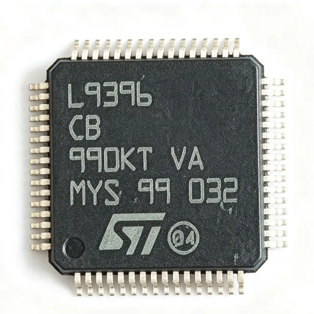
L9396L - Automotive Quad Low-Side Driver | STMicroelectronics
The L9396L is a quad low-side driver IC from STMicroelectronics, designed for automotive and industrial applications requiring robust, high-current switching of inductive or resistive loads. It integrates four independent low-side power outputs with built-in protection features, making it suitable for driving relays, solenoids, LEDs, and small motors. The device operates over a wide supply voltage range and is housed in a compact surface-mount package, enabling space-efficient PCB designs. A low-side driver is a type of power switch that connects the load to ground when activated, with the load connected between the positive supply and the driver output. This configuration is common in automotive body control modules, where multiple loads such as lamps, valves, and actuators must be switched reliably. Low-side drivers are preferred for their simplicity and ease of driving with standard logic-level signals, and they form a key building block in power management and load control systems. Key features of the L9396L include four high-current outputs, each capable of sourcing significant current to drive a variety of loads. The device incorporates overcurrent protection, thermal shutdown, and overvoltage clamping to safeguard both the IC and the connected loads. Its logic inputs are compatible with 3.3V and 5V microcontrollers, simplifying integration with modern automotive ECUs. The wide operating temperature range of -40°C to +150°C ensures reliable performance in harsh under-hood environments. Technically, the L9396L uses a robust bipolar/CMOS/DMOS (BCD) process technology, which combines low on-resistance power transistors with precise analog control circuitry. This architecture minimizes power dissipation and ensures fast switching times, reducing electromagnetic interference (EMI) in automotive networks. The device also features a serial peripheral interface (SPI) for advanced diagnostics and control, allowing the microcontroller to read fault status and configure output behavior, which is critical for safety-critical applications. Typical applications include automotive body control modules, where the L9396L drives exterior and interior lighting, relays for power windows and door locks, and solenoid valves in transmission or braking systems. It is also used in industrial automation for controlling actuators and in smart power distribution units. The device's ability to handle inductive loads with built-in freewheeling protection makes it ideal for relay and solenoid driving without external clamping diodes. When designing with the L9396L, ensure adequate PCB copper area for heat dissipation, especially when driving multiple outputs at high current simultaneously. The SPI interface requires proper pull-up resistors and careful layout to maintain signal integrity. Additionally, the supply voltage must be decoupled with a suitable capacitor close to the VCC pin to handle transient currents during switching.
L9678-TR - Automotive Airbag System IC | STMicroelectronics
The L9678-TR is a highly integrated automotive airbag system IC from STMicroelectronics, designed for safety-critical restraint systems. It combines a high-voltage squib driver, a 3.3V/5V voltage regulator, and a PSI5 interface in a single package, enabling compact and reliable airbag control unit designs. The device operates over a wide supply voltage range and is qualified to AEC-Q100 for automotive applications. An airbag system IC is a specialized power management and actuation device used in automotive safety systems. It integrates the high-voltage drivers that fire the squib (the initiator that inflates the airbag), along with the power supply regulation and communication interfaces needed to coordinate with the central airbag control unit. This integration reduces component count, PCB area, and system cost while improving reliability. Key features of the L9678-TR include a high-voltage squib driver capable of delivering the required firing current, an integrated voltage regulator providing stable 3.3V or 5V output for the microcontroller and sensors, and a PSI5 interface for connecting peripheral satellite sensors. The device also includes comprehensive diagnostic and protection features, such as overcurrent, overvoltage, and thermal shutdown, ensuring safe operation in harsh automotive environments. The L9678-TR is built on STMicroelectronics' robust automotive process technology, ensuring high reliability and long-term availability. Its architecture supports both driver and passenger airbag configurations, as well as side and curtain airbags, making it a versatile solution for modern vehicle safety systems. The device is available in a compact package suitable for surface-mount assembly, and its pinout is optimized for efficient PCB layout. Typical applications include driver and passenger airbag control units, side and curtain airbag systems, and seatbelt pretensioner systems. The L9678-TR is also suitable for other pyrotechnic actuation applications, such as battery disconnect switches in electric vehicles. Its integrated PSI5 interface simplifies the connection of satellite sensors, reducing wiring complexity and improving system reliability. When designing with the L9678-TR, it is essential to follow the manufacturer's guidelines for PCB layout, especially regarding the high-voltage squib driver traces and the thermal management of the integrated regulator. Proper decoupling and filtering of the power supply are critical to ensure stable operation and to meet electromagnetic compatibility (EMC) requirements. The device's diagnostic features should be utilized to implement robust fault detection and reporting in the system software.

L9678P - Automotive Airbag System Basis IC | STMicroelectronics (Tape & Reel)
The STMicroelectronics L9678P is an automotive user-configurable airbag system basis IC (SBI) integrating a 4-channel satellite sensor interface, dual linear regulators, PSI5 remote sensor support, and a battery cut-off switch in a 64-pin LQFP package. According to the STMicroelectronics datasheet, the device operates across an automotive battery range of 6 V to 18 V (with load-dump tolerance up to 40 V), targets emerging market airbag platforms, and pairs with the SPC560Px microcontroller and an on-board acceleration sensor or PSI5 sensor to form a complete airbag electronic control unit. An airbag system basis IC is a mixed-signal power management and sensor interface device that consolidates the discrete components historically required around an automotive airbag ECU: protected battery feed, energy reserve capacitor management, sensor interface (analog or PSI5), squib drivers, and microcontroller supply rails. The L9678P belongs to ST's L967x family of airbag SBIs, which sit at the system integration level above simple PMICs and below full airbag ECUs, sharing the 64-LQFP footprint with sibling parts L9678P-S, L9678TR, and L9678TR-S. Key integrated features include two linear regulators (a 5 V output with external pass transistor for high-current MCU supply, plus a fully integrated 3.3 V output), an optional 7.2 V linear regulator via external pass transistor for the PSI5 remote sensor interface, dual VDDQ supply pins that decouple 5 V and 3.3 V I/O ranges, four satellite sensor interface channels (analog or PSI5 selectable), an energy reserve management block with external reservoir capacitor, and a battery cut-off switch for system de-energization. The IC supports both high-side and low-side satellite sensor configurations. Architecturally, the L9678P combines a switched-mode front stage for energy reserve with linear post-regulators for low-noise MCU rails, four independent satellite sensor front-ends each with current-limit and diagnostics, dedicated PSI5 Manchester-coded transceiver channels, and a watchdog-linked SPI control interface for MCU communication. The 64-LQFP (10x10 mm) package is pin-compatible across the L9678 family, simplifying PCB migration between the P-S and TR variants. Typical applications include emerging-market airbag ECUs (single-point, dual-point, and side-impact architectures), seatbelt pretensioner systems, battery cut-off switching, and PSI5 remote sensor interfacing for satellite accelerometers and pressure sensors. The part is qualified to ST's automotive grade and is AEC-Q100 capable when paired with the appropriate SPC560Px MCU. When designing with the L9678P, ensure the energy reserve capacitor is sized per the ST application note for the target deployment time (typically 470 µF to 2200 µF electrolytic), the VDDQ pin is bonded to the appropriate I/O voltage, and a proper heatsinking or copper-pour footprint is used on the LQFP thermal pad area. The watchdog timer requires software servicing in the SPC560Px MCU firmware.
L9678PTR - Automotive Airbag System Basis IC | STMicroelectronics
The STMicroelectronics L9678PTR is an automotive user-configurable airbag system basis IC (SBI) integrating a 4-channel satellite sensor interface, dual linear regulators, PSI5 remote sensor support, and a battery cut-off switch in a 64-pin LQFP package. According to the STMicroelectronics datasheet, the device operates across an automotive battery range of 6 V to 18 V (with load-dump tolerance up to 40 V), targets emerging market airbag platforms, and pairs with the SPC560Px microcontroller and an on-board acceleration sensor or PSI5 sensor to form a complete airbag electronic control unit. An airbag system basis IC is a mixed-signal power management and sensor interface device that consolidates the discrete components historically required around an automotive airbag ECU: protected battery feed, energy reserve capacitor management, sensor interface (analog or PSI5), squib drivers, and microcontroller supply rails. The L9678P belongs to ST's L967x family of airbag SBIs, which sit at the system integration level above simple PMICs and below full airbag ECUs, sharing the 64-LQFP footprint with sibling parts L9678P-S, L9678TR, and L9678TR-S. Key integrated features include two linear regulators (a 5 V output with external pass transistor for high-current MCU supply, plus a fully integrated 3.3 V output), an optional 7.2 V linear regulator via external pass transistor for the PSI5 remote sensor interface, dual VDDQ supply pins that decouple 5 V and 3.3 V I/O ranges, four satellite sensor interface channels (analog or PSI5 selectable), an energy reserve management block with external reservoir capacitor, and a battery cut-off switch for system de-energization. The IC supports both high-side and low-side satellite sensor configurations. Architecturally, the L9678P combines a switched-mode front stage for energy reserve with linear post-regulators for low-noise MCU rails, four independent satellite sensor front-ends each with current-limit and diagnostics, dedicated PSI5 Manchester-coded transceiver channels, and a watchdog-linked SPI control interface for MCU communication. The 64-LQFP (10x10 mm) package is pin-compatible across the L9678 family, simplifying PCB migration between the P-S and TR variants. Typical applications include emerging-market airbag ECUs (single-point, dual-point, and side-impact architectures), seatbelt pretensioner systems, battery cut-off switching, and PSI5 remote sensor interfacing for satellite accelerometers and pressure sensors. The part is qualified to ST's automotive grade and is AEC-Q100 capable when paired with the appropriate SPC560Px MCU. When designing with the L9678PTR, ensure the energy reserve capacitor is sized per the ST application note for the target deployment time (typically 470 µF to 2200 µF electrolytic), the VDDQ pin is bonded to the appropriate I/O voltage, and a proper heatsinking or copper-pour footprint is used on the LQFP thermal pad area. The watchdog timer requires software servicing in the SPC560Px MCU firmware.
L9678PTR-S - Automotive Airbag SBC w/ PSI5 & Battery Cut-Off | ST
The STMicroelectronics L9678PTR-S is an automotive-grade System Basis Chip (SBC) for emerging-market airbag applications, integrating a configurable airbag driver, a battery cut-off switch, and a PSI5 remote sensor interface in a single 64-pin LQFP (10x10 mm) package. Headline parameters: operating voltage range 6 V to 18 V (load-dump tolerant up to 40 V), integrated ARM-based microcontroller for deployment logic, and dual PSI5 channels for satellite sensor communication. An SBC (System Basis Chip) is a category of automotive power + communication IC that consolidates the voltage regulators, communication transceivers (CAN/LIN/PSI5/SPI), watchdog, and diagnostic features needed by an ECU on a single die. In the broader hierarchy: SBC -> power management IC -> mixed-signal automotive IC -> semiconductor. Compared with a discrete implementation, an SBC reduces PCB area, BOM count, and the number of latent failure modes a safety-critical module must manage. Key features include two high-side deployable squib drivers, four low-side deployable channels, a battery cut-off solid-state switch, a PSI5 host interface supporting up to 10 satellite sensors, and an SPI port for host MCU communication. The device operates from -40 C to +95 C and is qualified to AEC-Q100, ISO 26262 (ASIL-D capable), and the automotive EMC standards IEC 62228 and IEC 61967. Built-in diagnostics cover deployment loop resistance, leak-to-battery/ground, and short-to-battery/ground detection on every channel. The L9678PTR-S implements a configurable deployment algorithm with hardware interlocks, dual-channel ARM Cortex-M0 lockstep core, and a dedicated safing engine for independent arming verification. The on-chip DC-DC pre-regulator supplies an internal 5 V / 3.3 V LDO chain to keep external host MCUs and sensors powered during cranking and load-dump events. Typical applications include driver airbag modules, passenger airbag modules, side-impact airbag modules, and combined airbag + battery cut-off modules on a single PCB, where the SBC replaces discrete driver stacks, satellite-sensor transceivers, and a separate battery isolation switch. Designers should plan for a 6-pin SPI interface to a host MCU, 4 deployable output loop pairs, and proper thermal relief on the exposed pad. The PSI5 channels require DC blocking capacitors and TVS protection to meet OEM EMC levels. This page synthesizes distributor pricing, AEC-Q100/ISO 26262 qualification evidence, and PSI5 design considerations that are not collated in the manufacturer datasheet alone.
L9678TR - Automotive SBC for Airbag Systems | STMicroelectronics
The STMicroelectronics L9678TR is an automotive-grade System Basis Chip (SBC) designed for airbag and passive-safety applications, integrating a 5V/3.3V selectable LDO voltage regulator, a watchdog timer, and a SPI-controlled diagnostic interface in a 64-pin LQFP (10x10 mm) package. It operates from a 6V to 35V supply rail and supports -40C to +95C ambient operation, making it qualified for under-the-hood automotive deployment. A System Basis Chip (SBC) is a category of mixed-signal power management IC that consolidates multiple discrete functions - typically a buck/linear regulator, watchdog, communication transceiver, and sensor diagnostics - into a single silicon die. The SBC sits hierarchically below the main microcontroller in an automotive ECU, providing both power conversion and safety monitoring. L9678TR is purpose-built for occupant-safety modules such as airbag ECUs and seatbelt pretensioners, where ASIL-B functional safety classification and continuous diagnostic coverage are mandatory. Key features include a high-efficiency 5V/3.3V LDO with integrated power-good signal, a programmable windowed watchdog with selectable timeout, dual squib drivers with on-chip current limiting, and SPI communication at up to 5 MHz for configuration and fault readback. The device also integrates a sensor-supply output, arming logic, and a high-side driver for warning lamp control. A typical application circuit uses the L9678TR as the single supply and safety island for an airbag control unit (ACU) hosting an SPC56 or SPC58 automotive MCU. From an architectural perspective, the L9678TR uses a BCD (Bipolar-CMOS-DMOS) process that allows the 35V-tolerant power paths and the squib-driver high-current outputs to coexist with the low-voltage CMOS control logic on a single die. Each squib driver includes programmable diagnostic current sources and a charge-pump-driven FET gate drive that maintains safe operation even when the supply dips to 6V during crank conditions. Typical applications are automotive airbag control units, seatbelt pretensioner modules, and other restraint-system ECUs requiring ASIL-B/D diagnostics. The wide 6V-35V input range also makes the part suitable for industrial 24V safety systems. When designing with the L9678TR, the LDO output capacitor must use a low-ESR ceramic of at least 4.7 uF to maintain loop stability across the -40C to +95C range, and the watchdog timer window must be configured to match the host MCU's service period. This page synthesizes distributor pricing, drop-in same-family alternatives, and design notes not found in the manufacturer datasheet.
L9678TR-S - User-Configurable Airbag IC | STMicroelectronics
STMicroelectronics L9678TR-S is a user-configurable airbag interface integrated circuit for automotive restraint systems, provided in a 64-pin LQFP package and associated with the AEC-Q100 automotive qualification series. The device combines the airbag safing, deployment, and diagnostic functions required by vehicle occupant-restraint electronic-control systems into one automotive专用 interface IC. It is offered in tray packaging under the L9678TR-S ordering code and is described by STMicroelectronics as a product in full production. An airbag interface IC is a specialized form of automotive power-management and interface semiconductor. It sits between a vehicle's restraint-control electronics and the airbag deployment circuits, helping translate control commands into protected deployment actions while coordinating fault detection, safing, and diagnostic functions. Within the product hierarchy, the L9678TR-S is a dedicated airbag IC, a specialized interface IC, an automotive analog and power IC, and ultimately a semiconductor. The principal verified characteristics are its user-configurable airbag functionality, 64-pin LQFP construction, automotive AEC-Q100 series association, and availability in a tray package. Its 64-pin package provides the mixed-signal and power connections required for a complex automotive restraint interface. Exact electrical ratings, internal-channel counts, diagnostic coverage, timing limits, and protection thresholds were not included in the supplied search extract and therefore must be confirmed against the manufacturer datasheet before schematic capture or safety validation. The L9678TR-S is based on the STMicroelectronics L9678 user-configurable airbag IC family documented in the manufacturer datasheet identified as DocID025869 Rev 3. The related L9678P family provides a pin-compatible product option referenced by STMicroelectronics, with dedicated supply arrangements and an optional 7.2 V linear-regulation path described for the related device. Designers should not transfer those L9678P-specific details to L9678TR-S without checking the applicable datasheet. Typical uses include automotive airbag control units, seat-belt pretensioner controllers, vehicle occupant-restraint modules, frontal-impact sensing systems, and side-impact restraint controllers. The part is most appropriate when an OEM or Tier 1 requires an automotive-qualified, configurable deployment interface rather than a generic logic or power component. For a new design, validate every external resistor, capacitor, squib-driver interface, diagnostic threshold, and fault-response setting against the released STMicroelectronics datasheet. PCB placement must preserve the package's thermal and high-current land pattern, while production programming and end-of-line test should follow STMicroelectronics' documented configuration procedure. This product page combines verified package, function, lifecycle, automotive-qualification, pricing, and source information with explicit data-gap markers and same-brand pin-compatible alternatives. It adds practical sourcing and design context without inventing unpublished electrical limits or safety-performance claims.