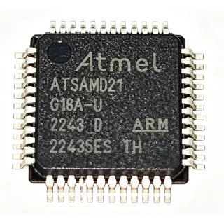
DSPIC33CH512MP505-I/PT - 100MHz Dual-Core 16-bit DSC, 512KB Flash, 48-TQFP | Microchip
MPN: DSPIC33CH512MP505-I/PT ✓ Hoạt độngDSPIC33CH512MP505-I/PT Tóm tắt
A Digital Signal Controller (DSC) sits at the intersection of a microcontroller (MCU) and a Digital Signal Processor (DSP). The MCU side provides deterministic interrupt handling, peripherals (UART, SPI, I2C, CAN, PWM), and general-purpose I/O; the DSP side adds single-cycle MAC, saturating arithmetic, and zero-overhead looping. In the dsPIC33CH hierarchy, this places the device within: DSC -> dsPIC33 family -> dsPIC33CH sub-family (dual-core) -> motor-control and digital-power class. This dual-class positioning explains why the part is marketed for both motor-control firmware and high-frequency switching power conversion.
Key features include: dual 16-bit DSC cores running up to 100 MIPS (main) and 90 MIPS (secondary), each with its own DSP engine; 512 KB on-chip Flash with live update support; up to 96 KB total RAM (including a dedicated slave-core partition); high-resolution 7.5 ns PWM with multiple fault inputs; integrated CAN FD controller; and rich analog (high-speed ADC, comparators, DAC). The dual-core architecture allows closed-loop control math on one core while the second core handles housekeeping, communication stacks, or a second motor-control loop.
Typical applications span field-oriented control (FOC) of PMSM/BLDC motors, sensorless motor drives, multi-axis servo systems, on-board chargers (OBC), DC-DC converters, photovoltaic inverters, and digital LED lighting. The high-resolution PWM and fast ADC sample timing enable switching frequencies beyond 1 MHz with sub-percent duty-cycle accuracy, while the secondary core can be dedicated to housekeeping, safety monitoring, or a CAN FD communication stack.
Design consideration: ensure that the main and secondary core pin-ownership tables (set in firmware) match the board's pin map before bringing the secondary core out of reset, and place decoupling capacitors (100 nF + bulk) within 5 mm of each VDD/VSS pin pair. The 48-TQFP package has limited thermal headroom - estimate the dissipation from the core clock and peripheral activity, then verify against the 31 C/W theta_JA on a 4-layer JEDEC board.
This page synthesizes distributor pricing, cross-reference alternatives from the dsPIC33CH family, and practical dual-core firmware design notes that are not aggregated in any single manufacturer datasheet.
Bộ thay thế dễ dàng lắp đặt cho DSPIC33CH512MP505-I/PT — cùng gói, chân-to-chân tương thích. Các bộ phận yêu cầu hàn PCB bị loại trừ.
Các biến thể trong loạt này
Các mẫu cùng loạt có thể lắp đặt dễ dàng tương thích với DSPIC33CH512MP505-I/PT (cùng hình factor và footprint) — khác nhau ở Package, Slave Core Speed, ADC, High-Resolution PWM, Main Core Speed.
DSPIC33CH256MP506-I/PT
✅ Drop-In📋 Tham chiếu thay thế (không có trong danh mục)
DSPIC33CH512MP508-I/PT
✅ Drop-InLiên hệ để biết giá
Xem tài liệu →DSPIC33CH512MP505-E/PT
✅ Drop-InLiên hệ để biết giá
Xem tài liệu →DSPIC33CH512MP506-I/PT
✅ Drop-In ⚠️ Thông số chưa được xác minhLiên hệ để biết giá
Xem tài liệu →DSPIC33CH256MP508-I/PT
✅ Drop-In ⚠️ Thông số chưa được xác minhLiên hệ để biết giá
Xem tài liệu →DSPIC33CH256MP506T-I/PT
✅ Drop-In ⚠️ Thông số chưa được xác minhLiên hệ để biết giá
Xem tài liệu →DSPIC33CH512MP505-H/PT
✅ Drop-In📋 Tham chiếu thay thế (không có trong danh mục)
DSPIC33CH512MP505-I/PT Tỷ lệ tối đa & tính chất điện
| Family | dsPIC33CH (dual-core 16-bit DSC) |
| Main Core Speed | 100 MIPS (max) |
| Secondary Core Speed | 90 MIPS (max) |
| Program Memory (Flash) | 512 KB |
| Total RAM | Up to 96 KB (with dedicated slave partition) |
| Hộp | 48-pin TQFP (7x7 mm) |
| Operating Voltage | 3.0 V to 3.6 V |
| PWM Resolution | 7.5 ns (high-resolution) |
| CAN | CAN FD |
| Nhiệt độ hoạt động | -40 C to +85 C (Industrial, -I suffix) |
| Kiểu lắp đặt | Surface Mount |
| Cấp MSL | 3 (per JEDEC J-STD-020) |
| Lead-Free / RoHS | Yes (compliant) |
| DSP Engine | Yes (single-cycle MAC, dual 40-bit accumulators) |
| Debug Interface | ICSP / JTAG (multiple PGECx/PGEDx pairs) |
Cấu hình chân DSPIC33CH512MP505-I/PT
| Chân 1 | OSCI/OSCO — Main oscillator input/output (crystal or external clock) |
| Chân 2 | MCLR — Master Clear (reset) - active low |
| Chân 3 | PGECx — ICSP programming/debug clock (multiple pairs available) |
| Chân 4 | PGEDx — ICSP programming/debug data (multiple pairs available) |
| Chân 5 | VDD — 3.3 V core/supply voltage |
| Chân 6 | VSS — Ground |
| Chân 7 | ANx/VDDCORE — Analog input / regulated core voltage (refer to datasheet) |
| Chân 8 | PWM1H — PWM output (high-side), 7.5 ns resolution |
| Chân 9 | PWM1L — PWM output (low-side), 7.5 ns resolution |
| Chân 10 | PWM2H — PWM output (high-side) |
| Chân 11 | PWM2L — PWM output (low-side) |
| Chân 12 | PWM3H — PWM output (high-side) |
| Chân 13 | PWM3L — PWM output (low-side) |
| Chân 14 | PWM4H — PWM output (high-side) |
| Chân 15 | PWM4L — PWM output (low-side) |
| Chân 16 | FLTx — PWM fault input(s) (multiple) |
| Chân 17 | C1TX — CAN FD transmit |
| Chân 18 | C1RX — CAN FD receive |
| Chân 19 | U1TX — UART 1 transmit |
| Chân 20 | U1RX — UART 1 receive |
| Chân 21 | SCK1 — SPI 1 clock |
| Chân 22 | SDI1 — SPI 1 data in |
| Chân 23 | SDO1 — SPI 1 data out |
| Chân 24 | SDA1 — I2C 1 data |
| Chân 25 | SCL1 — I2C 1 clock |
| Chân 26 | AN0 — Analog input / GPIO |
| Chân 27 | AN1 — Analog input / GPIO |
| Chân 28 | AN2 — Analog input / GPIO |
| Chân 29 | AN3 — Analog input / GPIO |
| Chân 30 | AN4 — Analog input / GPIO |
| Chân 31 | AN5 — Analog input / GPIO |
| Chân 32 | AN6 — Analog input / GPIO |
| Chân 33 | AN7 — Analog input / GPIO |
| Chân 34 | AN8 — Analog input / GPIO |
| Chân 35 | AN9 — Analog input / GPIO |
| Chân 36 | VCAP — Core voltage decoupling capacitor |
| Chân 37 | VDD — 3.3 V supply |
| Chân 38 | VSS — Ground |
| Chân 39 | INT0 — External interrupt 0 / GPIO |
| Chân 40 | T2CK — Timer2 clock / GPIO |
| Chân 41 | OC1 — Output compare 1 / GPIO |
| Chân 42 | RPI/RPO — Remappable I/O - configurable peripheral pin |
| Chân 43 | RPI/RPO — Remappable I/O - configurable peripheral pin |
| Chân 44 | RPI/RPO — Remappable I/O - configurable peripheral pin |
| Chân 45 | RPI/RPO — Remappable I/O - configurable peripheral pin |
| Chân 46 | RPI/RPO — Remappable I/O - configurable peripheral pin |
| Chân 47 | AVDD — Analog supply voltage (3.3 V) |
| Chân 48 | AVSS — Analog ground |
Ứng dụng tiêu biểu
DSPIC33CH512MP505-I/PT phù hợp cho 6 Áp dụngs: Field-Oriented Control (FOC) of PMSM / BLDC Motors, Digital Switch-Mode Power Supplies (SMPS) and DC-DC Converters, On-Board Chargers (OBC) for Electric Vehicles, Photovoltaic (PV) Inverters and Solar Power Optimizers, Industrial Servo and Robotics Multi-Axis Controllers, Digital LED Lighting and Architectural Dimming.
Field-Oriented Control (FOC) of PMSM / BLDC Motors
The DSPIC33CH512MP505-I/PT is engineered for field-oriented control of permanent-magnet synchronous and brushless DC motors in industrial drives and appliances. Its dual 16-bit DSC cores running at 100 MIPS (main) and 90 MIPS (secondary) can execute a full FOC algorithm - Clarke/Park transforms, space-vector modulation, and a PI speed/current loop - in microsecond-scale update rates while the secondary core handles a CAN FD comm stack or a second motor channel. The high-resolution 7.5 ns PWM with dead-time control and programmable fault inputs is critical for switching above 20 kHz with sub-1% duty-cycle accuracy, which directly improves torque ripple and acoustic behavior. Recommended companion parts include Microchip MCP8026 3-phase gate drivers, LIN/CAN FD transceivers like MCP2562FD, and Hall/encoder interface ICs from the dsPIC ecosystem.
Được đề xuất
Digital Switch-Mode Power Supplies (SMPS) and DC-DC Converters
The DSPIC33CH512MP505-I/PT fits isolated and non-isolated DC-DC converters, LLC resonant converters, and totem-pole PFC stages where deterministic digital control replaces analog compensation. The high-resolution 7.5 ns PWM enables multi-hundred-kHz switching with tight duty-cycle control, while the high-speed ADC sampling aligned to the PWM allows cycle-by-cycle current-mode control with sub-microsecond latency. The dual-core topology lets one core run voltage/current loops at fixed frequency while the second core handles housekeeping, telemetry, or PMBus/SMBus communication. The 512 KB Flash accommodates full state-machine and adaptive-control firmware without resorting to external memory. Recommended companions: digital isolators (Microchip dsPIC ecosystem), gate drivers (MCP14628), and current-sense amplifiers.
Được đề xuất
On-Board Chargers (OBC) for Electric Vehicles
The DSPIC33CH512MP505-I/PT is well-suited for on-board charger (OBC) and auxiliary DC-DC converter stages in mild-hybrid and full-electric vehicles where ISO 26262 functional safety and a CAN FD vehicle network are mandatory. The dual-core architecture supports a primary core running PFC + LLC control at fixed switching frequency, while the secondary core executes a CAN FD stack and periodic self-test diagnostics to support ASIL-class safety requirements. With 512 KB Flash and up to 96 KB RAM, designers can integrate full state machines, soft-start profiles, and adaptive charging algorithms (CC/CV) without external memory. Recommended companions: isolated gate drivers, isolated CAN FD transceivers, and high-voltage op-amps for current sensing.
Được đề xuất
Photovoltaic (PV) Inverters and Solar Power Optimizers
The DSPIC33CH512MP505-I/PT's combination of high-resolution PWM, dual-core topology, and CAN FD makes it a strong fit for residential and small-commercial photovoltaic inverters and module-level power optimizers. The main core can run MPPT and grid-synchronization algorithms while the secondary core handles inverter control loops or a second tracker channel, reducing BOM and PCB complexity. The high-speed ADC sampling aligned to the PWM provides accurate grid-current sensing at zero-crossing, which is critical for low-distortion grid-tie operation. With 512 KB Flash and industrial -40 C to +85 C operation, the device supports the firmware density and field-environment reliability required by PV installations. Recommended companions: isolated CAN FD transceivers, current-sense amplifiers, and gate drivers for IGBT/MOSFET bridge legs.
Được đề xuất
Industrial Servo and Robotics Multi-Axis Controllers
The DSPIC33CH512MP505-I/PT targets multi-axis servo controllers used in robotics, CNC machinery, and AGVs, where deterministic closed-loop control on multiple axes must coexist with a fast CAN FD command interface. The dual-core layout allows a separate control loop per axis with shared housekeeping handled by the secondary core, while the high-resolution PWM and high-speed ADC pairings maintain precise current-loop timing per axis at 20-50 kHz switching rates. The 512 KB Flash supports field-orientation control code, autotuning tables, and trajectory profiles for several axes. Recommended companions: digital isolators, RS-422/RS-485 transceivers for legacy servo interfaces, and CAN FD transceivers for inter-axis coordination.
Được đề xuất
Digital LED Lighting and Architectural Dimming
The DSPIC33CH512MP505-I/PT's high-resolution PWM (7.5 ns) and high-speed ADC are well-matched to digital LED drivers where per-channel dimming depth and color-mixing precision determine lighting quality. The main core can run multi-channel PWM mixing for RGBW fixtures while the secondary core handles DMX/RDM or DALI-2 communication, eliminating the need for an extra communication microcontroller. The 512 KB Flash allows rich lighting-effect libraries to be embedded on-device. With industrial temperature rating, the device supports professional architectural and stage-lighting fixtures. Recommended companions: DALI-2/DMX transceivers, high-current LED driver ICs, and isolated CAN FD for show-control networks.
Được đề xuất
Tóm tắt các sản phẩm được đề xuất
Dữ liệu tham khảo kỹ thuật cho DSPIC33CH512MP505-I/PT — so sánh, hướng dẫn thiết kế và thông tin tuân thủ.
Hướng dẫn chọn lựa
So sánh với các sản phẩm thay thế
| Tham số | Sản phẩm này | DSPIC33CH256MP506-I/PT | DSPIC33CH512MP508-I/PT | DSPIC33CH512MP505-E/PT | DSPIC33CH512MP505-H/PT |
|---|---|---|---|---|---|
| Brand | Microchip Technology | Microchip Technology | Microchip Technology | Microchip Technology | Microchip Technology |
| Package | 48-TQFP (7x7) | 48-TQFP (7x7) - same | 48-TQFP (7x7) - same | 48-TQFP (7x7) - same | 48-TQFP (7x7) - same |
| Flash Memory | 512 KB | 256 KB | 512 KB | 512 KB | 512 KB |
| Main Core Speed | 100 MIPS | 100 MIPS | 100 MIPS | 100 MIPS | 100 MIPS |
| Secondary Core Speed | 90 MIPS | 90 MIPS | 90 MIPS | 90 MIPS | 90 MIPS |
| CAN FD | Yes | Yes | Yes | Yes | Yes |
| PWM Resolution | 7.5 ns (high-resolution) | 7.5 ns | 7.5 ns | 7.5 ns | 7.5 ns |
| Temperature Grade | -40 C to +85 C (Industrial) | -40 C to +85 C (Industrial) | -40 C to +85 C (Industrial) | -40 C to +125 C (Extended) | High-temp grade (refer to datasheet) |
Bảo phân biệt quan trọng
- Dual-core topology with live update (vsDSPIC33EP512MU810-I/PT)
- High-resolution 7.5 ns PWM with integrated CAN FD (vsDSPIC33CH256MP506-I/PT)
- Industrial temperature grade as standard (vsDSPIC33CH512MP505-E/PT)
Ghi chú thiết kế
Estimated: at 3.3 V VDD with both cores active, 100 MHz main + 90 MHz secondary, plus PWM and ADC, the device draws roughly 60-90 mA - place a 100 nF X7R ceramic within 5 mm of each VDD/VSS pin pair and a 10 uF bulk capacitor on the AVDD/AVSS analog supply. The on-chip voltage regulator (VCAP pin) requires an external low-ESR ceramic (typically 4.7 uF) for core stability; do not use the VCAP node to power external loads.
Pin-ownership on the dsPIC33CH family is configurable in firmware - the main core owns each I/O pin by default; the secondary core must explicitly request ownership through the PPS (Peripheral Pin Select) and pin-ownership registers before driving any output. Verify the ownership tables match the PCB schematic before bringing the secondary core out of reset. Multiple PGECx/PGEDx pairs are available for ICSP - choose the pair that is unrouted on your board to keep programming accessible without rework.
Estimated: at full dual-core 190 MIPS aggregate throughput on a 4-layer JEDEC board, the 48-TQFP package (theta_JA approximately 31 C/W) will rise 5-10 C above ambient - well within industrial limits. At extended temperature operation above 100 C junction, derate by 1 mA / C per the package thermal curves and verify with an in-system sensor.
Do not assume that the secondary core is initialized automatically - it must be loaded with its own firmware image (live update Flash partition) and released from reset by the main core. Live update requires both firmware images to be linked with the correct addresses and a documented dual-image boot protocol; review the dsPIC33CH Family User Guide before designing live-update hardware. CAN FD configuration must match the bus bit timing - mismatched CAN FD bit rates are a common cause of bus-off states on multi-node networks.
Thông tin tuân thủ
RoHS compliant per Microchip product page and distributor listings as of 2026-09-22. AEC-Q100 qualification status not confirmed in verified web data - [DATA_NEEDED]. Halogen-free status not stated in verified data - [DATA_NEEDED].