GP2Y+ - 2-Way MMIC Power Splitter 1.6-3.3 GHz | Mini-Circuits
MPN: GP2Y+ ✓ Hoạt độngGP2Y+ Tóm tắt
A power splitter/combiner is a passive RF component that divides an input signal into two equal-amplitude outputs (splitter mode) or combines two inputs into a single output (combiner mode). It belongs to the broader category of RF power dividers within signal conditioning components, used in wireless infrastructure, test instrumentation, and phased-array systems. The 2-way topology (one input, two outputs) makes it the most common building block in distribution networks where signal coherence and amplitude balance matter.
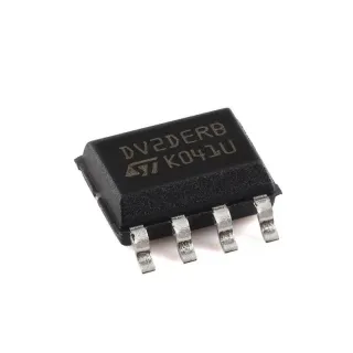
The GP2Y+ uses Mini-Circuits' proprietary GaAs MMIC process with on-chip resistors for the resistive-divider network, which provides inherently broadband behavior across the 1600-3300 MHz band. The exposed-pad 12-VQFN package (DQ1225) yields a low thermal-resistance path and a compact 3x3 mm footprint suitable for high-density PCB designs. Internal dissipation handling and wideband phase tracking support multi-section use cases such as corporate-feed networks in antenna arrays.
Typical applications include LTE/4G and 5G sub-6 GHz infrastructure, in-building DAS (distributed antenna systems), Wi-Fi 2.4 GHz band signal sampling, RFID reader splitting networks, and RF test equipment where repeatable signal division with low loss is required. Its small size and zero-bias operation make it especially attractive for compact module designs.
When designing with the GP2Y+, follow the recommended PCB layout (PL-282) on Rogers RO4350B dielectric with continuous bottom-side ground. Maintain 50 ohm trace impedance from input to the splitter junction and from each output port; insufficient trace width degrades VSWR and worsens amplitude balance. Avoid routing DC or digital signals near the RF traces to prevent coupling.
Bộ thay thế dễ dàng lắp đặt cho GP2Y+ — cùng gói, chân-to-chân tương thích. Các bộ phận yêu cầu hàn PCB bị loại trừ.
Các biến thể trong loạt này
Các mẫu cùng loạt có thể lắp đặt dễ dàng tương thích với GP2Y+ (cùng hình factor và footprint) — khác nhau ở Frequency Range, Package, RoHS Status, Function, Isolation.
GP2Y1+
✅ Drop-In ⚠️ Thông số chưa được xác minhLiên hệ để biết giá
Xem tài liệu →GP2S+
✅ Drop-In ⚠️ Thông số chưa được xác minhLiên hệ để biết giá
Xem tài liệu →GP2Y+ Thông số kỹ thuật (bản công bố của nhà sản xuất)
| Part Number | GP2Y+ |
| Manufacturer | Mini-Circuits |
| Chức năng | 2-Way MMIC Power Splitter/Combiner |
| Frequency Range | 1600 MHz to 3300 MHz |
| Impedance | 50 ohm |
| Number of Ways | 2 |
| Insertion Loss | 1.5 dB (typical, above 3 dB theoretical split) |
| Isolation | 17 dB minimum |
| VSWR | 1.2:1 typical |
| Amplitude/Phase Imbalance | 4 degrees maximum |
| Hộp | 12-VQFN Exposed Pad (Case Style DQ1225) |
| Kiểu lắp đặt | Surface Mount |
| Nhiệt độ hoạt động | -40C to +85C |
| Storage Temperature | -40C to +85C |
| Trạng thái RoHS | Compliant (note + suffix) |
| Technology | GaAs MMIC, passive (no DC bias required) |
Cấu hình chân GP2Y+
| Chân 1 | GND — Ground (tied to exposed pad) |
| Chân 2 | GND — Ground (tied to exposed pad) |
| Chân 3 | OUT1 — RF Output Port 1 |
| Chân 4 | GND — Ground (tied to exposed pad) |
| Chân 5 | OUT2 — RF Output Port 2 |
| Chân 6 | GND — Ground (tied to exposed pad) |
| Chân 7 | GND — Ground (tied to exposed pad) |
| Chân 8 | IN — RF Input Port |
| Chân 9 | GND — Ground (tied to exposed pad) |
| Chân 10 | GND — Ground (tied to exposed pad) |
| Chân 11 | NC — Not connected (per datasheet) |
| Chân 12 | GND — Ground (tied to exposed pad) |
| Chân EP | GND — Exposed thermal/ground pad (bottom) |
Đặc tính điện và nhiệt
| Nhiệt độ hoạt động | -40C to +85C |
| Nhiệt độ lưu trữ | -40C to +85C |
Các thông số điện và nhiệt của GP2Y+ được công bố bởi nhà sản xuất.
Ứng dụng tiêu biểu
GP2Y+ phù hợp cho 6 Áp dụngs: LTE / 4G Base-Station Distribution, 5G Sub-6 GHz Small-Cell / Femtocell, In-Building Distributed Antenna Systems (DAS), Wi-Fi 2.4 GHz / ISM Band Signal Sampling, RFID Reader Split/Combine Networks, RF Test & Measurement Equipment.
LTE / 4G Base-Station Distribution
The GP2Y+ fits LTE/4G base-station distribution networks because its 1600-3300 MHz band directly overlaps LTE bands 1, 2, 3, 4, 7, 10, 25, 38, 40, and 41. With 17 dB minimum isolation between output ports, the GP2Y+ prevents cross-talk between sectors or MIMO streams that share a common feed. Placed at the corporate-feed junction of a 2x2 or 4x4 MIMO radio, the 1.5 dB insertion loss adds less than 0.4 dB per branch to the link budget. As a passive GaAs MMIC it draws zero DC and survives -40C to +85C outdoor enclosure conditions.
Được đề xuất
5G Sub-6 GHz Small-Cell / Femtocell
The GP2Y+ supports 5G sub-6 GHz small-cell and femtocell radios because the 1600-3300 MHz range covers 5G NR bands n7, n38, n40, and n41. With a 12-VQFN exposed-pad (3x3 mm DQ1225) footprint, the GP2Y+ allows dense placement next to RFICs in compact small-cell modules. The 4 degree max amplitude/phase imbalance preserves beam-pointing accuracy in phased-array corporate-feed networks, and the 1.2:1 typical VSWR keeps mismatch loss below 0.1 dB at each split.
Được đề xuất
In-Building Distributed Antenna Systems (DAS)
The GP2Y+ suits in-building DAS head-end and remotes because it splits downlink signals to multiple radiating antennas or combines uplink signals from multiple antennas with 17 dB minimum port-to-port isolation. This isolation prevents antenna-to-antenna coupling that would otherwise create multipath fading or self-interference in the same RF chain. Its -40C to +85C industrial temperature rating handles unconditioned telecom closets, and the RoHS-compliant surface-mount DQ1225 case supports automated high-volume assembly.
Được đề xuất
Wi-Fi 2.4 GHz / ISM Band Signal Sampling
The GP2Y+ operates across the 2.4 GHz Wi-Fi / ISM band (2400-2483.5 MHz), sitting well inside its 1600-3300 MHz passband. Used as a tap/sampler, the 2-way topology allows a -10 dB or -20 dB resistive-divider tap to feed a monitor or spectrum-analyser port while the main path continues to the antenna - with only 1.5 dB insertion loss on the through path. The passive nature keeps cost low in high-volume consumer access points, and the small DQ1225 footprint fits next to the Wi-Fi FEM.
Được đề xuất
RFID Reader Split/Combine Networks
The GP2Y+ covers the 2.4 GHz and select sub-3 GHz RFID bands, supporting reader architectures that drive multiple antennas from a single transmitter. Placing the GP2Y+ at the corporate-feed point of two reader antennas gives 17 dB minimum isolation, so leakage from one antenna does not de-sense the other receiver channel. With 4 degree max phase imbalance, the GP2Y+ enables accurate time-of-arrival-based localisation, and GaAs MMIC passive operation suits battery-powered handheld readers.
Được đề xuất
RF Test & Measurement Equipment
The GP2Y+ is a good fit for RF test and measurement signal-conditioning modules such as signal-generator fan-outs, ATE test-head combiners, and switch-matrix distribution networks. Its 1.5 dB typical insertion loss is calibrated-out easily in vector-corrected test systems, while the 1.2:1 typical VSWR keeps measurement uncertainty low. The 12-VQFN exposed-pad case is friendly to ATE handler trays and pick-and-place assembly, and zero DC bias keeps the BOM small.
Được đề xuất
Tóm tắt các sản phẩm được đề xuất
Dữ liệu tham khảo kỹ thuật cho GP2Y+ — so sánh, hướng dẫn thiết kế và thông tin tuân thủ.
Hướng dẫn chọn lựa
So sánh với các sản phẩm thay thế
| Tham số | Sản phẩm này | GP2Y1+ | GP2S+ |
|---|---|---|---|
| Brand | Mini-Circuits | Mini-Circuits | Mini-Circuits |
| Package | 12-VQFN Exposed Pad (DQ1225) | 12-VQFN Exposed Pad (DQ1225) - same | 12-VQFN Exposed Pad (DQ1225) - same |
| Function | 2-Way MMIC Power Splitter/Combiner | 2-Way MMIC Power Splitter/Combiner | 2-Way MMIC Power Splitter/Combiner |
| Impedance | 50 ohm | 50 ohm | 50 ohm |
| DC Bias Required | No (passive) | No (passive) | No (passive) |
| RoHS | Compliant | Compliant | Compliant |
Bảo phân biệt quan trọng
- Broadband 1600-3300 MHz with single part number (vsNarrow-band 2-way splitters in 2.4 GHz ISM band only)
- Passive MMIC, zero DC bias (vsActive splitter variants requiring bias-tee and DC regulator)
- Compact 12-VQFN exposed-pad DQ1225 (vsLarger SOT-89 or connectorized splitter footprints)
Ghi chú thiết kế
Follow Mini-Circuits suggested PCB layout PL-282 for the GP2Y+: Rogers RO4350B dielectric 0.020 inch +/- 0.0015 inch, 1/2 oz copper each side, continuous bottom ground plane. Signal traces are not allowed inside the hatched keep-out region around the exposed pad. Other stack-ups may require trace-width/gap recalculation to keep 50 ohm impedance.
Place the GP2Y+ input port closest to the upstream amplifier or mixer to minimize common-mode coupling and trace loss. Maintain 50 ohm trace geometry on all three RF ports (IN, OUT1, OUT2); bend angles should be mitered and via-count minimized. Multiple GND vias around the exposed pad are required for thermal and RF grounding.
Do not route DC, digital, or noisy power traces under or beside the GP2Y+ RF traces - coupling can degrade isolation below the 17 dB minimum and induce amplitude imbalance. Verify the + suffix in the part number before ordering to ensure RoHS-compliant material set. Storage and operating temperature are both -40C to +85C per datasheet.
Estimated: GP2Y+ maximum internal dissipation is approximately 0.5 W typical for a resistive-divider splitter at full input power; with the DQ1225 exposed pad and proper bottom-side thermal via array, junction-temperature rise is well within the 85C operating limit at typical RF input levels of +20 dBm per port.
Thông tin tuân thủ
RoHS compliance confirmed by + suffix in part number per Mini-Circuits datasheet. REACH and conflict-mineral status not explicitly stated in the verified web data; refer to Mini-Circuits environmental compliance page for confirmation. Not AEC-Q100 qualified - GP2Y+ is not intended for automotive under-hood applications.