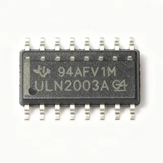
MC1413D - 7-Channel 50V Darlington Array | onsemi
MPN: MC1413D ✗ Cuối đờiMC1413D Tóm tắt
A bipolar transistor array is a group of discrete transistor functions integrated into one package. In this case, each output stage combines a high-gain Darlington transistor pair with an associated driver and clamp function. MC1413D belongs to the transistor-array hierarchy: NPN bipolar junction transistor, Darlington transistor array, transistor driver, discrete semiconductor, and surface-mount IC package.
The array provides seven independent output channels, each intended to accept a logic-level base signal and sink current from an externally supplied load supply. A 50 V collector-emitter rating supports applications involving higher load voltages than standard low-voltage logic arrays. The manufacturer datasheet identifies 500 mA peak inrush current as suitable for incandescent-lamp startup. It also states that internal suppression diodes help prevent problems associated with inductive loads.
Each Darlington stage sacrifices some voltage headroom compared with a single bipolar transistor because two emitter-base junctions appear in series in the drive path. That trade-off reduces required base current and simplifies interfacing, but the input and output voltage relationships must be checked against the application. Because the MC1413D is a current-sinking driver array, the load supply is normally connected to the common pins and each driven load returns to the corresponding output.
Typical uses include relay coils, solenoids, indicator lamps, printer mechanisms, small incandescent lamps, and other electromechanical loads. A designer should verify the continuous current, total package dissipation, inductive-load clamp behavior, and worst-case temperature for every channel rather than treating the 500 mA inrush figure as a continuous-current rating. Independent channel behavior also allows multiple loads to be switched from separate control logic.
For robust layouts, place the array close to the driven loads, provide a local return path for each load supply, and route high-current and high-dV/dt outputs away from sensitive control signals. Decoupling capacitors should be placed across the load-supply pins according to the wiring and load characteristics. The SOIC-16 package supports standard surface-mount assembly, but exposed copper and thermal planning remain important when several channels operate simultaneously at elevated current.
This product page consolidates the verified 50 V, 500 mA peak-inrush, seven-channel, and 16-pin SOIC information with practical load-driving guidance, sourcing links, a pinout reference, and a careful assessment of replacement options. Unlike a generic distributor listing, it distinguishes verified headline ratings from continuous-current and thermal parameters that still require datasheet-specific design confirmation.
Bộ thay thế dễ dàng lắp đặt cho MC1413D — cùng gói, chân-to-chân tương thích. Các bộ phận yêu cầu hàn PCB bị loại trừ.
MC1413B
✅ Drop-In📋 Tham chiếu thay thế (không có trong danh mục)
MC1413D Tỷ lệ tối đa & tính chất điện
| Transistor Array Configuration | 7 NPN Darlington channels |
| Collector-Emitter Breakdown Voltage | 50 V |
| Peak Inrush Current | 500 mA |
| Output Channel Count | 7 channels |
| Kiểu transitor | NPN Darlington bipolar transistor array |
| Hộp | 16-pin SOIC surface-mount package |
| Internal Suppression Diodes | Present |
| Primary Load Capability | 500 mA peak inrush |
Cấu hình chân MC1413D
| Chân 1 | GND — Ground connection |
| Chân 2 | IN1 — Input for output channel 1 |
| Chân 3 | OUT1 — Collector output for channel 1 |
| Chân 4 | IN2 — Input for output channel 2 |
| Chân 5 | OUT2 — Collector output for channel 2 |
| Chân 6 | IN3 — Input for output channel 3 |
| Chân 7 | OUT3 — Collector output for channel 3 |
| Chân 8 | GND — Ground connection |
| Chân 9 | COM — Common connection for internal suppression diodes |
| Chân 10 | OUT7 — Collector output for channel 7 |
| Chân 11 | IN7 — Input for output channel 7 |
| Chân 12 | OUT6 — Collector output for channel 6 |
| Chân 13 | IN6 — Input for output channel 6 |
| Chân 14 | OUT5 — Collector output for channel 5 |
| Chân 15 | IN5 — Input for output channel 5 |
| Chân 16 | COM — Common connection for internal suppression diodes |
Ứng dụng tiêu biểu
MC1413D phù hợp cho 6 Áp dụngs: Relay Coil Driver, Incandescent Lamp Driver, Printer Hammer Driver, Industrial Solenoid Interface, Consumer Appliance Control, Printer and Office Equipment.
Relay Coil Driver
MC1413D fits multi-relay control boards because its seven NPN Darlington channels can sink current from externally supplied coil circuits while the 50 V collector-emitter rating provides useful voltage headroom. Each channel reduces the control-logic drive burden compared with driving a single low-gain transistor directly. Internal suppression diodes help manage inductive kickback. Designers must still verify coil voltage, steady-state current, suppression energy, and thermal rise because the verified 500 mA value is a peak-inrush capability rather than a continuous-current guarantee.
Được đề xuất
Incandescent Lamp Driver
MC1413D is suitable for grouped incandescent indicators or machine lamps because the onsemi datasheet specifically identifies lamps as target loads and states that peak inrush currents up to 500 mA are permitted. The Darlington stages reduce required base-drive current, allowing seven lamp channels to be controlled from compatible logic without duplicating discrete driver circuitry. In continuous operation, engineers should calculate worst-case current, filament cold resistance, package dissipation, and channel-to-channel sharing instead of applying the 500 mA peak figure indiscriminately.
Được đề xuất
Printer Hammer Driver
MC1413D was designed in part for printer hammers, making it applicable to electromechanical printing mechanisms that require several high-current channels. Its seven Darlington outputs consolidate repeated driver stages, and the 50 V collector-emitter rating can accommodate load supplies above ordinary logic levels. The array's internal suppression diodes assist with inductive transients. The main design constraint is pulse-energy management: hammer current, repetition rate, duty cycle, and package thermal rise must remain within verified operating limits.
Được đề xuất
Industrial Solenoid Interface
MC1413D can provide a compact interface between control logic and low-voltage solenoids when the device's 50 V rating and load-current limits cover the selected coil. Seven integrated Darlington stages reduce the number of discrete output transistors and base resistors, while internal suppression diodes help control inductive voltage transients. Because solenoid current varies with coil resistance and temperature, verify the minimum on-resistance state, driver saturation behavior, total dissipation, and the exact suppression arrangement before finalizing the circuit.
Được đề xuất
Consumer Appliance Control
MC1413D suits appliance and equipment control boards that operate several lamps, buzzers, or relay coils from a common logic system. Its seven-channel organization simplifies routing and reduces component count compared with seven discrete Darlington stages. The 16-pin SOIC package is also compatible with conventional surface-mount assembly. Critical qualification work includes confirming the continuous load current, ambient temperature, maximum duty cycle, and whether the load supply can remain above the driver's input-output headroom during all operating conditions.
Được đề xuất
Printer and Office Equipment
MC1413D aligns with office and printer equipment requiring repeated operation of lamps, relays, or mechanical hammers from digital control signals. The integrated Darlington architecture provides high current gain, reducing the amount of current required from the controlling logic. Seven channels also permit compact placement near the load connections, which can shorten high-current paths. The implementation should account for simultaneous channel activation, transient load sharing, connector current limits, and the thermal rise of the 16-pin SOIC package.
Được đề xuất
Tóm tắt các sản phẩm được đề xuất
Dữ liệu tham khảo kỹ thuật cho MC1413D — so sánh, hướng dẫn thiết kế và thông tin tuân thủ.
Hướng dẫn chọn lựa
So sánh với các sản phẩm thay thế
| Tham số | Sản phẩm này | MC1413B |
|---|---|---|
| Package | 16-SOIC | 16-SOIC candidate; confirm exact ordering suffix |
| Brand | onsemi | onsemi |
| Transistor Array Configuration | 7 NPN Darlington channels | 7 NPN Darlington channels |
| Target Loads | Lamps, relays, and printer hammers | Lamps, relays, and printer hammers |
Bảo phân biệt quan trọng
- Integrated seven-channel load-driver arrangement (vsMC1413B)
- Verified 50 V collector-emitter capability (vsMC1413B)
- 500 mA peak-inrush load capability (vsMC1413B)
- Integrated inductive-load suppression (vsMC1413B)
Ghi chú thiết kế
Calculate dissipation from the actual load voltage, continuous channel current, and number of simultaneously active outputs rather than using the 500 mA peak-inrush statement as a continuous rating. Estimated: with seven channels each conducting 100 mA at 12 V, the idealized array dissipation is 8.4 W before accounting for driver saturation and other losses. Use the manufacturer's package-power and thermal-resistance limits, along with PCB copper area, to determine whether the SOIC-16 footprint can dissipate that load without exceeding its rating.
Place the MC1413D close to the lamps, relay coils, or other loads to minimize high-current trace length and copper loss. Provide a low-impedance common return path, route high-current outputs separately from logic and sensing nets, and locate any required load-supply decoupling at the array's supply pins. The internal suppression diodes help with inductive transients, but PCB placement still determines the transient-current loop area and therefore the amount of EMI coupled into nearby circuitry.
Do not equate the verified 500 mA peak-inrush capability with a guaranteed continuous rating for every output. Confirm the MC1413D ordering variant, pinout, operating temperature, continuous current, and saturation voltage directly from the onsemi datasheet. Also account for the Darlington voltage drop and verify that the controlling signal can provide sufficient base current. When replacing MC1413D, check the footprint and every common-pin connection rather than relying only on the seven-channel description.
Thông tin tuân thủ
The supplied verified snippets do not state specific RoHS, REACH, AEC-Q100, lead-free, halogen-free, or conflict-minerals status. The manufacturer datasheet should be checked for the exact orderable MC1413D variant before making a compliance claim.