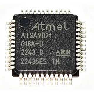
PIC24FJ128GU405-I/PT - 16-bit MCU, 128KB Flash, USB, LCD, 48-TQFP | Microchip
MPN: PIC24FJ128GU405-I/PT ✓ Hoạt độngPIC24FJ128GU405-I/PT Tóm tắt
A 16-bit microcontroller (MCU) is a processor core with a 16-bit data path and instruction word, sitting between 8-bit MCUs (used in simple control tasks) and 32-bit MCUs (used in high-performance applications). Within the embedded hierarchy, 16-bit MCUs occupy the power-management and connectivity sweet spot for human-machine interfaces, sensor aggregation, and USB peripherals. The PIC24FJ core family from Microchip extends this concept with Core Independent Peripherals (CIPs) that offload tasks such as PWM, ADC sequencing, and signal measurement from the CPU, reducing active-mode current and enabling longer battery life.
Key features of the PIC24FJ128GU405-I/PT include a maximum CPU speed of 32 MHz (8 MHz with 4x PLL), hardware Real-Time Clock and Calendar (RTCC), a 12-bit ADC with up to 200 ksps throughput, multiple communication interfaces (UART, SPI, I2C), and a segment LCD controller supporting up to 48 segments. The device operates across a wide 2V to 3.6V supply range and is offered in industrial temperature grade (-40C to +85C).
The device integrates a hardware DMA engine, a Crypto engine for AES/DES/SHA acceleration on select variants, and dual-partition Flash that allows a bootloader in one partition to update the application in the other without external storage. The USB 2.0 full-speed transceiver and PHY are embedded, eliminating external components for USB device applications.
Typical applications include low-power Human-Machine Interface (HMI) panels with LCD displays, USB-connected sensor hubs, industrial control panels, home automation gateways, and battery-powered metering equipment where the combination of LCD drive, USB, and OTA-friendly dual-partition Flash is required.
When designing with this MCU, choose decoupling capacitors (100 nF and 1 uF) close to each VDD/VSS pair and place the 32.768 kHz crystal within 5 mm of the SOSCO/SOSCI pins for accurate RTCC operation. Avoid routing high-frequency signals adjacent to the USB DP/DM traces to minimize EMI.
This page synthesizes distributor pricing, drop-in alternatives, and practical design notes not found in the manufacturer datasheet, giving embedded engineers a single source of parametric context for sourcing and second-source decisions.
Bộ thay thế dễ dàng lắp đặt cho PIC24FJ128GU405-I/PT — cùng gói, chân-to-chân tương thích. Các bộ phận yêu cầu hàn PCB bị loại trừ.
Các biến thể trong loạt này
Các mẫu cùng loạt có thể lắp đặt dễ dàng tương thích với PIC24FJ128GU405-I/PT (cùng hình factor và footprint) — khác nhau ở Package, ADC, LCD Controller, USB, Core Architecture.
PIC24FJ128GL405-I/PT
✅ Drop-InLiên hệ để biết giá
Xem tài liệu →PIC24FJ128GU410-I/PT
✅ Drop-InLiên hệ để biết giá
Xem tài liệu →PIC24FJ128GA410-I/PT
✅ Drop-InLiên hệ để biết giá
Xem tài liệu →PIC24FJ128GB410-I/PT
✅ Drop-InLiên hệ để biết giá
Xem tài liệu →PIC24FJ128GL406-I/PT
✅ Drop-InLiên hệ để biết giá
Xem tài liệu →PIC24FJ128GU405-I/PT Tỷ lệ tối đa & tính chất điện
| Core Architecture | PIC24FJ (16-bit RISC) |
| Program Memory (Flash) | 128 KB ECC Flash |
| RAM | 32 KB |
| Maximum CPU Speed | 32 MHz (16 MIPS) |
| Supply Voltage Range | 2.0 V to 3.6 V |
| Nhiệt độ hoạt động | -40C to +85C (Industrial) |
| Hộp | 48-pin TQFP (7x7 mm) |
| Kiểu lắp đặt | Surface Mount |
| USB | Full-Speed USB 2.0 Device (integrated PHY) |
| LCD Driver | Segment LCD controller (up to 48 segments) |
| ADC | 12-bit, up to 200 ksps |
| Communication Interfaces | UART, SPI, I2C |
| Timers | Multiple 16-bit and 32-bit timers |
| RTCC | Hardware Real-Time Clock and Calendar |
| DMA | Hardware DMA engine |
| Flash Partitioning | Dual Partition (OTA update support) |
| Trạng thái RoHS | Compliant |
| Cấp MSL | 3 (168 hours) |
Cấu hình chân PIC24FJ128GU405-I/PT
| Chân 1 | RA0 — GPIO/Analog input AN0 |
| Chân 2 | RA1 — GPIO/Analog input AN1 |
| Chân 3 | RA2 — GPIO/Analog input AN2 |
| Chân 4 | RA3 — GPIO/Analog input AN3 |
| Chân 5 | RA4 — GPIO/Analog input AN4 |
| Chân 6 | RA5 — GPIO/Analog input AN5 |
| Chân 7 | RA6 — GPIO/Analog input AN6 |
| Chân 8 | RA7 — GPIO/Analog input AN7 |
| Chân 9 | VDD — Positive supply (2.0V to 3.6V) |
| Chân 10 | VSS — Ground reference |
| Chân 11 | RB0 — GPIO/Programming clock (PGEC) |
| Chân 12 | RB1 — GPIO/Programming data (PGED) |
| Chân 13 | RB2 — GPIO/AN8 |
| Chân 14 | RB3 — GPIO/AN9 |
| Chân 15 | RB4 — GPIO/AN10 |
| Chân 16 | RB5 — GPIO/AN11 |
| Chân 17 | RB6 — GPIO/AN12 |
| Chân 18 | RB7 — GPIO/AN13 |
| Chân 19 | RC0 — GPIO |
| Chân 20 | RC1 — GPIO |
| Chân 21 | RC2 — GPIO |
| Chân 22 | RC3 — GPIO |
| Chân 23 | RC4 — GPIO |
| Chân 24 | RC5 — GPIO |
| Chân 25 | RC6 — GPIO |
| Chân 26 | RC7 — GPIO |
| Chân 27 | RD0 — GPIO |
| Chân 28 | RD1 — GPIO |
| Chân 29 | RD2 — GPIO |
| Chân 30 | RD3 — GPIO |
| Chân 31 | RD4 — GPIO |
| Chân 32 | RD5 — GPIO |
| Chân 33 | RD6 — GPIO |
| Chân 34 | RD7 — GPIO |
| Chân 35 | RE0 — GPIO |
| Chân 36 | RE1 — GPIO |
| Chân 37 | RE2 — GPIO |
| Chân 38 | RE3 — GPIO |
| Chân 39 | RE4 — GPIO |
| Chân 40 | RE5 — GPIO |
| Chân 41 | RE6 — GPIO |
| Chân 42 | RE7 — GPIO |
| Chân 43 | D+ — USB D+ data line |
| Chân 44 | D- — USB D- data line |
| Chân 45 | VBUS — USB VBUS sense input |
| Chân 46 | VDD — Positive supply (2.0V to 3.6V) |
| Chân 47 | VSS — Ground reference |
| Chân 48 | RF0 — GPIO/Segment LCD COM0 |
Ứng dụng tiêu biểu
PIC24FJ128GU405-I/PT phù hợp cho 6 Áp dụngs: USB Sensor Hub, Low-Power HMI with Segment LCD, Industrial Control Panel, Battery-Powered Metering, Home Automation Gateway, USB Medical Accessory.
USB Sensor Hub
The PIC24FJ128GU405-I/PT is well suited for USB-connected multi-sensor hubs where integrated full-speed USB eliminates an external PHY, reducing BOM cost by $0.30-$0.50. With 128 KB ECC Flash and 32 KB RAM, it aggregates I2C/SPI sensor data while running a USB HID or CDC class stack at full-speed (12 Mbps). The 32 MHz CPU delivers 16 MIPS, comfortably handling 10 Hz sensor polling alongside USB enumeration and bulk transfers. Engineers typically pair this MCU with Microchip's MPLAB Harmony USB stack, and the on-chip DMA engine offloads bulk endpoint transfers from the CPU to lower active-mode power consumption by up to 40 percent compared to polled USB firmware.
Được đề xuất
Low-Power HMI with Segment LCD
The PIC24FJ128GU405-I/PT integrates a segment LCD driver supporting up to 48 segments, ideal for industrial control panels, metering displays, and appliance front panels. The wide 2.0V to 3.6V supply range and Core Independent Peripherals (CIPs) enable the CPU to remain in Sleep mode while CIPs refresh the LCD and scan keypads, achieving typical sleep currents below 5 uA. The 12-bit ADC at 200 ksps reads potentiometers and temperature sensors for the HMI, while the hardware RTCC keeps accurate time during Sleep for scheduled wake events. This combination is the canonical Microchip low-power HMI recipe.
Được đề xuất
Industrial Control Panel
Industrial control panels benefit from the PIC24FJ128GU405-I/PT's industrial temperature range (-40C to +85C), 32 KB RAM for protocol stacks (Modbus RTU over UART, SPI to gate drivers), and ECC Flash for reliability in noisy factory environments. Dual-partition Flash enables field firmware updates via USB stick or UART bootloader without external EEPROM, reducing downtime during commissioning. The 12-bit ADC handles analog sensor inputs (4-20 mA current loop, thermistor), while the hardware DMA engine supports background SPI transfers to isolated communication transceivers. CIP-based PWM and input capture enable precise motor or valve control loops without CPU intervention.
Được đề xuất
Battery-Powered Metering
Battery-powered metering applications such as gas, water, and electricity meters rely on the PIC24FJ128GU405-I/PT's ultra-low Sleep current, hardware RTCC with 32.768 kHz crystal support, and segment LCD driver for tamper-resistant displays. The dual-partition Flash supports secure firmware updates over the meter's infrared or wireless port without external storage. The 12-bit ADC at 200 ksps digitizes pulse outputs from metrology front-ends, while the on-chip DMA ensures deterministic ADC-to-memory transfers without CPU wake-up, maximizing battery life to 10+ years on a single lithium cell in typical metering duty cycles.
Được đề xuất
Home Automation Gateway
The PIC24FJ128GU405-I/PT serves as a low-cost home automation edge node connecting wireless sub-GHz or BLE sensors to a Wi-Fi gateway via its full-speed USB link. With 128 KB Flash it runs Microchip's MiWi or Zigbee PRO stack alongside a USB CDC bridge, while 32 KB RAM accommodates network tables for up to 50 child nodes. The hardware AES engine on related GU4 variants accelerates encrypted message processing, and the 12-bit ADC monitors supply rail health. CIP-based PWM drives status LEDs without CPU load, keeping idle power under 10 mW for always-on wall-powered gateways.
Được đề xuất
USB Medical Accessory
The PIC24FJ128GU405-I/PT's integrated USB and ECC Flash make it suitable for low-risk USB medical accessories such as patient thermometers, pulse oximeter dongles, and data-logging pill dispensers. ECC Flash detects and corrects single-bit errors, important for medical firmware reliability, while full-speed USB provides plug-and-play connectivity to host PCs. The segment LCD driver displays real-time readings without requiring an external display controller, and the wide operating voltage supports battery-powered portable designs. Engineers should pair the MCU with appropriate IEC 60601 isolation and verify final product compliance with applicable FDA or EU MDR standards.
Được đề xuất
Tóm tắt các sản phẩm được đề xuất
Dữ liệu tham khảo kỹ thuật cho PIC24FJ128GU405-I/PT — so sánh, hướng dẫn thiết kế và thông tin tuân thủ.
Hướng dẫn chọn lựa
So sánh với các sản phẩm thay thế
| Tham số | Sản phẩm này | PIC24FJ128GL405-I/PT | PIC24FJ128GU410-I/PT | PIC24FJ128GA410-I/PT | PIC24FJ128GB410-I/PT |
|---|---|---|---|---|---|
| Brand | Microchip Technology | Microchip Technology | Microchip Technology | Microchip Technology | Microchip Technology |
| Package | 48-pin TQFP (7x7 mm) | 48-pin TQFP (7x7 mm) | 48-pin TQFP (7x7 mm) | 48-pin TQFP (7x7 mm) | 48-pin TQFP (7x7 mm) |
| Core | PIC24FJ (16-bit, 16 MIPS) | PIC24FJ (16-bit, 16 MIPS) | PIC24FJ (16-bit, 16 MIPS) | PIC24FJ (16-bit, 16 MIPS) | PIC24FJ (16-bit, 16 MIPS) |
| Flash | 128 KB | 128 KB | 128 KB | 128 KB | 128 KB |
| RAM | 32 KB | 32 KB | 32 KB | 32 KB | 32 KB |
| USB | Full-Speed USB 2.0 Device | No USB | Full-Speed USB 2.0 Device | Full-Speed USB 2.0 Device | Full-Speed USB 2.0 Device |
| Dual-Partition Flash (OTA) | Yes | Yes | Yes | No | No |
| Supply Voltage | 2.0V to 3.6V | 2.0V to 3.6V | 2.0V to 3.6V | 2.0V to 3.6V | 2.0V to 3.6V |
| Temperature Grade | -40C to +85C (Industrial) | -40C to +85C (Industrial) | -40C to +85C (Industrial) | -40C to +85C (Industrial) | -40C to +85C (Industrial) |
Bảo phân biệt quan trọng
- Dual-partition Flash for OTA firmware updates (vsPIC24FJ128GA410-I/PT)
- Integrated full-speed USB 2.0 with on-chip PHY (vsPIC24FJ128GL405-I/PT)
- Core Independent Peripherals (CIPs) for ultra-low-power operation (vsPIC24FJ128GB410-I/PT)
Ghi chú thiết kế
The PIC24FJ128GU405-I/PT requires a stable 2.0V-3.6V supply; place a 100 nF decoupling capacitor within 5 mm of each VDD/VSS pair, plus a bulk 10 uF tantalum or ceramic capacitor at the regulator output. For USB applications, VBUS should be sensed on the dedicated VBUS pin to detect host attachment; connect VBUS through a voltage divider if your VDD exceeds 3.6V. Core Independent Peripherals (CIPs) can refresh the LCD and run ADC conversions in Sleep mode without waking the CPU, achieving typical sleep currents below 5 uA.
Route USB D+ and D- traces as a 90 ohm differential pair with length matching within 2 mm, keeping them away from high-frequency switching nodes and clock traces to minimize EMI. Place the 48-pin TQFP land pattern with 0.4 mm-wide pads and per IPC-7351 nominal density rules. The exposed thermal pad (if present on the chosen variant) should be soldered to a 4 mm x 4 mm copper pour with at least 4 thermal vias to the ground plane.
Avoid configuring the internal PLL above 32 MHz or operating the part below 2.0V, as this causes Flash read errors not caught by ECC. When using the 32.768 kHz crystal for RTCC, place the crystal within 5 mm of the SOSCO/SOSCI pins and guard the traces with a ground ring to prevent coupling from switching nodes. If dual-partition OTA updates are used, allocate at least 50 percent of Flash to each partition to ensure the bootloader has room for the new image plus a fallback copy.
Thông tin tuân thủ
RoHS and REACH compliant per Microchip product page; not AEC-Q100 qualified - the industrial temperature grade (-40C to +85C) is rated but automotive qualification is not indicated in the provided data.