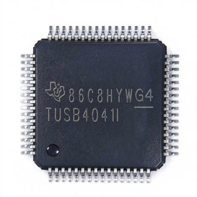
What is the TUSB4041IPAPR and what is currently available?
The Texas Instruments TUSB4041IPAPR is a four-port USB 2.0 hub controller in an HTQFP-64 (PAP) package measuring 10 x 10 mm. It supports 480 Mbps high-speed or 12 Mbps full-speed operation upstream, while each of its four downstream ports supports high-speed, full-speed, or low-speed devices. Key verified specifications include a 3.0 V to 3.6 V supply range, a -40C to +85C industrial temperature range, 1.5 kV HBM ESD protection on USB lines, per-port power-switch control, and BC1.2 charging detection. The part has an active lifecycle status, 32,360 units in stock, and an MOQ of 1. Pricing is verified as of 2026-11-01, with a 1-piece price of $5.625 and a 1,000-piece price of $3.2813 per unit.
Use the TUSB4041IPAPR product page to review current purchasing data, and consult the XAIPART component catalog when evaluating sourcing options.
| Verified parameter | TUSB4041IPAPR value |
|---|---|
| Function | USB hub controller |
| Protocol | USB 2.0 |
| Downstream ports | 4 |
| Upstream speed | 480 Mbps high-speed / 12 Mbps full-speed |
| Downstream speed support | High-speed / full-speed / low-speed |
| Supply voltage | 3.0 V to 3.6 V |
| Operating temperature | -40C to +85C, industrial |
| Package | HTQFP-64 (PAP), 10 x 10 mm |
| ESD protection | 1.5 kV HBM on USB lines |
| Configuration interface | I2C / EEPROM |
Action: Treat the TUSB4041IPAPR as an active, currently stocked option for a four-port USB 2.0 hub, and confirm the present distributor quote before releasing a production order.
How do you select and design in the TUSB4041IPAPR?
Select the TUSB4041IPAPR when the design needs one upstream USB 2.0 connection, four downstream ports, industrial-temperature operation, and per-port power management in a single controller. Its integrated USB transceivers support both self-powered and bus-powered hub configurations. The controller also provides I2C/EEPROM configuration for vendor ID, product ID, and port-remap policy, while BC1.2 CDP/SDP detection provides downstream battery-charging detection.
Start with the system-level port and power requirements
The device provides exactly four downstream ports. Each port has a dedicated power-switch control output and overcurrent flag input, allowing the system to use discrete downstream power switches and retain fault status for each port. The upstream connection supports 480 Mbps high-speed or 12 Mbps full-speed operation, while downstream devices can operate at high, full, or low speed.
| Design interface | Verified implementation | Engineering action |
|---|---|---|
| Upstream USB | DP_UP and DM_UP | Route the upstream differential pair according to the device datasheet and system layout. |
| Downstream USB | DP1/DM1 through DP4/DM4 | Provide a differential route for every enabled downstream port. |
| Port power | PWRCTL1 through PWRCTL4 | Connect each output to the control input of the appropriate downstream power-switch arrangement. |
| Port fault feedback | OVC1 through OVC4 | Route each overcurrent flag to the system so a faulted port can be identified. |
| Configuration | SCL and SDA | Use I2C/EEPROM configuration for the required VID, PID, and port-remap policy. |
Place the 27-ohm series termination resistors close to the USB DP and DM pins, as specified in the verified product description. Provide adequate bulk capacitance on each downstream VBUS rail managed by the controller's power-switch enables. Verify the final routing, power-distribution network, and connector requirements against the official datasheet before fabrication.
Plan power, reset, clocking, and configuration
The supplied pinout identifies VDD33 at pins 1, 28, and 40 and VDD_PLL at pin 52. The verified supply range is 3.0 V to 3.6 V, so the power design must remain inside that range under normal operating conditions. The pinout also identifies multiple ground pins for device return routing.
| Function group | Relevant verified pins | Design consideration |
|---|---|---|
| Supply | VDD33: 1, 28, 40; VDD_PLL: 52 | Provide the specified 3.0 V to 3.6 V operating supply and route ground connections appropriately. |
| Reset | GRSTz: 8 | GRSTz is an active-low global reset. |
| Clock | XTAL1: 29; XTAL2: 30; CLK_OUT: 31 | The pinout specifies a 12 MHz crystal and a 60 MHz reference output. |
| Reference | R1: 7 | Connect R1 to ground through 10 kohm. |
| Configuration | CFG_SEL: 47; FULLPWR: 48; SPEED: 46 | Use the documented strap and I2C/EEPROM configuration options. |
| Test and JTAG | TEST: 33; TMS: 34; TCK: 35; TDI: 36; TDO: 37; TRSTz: 38 | Tie TEST to ground for normal operation and handle the test pins according to the datasheet. |
Pin 5, ID, is marked not connected for hub applications. Several other positions are explicitly listed as NC. Do not assign functions to those pins without checking the complete pin table and datasheet.
Use the application data to select operating scenarios
The verified application data supports industrial PC expansion, docking stations, monitors with built-in hubs, embedded HMI panels, POS terminals, automotive infotainment accessory hubs, and medical USB device aggregation. These scenarios share a need for multiple USB 2.0 ports, managed VBUS, device identification, and reliable operation across -40C to +85C.
The TUSB4041IPAPR is suitable for industrial and embedded systems, but the verified FAQ states that it is not AEC-Q100 qualified. For automotive programs that mandate AEC-Q100 qualification, the supplied data identifies the TUSB4041IPAPQ1 as the same-package alternative. The industrial variant may still be considered for non-regulated vehicle-related equipment when the qualification requirement does not apply.
Action: Freeze the port count, VBUS architecture, clock source, configuration method, and qualification target before layout; these choices determine the surrounding component set and PCB decisions.
Which alternatives can replace the TUSB4041IPAPR, and are they drop-in replacements?
The verified alternatives dataset does not establish a pin-compatible drop-in replacement in the HTQFP-64 (PAP) footprint. It identifies the TUSB4020BIPHP as the nearest supplied alternative, but that device has two downstream ports and uses a smaller HTQFP-48 package. The package difference requires PCB rework, so the TUSB4020BIPHP is not a board-level drop-in replacement.
| Parameter | TUSB4041IPAPR | TUSB4020BIPHP |
|---|---|---|
| Downstream ports | 4 | 2 |
| Package | HTQFP-64 (PAP), 10 x 10 mm | HTQFP-48 |
| PCB replacement status | Reference device | NOT PCB drop-in |
| Selection implication | Use when four downstream ports are required. | Use only when a two-port design and corresponding PCB change are acceptable. |
The TUSB4041IPAPQ1 appears in the verified FAQ as an AEC-Q100 automotive-qualified member of the same family using the HTQFP-64 (PAP) package. That makes it the relevant same-package option for an automotive qualification requirement, but the supplied prompt does not provide a complete independent specification set for a side-by-side table comparison.
Do not substitute the TUSB4020BIPHP based only on the shared USB hub function. Its two-port count changes the product architecture, and its HTQFP-48 package changes the footprint. A board intended around the TUSB4041IPAPR requires layout, assembly, and qualification review before any substitution.
Action: Use the TUSB4020BIPHP only for a new two-port design that explicitly accepts the HTQFP-48 footprint; retain a same-package engineering review for any automotive replacement.
What does the lifecycle and supply data say about the TUSB4041IPAPR?
The verified lifecycle status is active. The XAIPART database lists 32,360 units in stock with an MOQ of 1, so the component is currently orderable without a large minimum buy. The verified price structure provides procurement options from one unit through 1,000 units.
| Quantity threshold | Verified unit price as of 2026-11-01 |
|---|---|
| 1 or more | $5.625 |
| 10 or more | $4.0625 |
| 100 or more | $3.5937 |
| 500 or more | $3.4375 |
| 1,000 or more | $3.2813 |
These figures describe current availability and price points, not a forecast of future supply. The provided lifecycle and stock data does not include a lead-time value, forecast, authorized-distributor count, or market-share statement, so procurement should not infer any of those conditions from the inventory figure alone.
The active status and listed inventory reduce sourcing risk for an initial build, but they do not replace a production-time quote or allocation review. For scheduled builds, request a dated quotation and confirm the authorized-channel lead time directly with the supplier.
For broader sourcing context, review the XAIPART Blog, then compare current inventory, lifecycle status, MOQ, and volume pricing against the project's schedule.
Action: Validate availability at the planned build date and obtain a current production quotation; do not lock a schedule around the listed 32,360-unit stock without supplier confirmation.
What should buyers watch as USB hub requirements evolve?
The most important trend to evaluate is the gap between a 480 Mbps USB 2.0 hub and newer connectivity requirements. The TUSB4041IPAPR remains well matched to USB 2.0 peripherals, including keyboards, mice, scanners, printers, storage, and configuration devices. However, its verified upstream ceiling is 480 Mbps and its port count is fixed at four. Designs that later require USB 3.0 SuperSpeed, USB Type-C, Power Delivery, or more than four downstream ports should evaluate a different controller family before layout is frozen.
Second, monitor the role of charging and configuration in downstream ports. The integrated BC1.2 CDP/SDP detection can support downstream battery-charging requirements, while I2C/EEPROM configuration allows an OEM to set VID, PID, and port-remap policy. These functions can reduce the need for separate support circuitry when the product requires those exact capabilities.
Third, preserve qualification headroom. The verified -40C to +85C range covers industrial-temperature operation, but it does not replace AEC-Q100 qualification for automotive systems. Designs that may enter a regulated automotive program should evaluate the Q1 variant identified in the verified FAQ rather than treating the industrial part as an automatic substitute.
Finally, watch the electrical requirements around each port. The part provides per-port power-switch control outputs and overcurrent flag inputs, but the final design still depends on the downstream power architecture, USB data routing, 27-ohm series termination placement, clock implementation, and 3.0 V to 3.6 V supply operation. Those verified constraints are more important to long-term design stability than a broad market trend.
| Requirement direction | Verified TUSB4041IPAPR capability | Buyer decision |
|---|---|---|
| Higher data rate | Up to 480 Mbps high-speed | Confirm that USB 2.0 bandwidth meets the product requirement before committing the hub architecture. |
| More ports | 4 downstream ports | Validate device count and connector layout against the fixed port count. |
| Device charging | BC1.2 CDP/SDP detection | Use the integrated detection only where the application requires that charging approach. |
| Product identity | I2C/EEPROM configuration | Plan VID, PID, and port-remap data before firmware and production configuration. |
| Automotive qualification | Industrial -40C to +85C rating; not AEC-Q100 qualified | Use the Q1 option when the automotive qualification requirement applies. |
Action: Lock the bandwidth, port-count, charging, configuration, and qualification requirements before schematic release, then recheck the controller choice if any of those requirements are expected to expand.
留言
成為第一個留言的人。
🔐 請 登入 即可送出留言。
還沒有帳戶嗎? 註冊