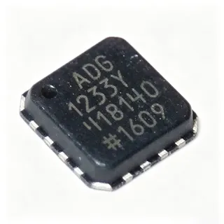
ADRF5721 - 4-Bit Digital Attenuator 9kHz-40GHz | Analog Devices
MPN: ADRF5721 ✓ 啟用中ADRF5721 概覽
A digital attenuator is a type of RF component that reduces the amplitude of a signal by a controlled amount, typically using switched resistor networks or PIN diodes. It is a key building block in RF front-ends, enabling precise gain control in transceivers, test equipment, and radar systems. The ADRF5721 belongs to the family of RF attenuators, which are essential for signal conditioning and power leveling in communication systems.
Key features of the ADRF5721 include a 30 dB attenuation range with 2 dB steps, 50 Ω characteristic impedance, and RF input power handling of 26 dBm average and 30 dBm peak for all states. The device is pin compatible with the ADRF5731, a fast switching version operating from 100 MHz to 40 GHz, allowing design flexibility. The LGA package is ideal for space-constrained designs, and the wide frequency range covers everything from HF to Ka-band.
The ADRF5721 uses a silicon process that provides high linearity and consistent performance across frequency. The 4-bit control interface allows 16 attenuation states, from 0 dB to 30 dB, with monotonic behavior. The device is designed for 50 Ω systems, ensuring minimal VSWR and predictable insertion loss. The ATTIN port can handle up to 26 dBm average power, making it robust for transmitter and receiver applications.
Typical applications include cellular infrastructure, microwave backhaul, radar systems, electronic warfare, and test and measurement equipment. The wide frequency range and high power handling make it versatile for both commercial and military RF systems. In a 5G base station, the ADRF5721 can be used in the transmit path to adjust output power, or in the receive path to prevent overload.
When designing with the ADRF5721, ensure proper grounding and decoupling on the control pins to avoid digital noise coupling into the RF path. The LGA package requires a well-designed PCB layout with adequate thermal vias for heat dissipation. The device is RoHS compliant and lead-free, meeting modern environmental standards.
直接替換替代品,適用於 ADRF5721 — 相同封裝,腳位對腳位相容。需重新設計 PCB 的不同封裝零件不列入。
此系列的變體
與下列產品可直接替換的同系列型號: ADRF5721 (相同外形與佔位) — 差異在於 Attenuation Range, Control Interface, Insertion Loss, Package, Pin Compatibility.
ADRF5731BCCZN
✅ 直接替換📋 參考替代品(不在目錄中)
ADRF5720BCCZN
✅ 直接替換 ⚠️ 規格未經驗證📋 參考替代品(不在目錄中)
ADRF5740BCCZN
✅ 直接替換 ⚠️ 規格未經驗證📋 參考替代品(不在目錄中)
PE43711A
✅ 直接替換 ⚠️ 規格未經驗證📋 參考替代品(不在目錄中)
HMC472ALP4E
✅ 直接替換 ⚠️ 規格未經驗證📋 參考替代品(不在目錄中)
ADRF5721 規格
| Type | Silicon 4-bit digital attenuator |
| Attenuation Range | 30 dB |
| Attenuation Step | 2 dB |
| Frequency Range | 9 kHz to 40 GHz |
| Insertion Loss | 3.4 dB (max) |
| Impedance | 50 Ω |
| RF Input Power (Average) | 26 dBm |
| RF Input Power (Peak) | 30 dBm |
| Control Interface | 4-bit parallel |
| 封裝 | 16-terminal LGA, 2.5 mm × 2.5 mm |
| 工作溫度 | -40°C to +105°C |
| RoHS | Compliant |
| Lead-Free | Yes |
| 安裝類型 | Surface Mount |
| Pin Compatibility | Pin compatible with ADRF5731 |
ADRF5721 腳位配置
| 腳位 1 | ATTIN — RF input |
| 腳位 2 | GND — Ground |
| 腳位 3 | D0 — Control bit 0 (LSB) |
| 腳位 4 | D1 — Control bit 1 |
| 腳位 5 | D2 — Control bit 2 |
| 腳位 6 | D3 — Control bit 3 (MSB) |
| 腳位 7 | LE — Latch enable |
| 腳位 8 | SEROUT — Serial output for daisy chaining |
| 腳位 9 | GND — Ground |
| 腳位 10 | ATTOUT — RF output |
| 腳位 11 | GND — Ground |
| 腳位 12 | GND — Ground |
| 腳位 13 | GND — Ground |
| 腳位 14 | GND — Ground |
| 腳位 15 | GND — Ground |
| 腳位 16 | GND — Ground |
典型應用
ADRF5721 適用於 6 應用s: 5G Infrastructure, Radar Systems, Test and Measurement, Electronic Warfare, Satellite Communications, Microwave Backhaul.
5G Infrastructure
The ADRF5721 is ideal for 5G base stations and small cells, providing precise gain control in transmit and receive paths. Its wide frequency range up to 40 GHz covers mmWave bands, and its high power handling of 26 dBm average ensures robust performance. The low insertion loss of 3.4 dB helps maintain signal integrity, while the 4-bit interface allows fast attenuation adjustments for dynamic power control.
推薦
Radar Systems
In radar systems, the ADRF5721 is used for gain leveling and protection. Its 30 dB attenuation range in 2 dB steps allows precise control of signal levels, while the 50 Ω impedance ensures compatibility with standard RF components. The device operates from 9 kHz to 40 GHz, covering various radar bands, and can handle peak power up to 30 dBm, making it suitable for high-power transmit/receive modules.
推薦
Test and Measurement
The ADRF5721 is widely used in test equipment such as signal generators, spectrum analyzers, and network analyzers. Its wide frequency range and precise attenuation steps enable accurate signal level setting. The 4-bit parallel interface simplifies integration with microcontrollers, and the compact LGA package saves board space. The device's high linearity ensures minimal distortion in measurement paths.
推薦
Electronic Warfare
In electronic warfare systems, the ADRF5721 provides fast and accurate attenuation for signal conditioning and jamming. Its wide frequency range from 9 kHz to 40 GHz covers multiple bands, and the high power handling of 26 dBm average ensures reliability in harsh environments. The device's small size and low insertion loss are critical for compact, high-performance EW modules.
推薦
Satellite Communications
The ADRF5721 is used in satellite communication systems for gain control in both uplink and downlink paths. Its frequency range up to 40 GHz covers Ku, Ka, and V bands, and the 50 Ω impedance matches standard satellite RF components. The device's low insertion loss and high power handling make it suitable for high-throughput satellite systems, while the 4-bit control allows precise power leveling.
推薦
Microwave Backhaul
In microwave backhaul systems, the ADRF5721 is used for automatic gain control and power leveling. Its wide frequency range from 9 kHz to 40 GHz covers common backhaul bands, and the 30 dB attenuation range provides sufficient adjustment. The device's high power handling and low insertion loss ensure reliable performance in point-to-point links, while the compact package simplifies integration into outdoor units.
推薦
推薦產品摘要
工程參考資料,適用於 ADRF5721 — 比較、設計指引及合規資訊。
選型指南
與替代品比較
| 參數 | 本產品 | ADRF5731BCCZN | ADRF5720BCCZN | ADRF5740BCCZN | PE43711A | HMC472ALP4E |
|---|---|---|---|---|---|---|
| Package | 16-terminal LGA | 16-terminal LGA | 16-terminal LGA | 16-terminal LGA | 16-terminal LGA | 16-terminal LGA |
| Brand | Analog Devices | Analog Devices | Analog Devices | Analog Devices | pSemi | Analog Devices |
| Frequency Range | 9 kHz to 40 GHz | 100 MHz to 40 GHz | 9 kHz to 40 GHz | 9 kHz to 40 GHz | 9 kHz to 40 GHz | DC to 3.8 GHz |
| Attenuation Range | 30 dB | 30 dB | 31.5 dB | 15.5 dB | 31 dB | 31.5 dB |
| Step Size | 2 dB | 2 dB | 0.5 dB | 0.5 dB | 0.5 dB | 0.5 dB |
| Insertion Loss | 3.4 dB | 3.4 dB | 3.4 dB | 3.4 dB | 2.5 dB | 2.5 dB |
| RF Input Power (Average) | 26 dBm | 26 dBm | 26 dBm | 26 dBm | 30 dBm | 24 dBm |
| Control Interface | 4-bit parallel | 4-bit parallel | 6-bit parallel | 5-bit parallel | SPI | 6-bit parallel |
主要差異化特點
- Wide frequency range from 9 kHz to 40 GHz (對比HMC472ALP4E)
- High power handling of 26 dBm average (對比HMC472ALP4E)
- Pin compatible with ADRF5731 (對比PE43711A)
設計說明
Ensure proper grounding and thermal management for the LGA package. Use multiple vias under the exposed pad to connect to the ground plane, and follow the recommended PCB layout in the datasheet to minimize parasitic inductance and ensure optimal RF performance.
Keep RF traces as short as possible and use controlled impedance (50 Ω) lines. Place decoupling capacitors close to the control pins to filter digital noise, and avoid routing high-speed digital signals near the RF path to prevent coupling.
Do not exceed the maximum RF input power of 30 dBm peak, as this can damage the device. Also, ensure the control interface is properly latched to avoid unintended attenuation states. Refer to the datasheet for timing requirements of the LE and data pins.
合規資訊
RoHS compliant per datasheet. Lead-free. No AEC-Q100 qualification indicated.