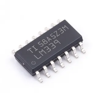
LM2902KAVQDRQ1 - Quad 30V 1.2MHz Op Amp | Texas Instruments
MPN: LM2902KAVQDRQ1 ✓ 啟用中LM2902KAVQDRQ1 概覽
An operational amplifier is an analog integrated circuit that amplifies the voltage difference between its non-inverting and inverting inputs. The LM2902 contains four independent, internally compensated amplifiers, allowing one package to provide feedback control, buffering, signal conditioning, or differential-to-single-ended conversion. In the power-management hierarchy, it is an analog signal-chain IC rather than a voltage regulator, although its wide supply tolerance makes it useful in industrial and automotive power systems.
The headline specifications include four amplifier circuits, a 1.2 MHz gain-bandwidth product, a 0.5 V/us slew rate, and approximately 2 mV offset voltage. The device also provides a typical common-mode rejection ratio of 80 dB and an input bias current of 20 nA. Its 30 V operating capability suits 12 V automotive systems, industrial control equipment, audio electronics, and instrumentation while allowing operation from lower single-supply voltages.
Each amplifier is frequency compensated and optimized for general-purpose analog design rather than high-speed differential signaling. A 1.2 MHz gain-bandwidth product is most useful at moderate closed-loop gains, while the 0.5 V/us slew rate limits large-signal response at low frequencies. The four independent channels can be configured independently for noninverting, inverting, comparator-like, summing, and feedback-amplifier circuits, subject to common-mode and output-swing limitations.
Typical uses include automotive sensor interfaces, battery-powered monitoring equipment, active filters, audio preamplifiers, industrial transducers, and general-purpose control loops. Four amplifiers in one SOIC-14 package reduce board area and component count when several low-frequency analog channels are required. The automotive qualification makes the LM2902-Q1 family especially suitable for body electronics, actuator interfaces, and vehicle sensing systems.
Design with the supply voltage, input common-mode range, output swing, input bias current, and capacitive-load drive in mind. Decoupling capacitors should be placed close to the supply pins, and sensitive input traces should be kept away from switching nodes. Because the gain-bandwidth and slew-rate limits are modest, verify stability with the intended feedback network and load capacitance before scaling the design into production.
This page combines manufacturer specifications, lifecycle information, application guidance, and same-footprint alternatives. It also provides practical design notes and parameter comparisons that help engineers distinguish functionally similar LM2902 variants and choose a suitable replacement without assuming that every ordering code is electrically identical.
直接替換替代品,適用於 LM2902KAVQDRQ1 — 相同封裝,腳位對腳位相容。需重新設計 PCB 的不同封裝零件不列入。
此系列的變體
與下列產品可直接替換的同系列型號: LM2902KAVQDRQ1 (相同外形與佔位) — 差異在於 Maximum Supply Voltage, Amplifier Type, Input Bias Current, Operating Temperature Range, RoHS Status.
LM2902KVQDRQ1
✅ 直接替換聯絡詢價
查看資料表 →LM2902KVQDRG4Q1
✅ 直接替換聯絡詢價
查看資料表 →LM2902QDRG4Q1
✅ 直接替換聯絡詢價
查看資料表 →LM2902BKVQDRQ1
✅ 直接替換📋 參考替代品(不在目錄中)
LM2902KAVQDRQ1 最大額定值與電氣特性
| Number of Amplifier Circuits | 4 circuits |
| Maximum Supply Voltage | 30 V |
| Gain-Bandwidth Product | 1.2 MHz |
| Input Offset Voltage | 2 mV |
| Slew Rate | 0.5 V/us |
| Input Bias Current | 20 nA |
| Common-Mode Rejection Ratio | 80 dB |
| Enhanced ESD Rating | 2 kV |
| 工作溫度範圍 | -55 C to +125 C |
| Supply Voltage in Test Condition | 5 V |
| Amplifier Type | General-purpose operational amplifier |
| 腳位數 | 14 pins |
| Package Type | SOIC-14 |
| 安裝類型 | Surface mount |
| Packaging | Tape and reel |
| Automotive Qualification | AEC-Q100 qualified |
| RoHS 狀態 | Compliant |
| MSL | 1 - 260 C unlimited floor life |
| Product Status | Active |
LM2902KAVQDRQ1 soic-14 腳位配置指南
LM2902KAVQDRQ1(soic-14 封裝)的腳位配置。 此類比元件具有輸入、輸出與電源腳位。偏移歸零、補償與致能腳位配置請參閱製造商資料表。適用於訊號調理與放大器電路。
無詳細腳位定義資料: LM2902KAVQDRQ1.
請參閱 資料表 以查看完整腳位配置。
典型應用
LM2902KAVQDRQ1 適用於 6 應用s: Automotive Sensor Signal Conditioning, Industrial Transducer Interface, Active Audio Preamp, Battery-Powered Monitoring System, Power Supply Feedback Control, Data Acquisition Front End.
Automotive Sensor Signal Conditioning
The LM2902KAVQDRQ1 fits automotive sensor interfaces that need several low-frequency amplification stages in a compact package. Its four independent channels can condition resistive, resistive-divider, or low-current sensor outputs while the 30 V maximum supply and -55 C to +125 C operating range support demanding vehicle environments. The 1.2 MHz gain-bandwidth product is appropriate for bandwidths far below the amplifier limit, and the 20 nA input bias current helps avoid loading high-impedance sources. AEC-Q100 qualification makes the LM2902-Q1 family suitable for automotive qualification programs when the exact ordering code is confirmed. Practical designs should still check the input common-mode range, output swing, sensor excitation noise, and fault margins.
推薦
Industrial Transducer Interface
The LM2902KAVQDRQ1 is useful for buffering and amplifying low-level industrial transducer signals when one board must process several analog channels. Its four internal amplifiers can implement non-inverting stages, active filters, differential-to-single-ended conversion, and output drivers without using four separate packages. A 1.2 MHz gain-bandwidth product supports moderate closed-loop gains, while the 0.5 V/us slew rate is suitable for slow sensor and control signals rather than high-speed communications. The wide 30 V supply capability simplifies interface design around 24 V industrial systems, provided each input and output remains inside the specified common-mode and swing limits. Use short feedback routes, local supply decoupling, and guarded input traces to reduce noise pickup.
推薦
Active Audio Preamp
The LM2902KAVQDRQ1 can form a low-cost four-channel audio preamplifier for line-level signals in automotive, industrial, or communication equipment. Its four independent amplifier channels support multiple stereo or mono stages, and the 1.2 MHz gain-bandwidth product provides ample response for audio-band amplification. The 0.5 V/us slew rate is comfortably above the demands of most audio signals but does not make the device appropriate for wideband video or high-frequency signal paths. The 2 mV input offset is reasonable for general audio conditioning. Designers should provide adequate output-current margin for the chosen load, check the output swing on the selected supply, and bypass the supply pins close to the package to prevent channel-to-channel modulation.
推薦
Battery-Powered Monitoring System
The LM2902KAVQDRQ1 fits battery-powered environmental and equipment monitors that require several amplification functions at modest signal bandwidth. It can combine sensor buffering, gain-stage amplification, active filtering, and a comparator-style control amplifier in one SOIC-14 package. The 20 nA input bias current is beneficial when driving high-impedance sensors, and the four-channel integration reduces both board area and component count. Because the gain-bandwidth product is 1.2 MHz and the slew rate is 0.5 V/us, the device is best suited to slow or audio-band monitoring signals. Verify the current drawn by the complete circuit, confirm that the supply remains within the allowed range, and include protection against transients when the device is connected to long external leads.
推薦
Power Supply Feedback Control
The LM2902KAVQDRQ1 can implement error amplifiers and feedback-control elements in linear or supervisory power circuits because it combines four compensated amplifiers with a 30 V maximum supply. One channel may amplify the feedback error, while remaining channels provide signal conditioning, filtering, or auxiliary control functions around a switching or linear regulator. Its 1.2 MHz bandwidth and 0.5 V/us slew rate suit compensation loops operating at moderate frequencies. The key design constraint is loop stability: select feedback and compensation components against the amplifier and load characteristics, check the output-current capability, and keep the feedback node away from switching nodes. Automotive implementations should use the correctly qualified ordering code and apply the program's component and process-change controls.
推薦
Data Acquisition Front End
The LM2902KAVQDRQ1 is applicable to the analog front end of a moderate-speed data-acquisition system requiring multiple amplifier channels. The four channels can perform instrumentation-style differential conversion, gain, filtering, and driver functions before a higher-resolution converter. Its 80 dB common-mode rejection ratio is useful when the signal is small relative to the common-mode voltage, although the application must remain within the input common-mode range. The 1.2 MHz gain-bandwidth product and 2 mV offset are suitable for many low-to-moderate-resolution systems, but they are not sufficient by themselves for precision or high-speed conversion. Keep input paths short, use matched resistors for differential networks, and decouple each supply connection close to the device.
推薦
推薦產品摘要
工程參考資料,適用於 LM2902KAVQDRQ1 — 比較、設計指引及合規資訊。
選型指南
與替代品比較
| 參數 | 本產品 | LM2902KVQDRQ1 | LM2902KVQDRG4Q1 | LM2902QDRG4Q1 | LM2902BKVQDRQ1 | LM2902DR |
|---|---|---|---|---|---|---|
| Package | SOIC-14 | SOIC-14 - same | SOIC-14 - same | SOIC-14 - same | SOIC-14 - same | SOIC-14 - same |
| Brand | Texas Instruments | Texas Instruments | Texas Instruments | Texas Instruments | Texas Instruments | STMicroelectronics |
| Number of Amplifiers | 4 circuits | 4 circuits | 4 circuits | 4 circuits | 4 circuits | 4 circuits |
主要差異化特點
- Four automotive-qualified amplifiers in one package (對比LM2902DR)
- Direct same-package family review (對比LM2902KVQDRQ1)
- Extended-temperature automotive application range (對比LM2902QDRG4Q1)
- Upgraded high-voltage family alternative (對比LM2902BKVQDRQ1)
設計說明
Place the supply-decoupling capacitor immediately adjacent to the positive and negative supply pins of the SOIC-14 package. Because the package contains four amplifiers, shared supply impedance can allow disturbance on one channel to appear at the outputs of another. Keep non-inverting inputs, inverting inputs, and feedback components away from switching-regulator outputs and high-current return paths. Use a continuous ground reference beneath the device and route each channel's feedback loop on the same PCB layer to minimize parasitic pickup.
Do not interpret the 30 V maximum supply rating as permission to apply 30 V across every operating condition. Verify the input common-mode range, output-voltage swing, supply-current limits, and load capability for the selected gain and frequency. The 1.2 MHz gain-bandwidth product is well above the requirements of many sensor and audio applications, but noise gain, load capacitance, and feedback-network impedance can still affect stability. Start with the manufacturer’s recommended feedback values and validate the final board with the actual source and load impedances.
Estimated power dissipation is proportional to total supply voltage times the sum of all four amplifier currents plus quiescent current. With a 30 V maximum-supply design, a 1 mA total load would dissipate about 30 mW before layout losses; with a 10 mA total load, the estimate rises to about 300 mW. These calculations are estimates using the stated current assumptions, not maximum-power ratings. Check the SOIC-14 thermal resistance, copper area, ambient temperature, and automotive temperature-rise requirements at the highest expected load.
For high-impedance sensors, keep input leakage current and board contamination in mind because the specified input bias current is approximately 20 nA. Use protective resistors, guard traces, and clean board surfaces where necessary. The 80 dB common-mode rejection ratio helps reject common-mode noise, but it cannot correct a design that exceeds the input common-mode range or places sensitive nodes next to switching circuitry. Verify offset and bias errors against the sensor’s smallest meaningful signal before setting the closed-loop gain.
合規資訊
Texas Instruments states that the LM2902-Q1 family is qualified for automotive use in accordance with AEC-Q100 specifications. RoHS compliance is identified for LM2902KAVQDRQ1. REACH, lead-free, halogen-free, and conflict-minerals status were not established explicitly.