电流传感器
产品(4)
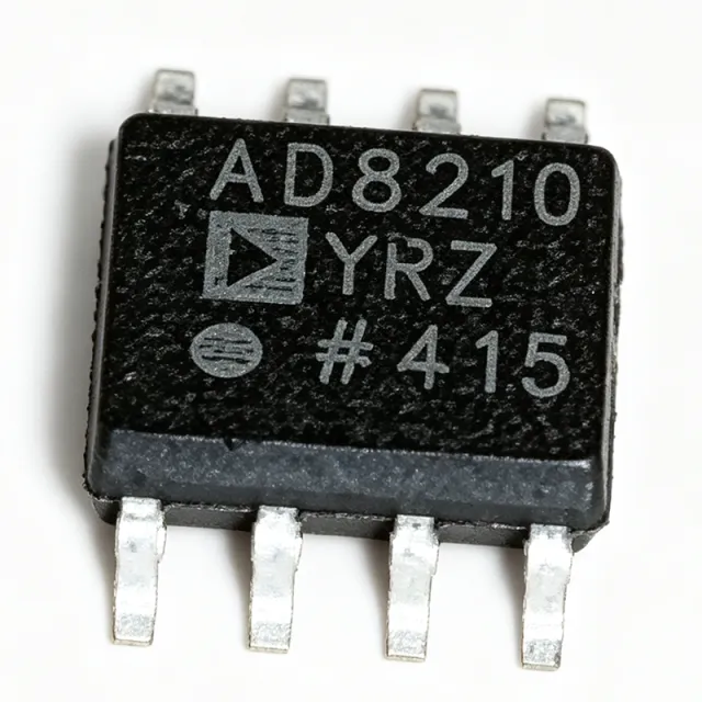
AD8210YRZ - High Voltage Bidirectional Current Shunt Monitor | Analog Devices
The AD8210YRZ is a high voltage, bidirectional current shunt monitor from Analog Devices, designed to amplify small differential voltages in the presence of large common-mode voltages. It operates from a single 5 V supply and features an input common-mode voltage range from -2 V to +65 V, making it ideal for high-side and low-side current sensing in automotive, industrial, and power management applications. The device is available in an 8-pin SOIC package and provides a 5 mA output current capability. A current shunt monitor is a specialized difference amplifier that measures the voltage drop across a sense resistor to determine load current. It is a critical component in power management systems, enabling precise current monitoring for battery management, motor control, and load protection. The AD8210 belongs to the family of current sense amplifiers, which are essential for closed-loop control and diagnostic functions in modern electronic systems. Key features of the AD8210YRZ include a wide common-mode input range, bidirectional current sensing capability, and excellent AC and DC performance. The device offers a typical supply current of 2 mA and a bandwidth of 450 kHz, ensuring accurate measurement of dynamic currents. Its high CMRR (typically 120 dB) rejects common-mode noise, making it suitable for noisy industrial environments. The AD8210 uses a precision difference amplifier architecture with an external shunt resistor, allowing flexible gain configuration. The output is referenced to a programmable level, enabling bidirectional current detection. The device includes an input filter to reduce high-frequency noise and supports both high-side and low-side sensing configurations. Typical applications include motor control, battery monitoring, power supply diagnostics, and load current sensing in automotive systems. The wide common-mode range and bidirectional capability make it particularly useful for H-bridge motor drivers and battery charge/discharge monitoring. When designing with the AD8210YRZ, ensure the shunt resistor is placed close to the load and the input filter components are optimized for the desired bandwidth. The output reference pins allow adjustment of the output voltage level, which is essential for interfacing with ADCs or comparators.

INA169NA/3K - 60V High-Side Current Sense Amplifier | TI
The Texas Instruments INA169NA/3K is a high-side, unipolar current shunt monitor designed for accurate current measurement in a wide range of applications. It operates from a 2.7V to 60V supply and common-mode voltage range, making it suitable for both low-voltage and high-voltage systems. The device is available in a 5-pin SOT-23 (DBV) package, offering a compact solution for space-constrained designs. A current sense amplifier is an integrated circuit that measures the voltage drop across a shunt resistor placed in series with a load, converting it to a proportional output current or voltage. The INA169 is a variable gain current sense amplifier, meaning its gain is set by a single external resistor, providing design flexibility. It belongs to the family of current shunt monitors, which are essential for power management, battery monitoring, and load detection in electronic systems. Key features of the INA169NA/3K include a wide input common-mode voltage range of 2.7V to 60V, a bandwidth of 440kHz, and a low quiescent current of 60µA (typical). The gain is set by a single resistor, allowing for precise scaling of the output. The device also features independent supply and input common-mode voltages, enabling operation with a lower supply voltage while sensing higher voltages. The SOT-23-5 package is ideal for portable and space-limited applications. Technically, the INA169 uses a bipolar process to achieve high accuracy and stability. The input offset voltage is typically 1000µV (max), and the output is a current proportional to the differential input voltage divided by the external gain resistor. This architecture allows for high-side sensing without disrupting the ground path, which is critical in many power systems. The device is specified for operation over the -40°C to +125°C temperature range, making it suitable for industrial and automotive environments. Typical applications include battery chargers, power supplies, motor control, and load monitoring in automotive and industrial systems. The INA169NA/3K is also used in portable devices where low quiescent current is essential. Its high bandwidth of 440kHz enables fast transient response, which is beneficial for detecting rapid load changes. When designing with the INA169NA/3K, ensure the shunt resistor is placed on the high side and the gain resistor is selected to provide the desired output current range. The output can be converted to a voltage with a load resistor to ground. Proper PCB layout, including Kelvin connections to the shunt, is recommended for accurate measurements.

IR2175STRPBF - 600V Linear Current Sense IC, 8-SOIC | Infineon
The Infineon IR2175STRPBF is a high-voltage monolithic linear current sensing IC housed in an 8-pin SOIC package, designed to measure phase current through an external shunt resistor in motor-drive and power-conversion systems. It accepts a differential input of ±260 mV across the shunt, integrates a floating high-side channel capable of operating up to +600 V common-mode, and delivers a digital PWM output proportional to load current for direct microcontroller interface. A current sense regulator (also called a linear current sensing IC) is a category of power-management IC that converts a small analog shunt voltage into an isolated, scaled, and noise-immune representation of load current. These ICs sit in the signal chain between a low-side shunt resistor and the controller, providing galvanic isolation between the power stage and logic. The IR2175 family belongs to Infineon's high-voltage gate-driver and sensor portfolio, positioned above simple op-amp current shunts and below isolated delta-sigma modulators. Key features include 9.5 V to 20 V low-side supply (VCC), 13 V to 20 V high-side floating supply (VB), 2 mA quiescent current on the bootstrap rail (IQBS), 20 mA output current capability, 130 kHz typical PWM output frequency, and ±260 mV input common-mode range with 20 ppm/°C gain temperature drift. An independent fast overcurrent trip signal activates within 2 µs typical delay when the input threshold is exceeded, providing hardware-level short-circuit protection independent of the PWM feedback path. Architecturally, the IR2175 combines a high-side differential amplifier with an internal level shifter, allowing the low-voltage DSP or MCU to read high-side phase current without external isolation. The monolithic integration of the floating channel eliminates optocoupler drift and propagation delay, supporting high-bandwidth FOC (field-oriented control) loops in variable-frequency drives. Typical applications include three-phase motor drives, HVAC compressors, industrial servo amplifiers, and EV traction inverters. The wide 600 V floating-channel range covers 230 V and 480 V rectified bus voltages with substantial headroom. Designers select the IR2175 when they need a simple, low-BOM current-feedback path for variable-speed drives. Designers should size the external shunt to keep peak current below ±260 mV, observe PCB creepage/clearance for the floating pins, and provide adequate bootstrap capacitance to sustain the high-side supply. Compared to discrete op-amp solutions, the IR2175 reduces part count and eliminates calibration of the gain drift. This page synthesizes distributor pricing, drop-in alternatives, and practical design notes not found in the manufacturer datasheet, helping procurement and firmware teams select, source, and validate a 600 V current-sense IC in a single document.

RTQ6060 - 36V Bidirectional Zero-Drift Current Monitor | Richtek
The Richtek RTQ6060 is a high-precision, bidirectional, zero-drift current monitor designed for accurate current sensing in current-reporting and system-optimization circuits. It operates over a wide common-mode voltage range of -0.3V to 36V and senses a low voltage drop of 10mV across an external shunt resistor, providing analog output that scales linearly with load current. A zero-drift current monitor is a precision analog current-sense amplifier that uses continuous auto-zeroing or chopper techniques to minimize input offset voltage and offset drift over time and temperature. This category sits within the broader hierarchy of current-sense amplifiers -> analog signal conditioning -> amplifiers -> power management ICs. Compared with traditional shunt monitors that require a 100mV full-scale drop for adequate accuracy, zero-drift topologies such as the RTQ6060 achieve comparable performance with a much smaller 10mV full-scale, dramatically reducing power dissipation in the sense resistor. Key specifications of the RTQ6060 series include an extremely low input offset voltage, near-zero offset drift, a fixed gain (variant-dependent), and an SC-70-6 surface-mount package measuring only 2.0mm x 1.25mm. The bidirectional variants (suffix A and B) support both charge and discharge monitoring, making them well suited to battery-powered systems. The combination of wide common-mode range, low sense voltage, and miniature package supports integration into high-density power-conversion, battery-management, and motor-control designs. Architecturally, the RTQ6060 uses an internal auto-zeroing chopper-stabilized input stage combined with a precision gain block and output buffer. This topology cancels the 1/f noise and offset drift that would otherwise dominate low-side measurements, while the output stage is designed to drive ADC inputs, microcontroller GPIO, or analog comparator inputs directly. Typical applications include battery fuel-gauging in portable electronics, current-sharing monitoring in multi-rail power supplies, motor stall detection in DC fan and pump drives, and over-current protection in hot-swap controllers. For telecom 48V rails, the 36V common-mode rating (with proper derating) covers the negative transients encountered during load steps. Designers should choose the sense-resistor value carefully to balance full-scale voltage (10mV typical) against ADC dynamic range, and place the sense resistor close to the shunt input pins to minimize ground-loop errors.