STM32L083RBT6 - Ultra-Low-Power ARM Cortex-M0+ MCU | STMicroelectronics
料号: STM32L083RBT6 ✓ 量产中| 数量 | 单价 | 小计 |
|---|---|---|
| 1 | $4.32 | $4.32 |
| 10 | $3.89 | $38.90 |
| 100 | $3.46 | $346.00 |
| 500 | $3.11 | $1,555.00 |
| 1,000 | $2.77 | $2,770.00 |
STM32L083RBT6 概述
An ultra-low-power microcontroller (MCU) is a type of embedded processor designed to minimize energy consumption while maintaining sufficient processing capability for battery-powered or energy-harvesting applications. These MCUs typically feature multiple low-power modes, such as sleep, stop, and standby, allowing the system to dynamically trade off performance for power savings. The STM32L0 series sits within the broader STM32 family, which spans from the entry-level Cortex-M0+ parts to high-performance Cortex-M7 devices, and is specifically optimized for applications where power efficiency is paramount.
Key features of the STM32L083RBT6 include a 12-bit ADC with hardware oversampling, a 12-bit DAC, two comparators, and an integrated LCD driver supporting up to 8x40 segments. It also offers a comprehensive set of communication peripherals: two I2C interfaces, two SPI interfaces, two USARTs, and one low-power UART. The device supports USB 2.0 full-speed device mode, making it suitable for applications requiring connectivity. Additionally, it includes a hardware random number generator (RNG) and a true RTC with calendar and alarm functions.
The STM32L083RBT6 is built on ST's ultra-low-power technology, featuring dynamic voltage scaling and a wide supply voltage range from 1.8V to 3.6V. It achieves a typical power consumption of 0.29 µA in Standby mode with RTC, and 3.4 µA in Stop mode with RTC. The device also supports a low-power run mode at 32 kHz, consuming only 3.2 µA. These characteristics make it ideal for battery-operated devices, such as smart meters, medical monitors, and portable sensors.
Typical applications include smart meters, healthcare devices, industrial sensors, and IoT nodes. The integrated LCD driver simplifies the design of display-equipped devices, while the multiple low-power modes enable extended battery life. The device is also supported by ST's comprehensive ecosystem, including the STM32CubeMX configuration tool and the STM32CubeL0 firmware library, which accelerate development.
When designing with this MCU, careful attention should be paid to the power supply decoupling and the selection of the appropriate low-power mode for the application's duty cycle. The use of the internal 16 MHz HSI oscillator can reduce external component count, but for precise timing, an external crystal is recommended. The device's brown-out reset and power-on reset features ensure reliable operation across the supply voltage range.
直接替换替代料: STM32L083RBT6 ——相同封装,引脚兼容。需要 PCB 改动的不同封装料号已排除。
本系列中的变体
可与以下型号直接替换的同系列型号: STM32L083RBT6 (相同外形与封装尺寸) ——差异在于 Package, ADC, DAC, I2C Interfaces, RTC.
快速对比工具——选择替代料号进行并排对比:
STM32L083RBT6TR
✅ 直接替换📋 参考替代料(不在目录中)
STM32L082RBT6
✅ 直接替换 ⚠️ 规格未核验📋 参考替代料(不在目录中)
STM32L081RBT6
✅ 直接替换 ⚠️ 规格未核验📋 参考替代料(不在目录中)
STM32L073RBT6
✅ 直接替换 ⚠️ 规格未核验✓ 有现货
$2.93 / 个
查看数据手册 →STM32L071RBT6
✅ 直接替换 ⚠️ 规格未核验📋 参考替代料(不在目录中)
STM32L072RBT6
✅ 直接替换 ⚠️ 规格未核验✓ 有现货
$2.88 / 个
查看数据手册 →STM32L083RBT6 最大额定值与电气特性
| Core | ARM Cortex-M0+ |
| Maximum Frequency | 32 MHz |
| Flash Memory | 128 KB |
| SRAM | 20 KB |
| Supply Voltage Range | 1.8 V to 3.6 V |
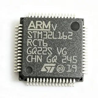
| 封装 | LQFP-64 |
| 工作温度范围 | -40C to +85C |
| ADC | 12-bit, 16 channels, with hardware oversampling |
| DAC | 12-bit, 2 channels |
| Comparators | 2 |
| LCD Driver | 8x40 segments |
| I2C Interfaces | 2 |
| SPI Interfaces | 2 |
| USART Interfaces | 2 |
| Low-Power UART | 1 |
| USB | USB 2.0 full-speed device |
| RNG | Hardware random number generator |
| RTC | True RTC with calendar and alarm |
| Standby Mode Current | 0.29 µA (with RTC) |
| Stop Mode Current | 3.4 µA (with RTC) |
| Low-Power Run Mode Current | 3.2 µA at 32 kHz |
| RoHS 状态 | Compliant |
STM32L083RBT6 引脚配置
| 引脚 1 | VBAT — Backup battery supply for RTC and backup registers |
| 引脚 2 | PC13 — GPIO / RTC tamper / RTC wakeup |
| 引脚 3 | PC14 — GPIO / OSC32_IN |
| 引脚 4 | PC15 — GPIO / OSC32_OUT |
| 引脚 5 | PF0 — GPIO / OSC_IN |
| 引脚 6 | PF1 — GPIO / OSC_OUT |
| 引脚 7 | NRST — Reset (active low) |
| 引脚 8 | VSSA — Analog ground |
| 引脚 9 | VDDA — Analog power supply |
| 引脚 10 | PA0 — GPIO / ADC_IN0 / WKUP1 |
| 引脚 11 | PA1 — GPIO / ADC_IN1 |
| 引脚 12 | PA2 — GPIO / ADC_IN2 / USART2_TX |
| 引脚 13 | PA3 — GPIO / ADC_IN3 / USART2_RX |
| 引脚 14 | PA4 — GPIO / ADC_IN4 / DAC_OUT1 |
| 引脚 15 | PA5 — GPIO / ADC_IN5 / DAC_OUT2 |
| 引脚 16 | PA6 — GPIO / ADC_IN6 / SPI1_MISO |
| 引脚 17 | PA7 — GPIO / ADC_IN7 / SPI1_MOSI |
| 引脚 18 | PB0 — GPIO / ADC_IN8 |
| 引脚 19 | PB1 — GPIO / ADC_IN9 |
| 引脚 20 | PB2 — GPIO / BOOT1 |
| 引脚 21 | PB10 — GPIO / I2C2_SCL / USART3_TX |
| 引脚 22 | PB11 — GPIO / I2C2_SDA / USART3_RX |
| 引脚 23 | PB12 — GPIO / SPI2_NSS / I2C2_SMBA |
| 引脚 24 | PB13 — GPIO / SPI2_SCK |
| 引脚 25 | PB14 — GPIO / SPI2_MISO |
| 引脚 26 | PB15 — GPIO / SPI2_MOSI |
| 引脚 27 | PC6 — GPIO / USART6_TX |
| 引脚 28 | PC7 — GPIO / USART6_RX |
| 引脚 29 | PC8 — GPIO / USART6_CK |
| 引脚 30 | PC9 — GPIO / USART6_CTS |
| 引脚 31 | PA8 — GPIO / MCO / USART1_CK |
| 引脚 32 | PA9 — GPIO / USART1_TX / USB_VBUS |
| 引脚 33 | PA10 — GPIO / USART1_RX / USB_DM |
| 引脚 34 | PA11 — GPIO / USB_DM / USART1_CTS |
| 引脚 35 | PA12 — GPIO / USB_DP / USART1_RTS |
| 引脚 36 | PA13 — GPIO / SWDIO |
| 引脚 37 | PA14 — GPIO / SWCLK |
| 引脚 38 | PA15 — GPIO / SPI1_NSS / JTDI |
| 引脚 39 | PB3 — GPIO / SPI1_SCK / JTDO |
| 引脚 40 | PB4 — GPIO / SPI1_MISO / NJTRST |
| 引脚 41 | PB5 — GPIO / SPI1_MOSI / I2C1_SMBA |
| 引脚 42 | PB6 — GPIO / I2C1_SCL / USART1_TX |
| 引脚 43 | PB7 — GPIO / I2C1_SDA / USART1_RX |
| 引脚 44 | BOOT0 — Boot mode selection |
| 引脚 45 | PB8 — GPIO / I2C1_SCL / CAN_RX |
| 引脚 46 | PB9 — GPIO / I2C1_SDA / CAN_TX |
| 引脚 47 | VSS — Ground |
| 引脚 48 | VDD — Power supply |
| 引脚 49 | PC10 — GPIO / USART4_TX |
| 引脚 50 | PC11 — GPIO / USART4_RX |
| 引脚 51 | PC12 — GPIO / USART5_TX |
| 引脚 52 | PD2 — GPIO / USART5_RX |
| 引脚 53 | PB13 — GPIO / SPI2_SCK |
| 引脚 54 | PB14 — GPIO / SPI2_MISO |
| 引脚 55 | PB15 — GPIO / SPI2_MOSI |
| 引脚 56 | PC13 — GPIO / RTC_TAMP1 |
| 引脚 57 | PC14 — GPIO / OSC32_IN |
| 引脚 58 | PC15 — GPIO / OSC32_OUT |
| 引脚 59 | PF0 — GPIO / OSC_IN |
| 引脚 60 | PF1 — GPIO / OSC_OUT |
| 引脚 61 | VSS — Ground |
| 引脚 62 | VDD — Power supply |
| 引脚 63 | VSS — Ground |
| 引脚 64 | VDD — Power supply |
典型应用
STM32L083RBT6 适用于 6 应用s: Smart Meters, Healthcare Devices, Industrial Sensors, IoT Nodes, Portable Instruments, Smart Home Devices.
Smart Meters
The STM32L083RBT6 is ideal for smart meters due to its ultra-low-power consumption, integrated LCD driver, and multiple communication interfaces. In a typical smart meter, the MCU reads sensor data, processes it, and displays it on an LCD while periodically transmitting data via a communication interface. The low-power modes allow the meter to operate for years on a single battery. The 12-bit ADC with hardware oversampling ensures accurate measurement of voltage and current, while the RTC provides precise timekeeping for billing purposes. The device's wide supply voltage range (1.8V to 3.6V) accommodates various battery configurations, and its robust peripheral set simplifies the design of a complete metering solution.
推荐
Healthcare Devices
The STM32L083RBT6 is well-suited for healthcare devices such as portable patient monitors, glucose meters, and pulse oximeters. Its ultra-low-power operation extends battery life, which is critical for wearable and portable medical devices. The integrated ADC and comparators enable accurate sensor signal conditioning, while the multiple communication interfaces allow data transfer to a smartphone or cloud. The device's small form factor and low power consumption make it ideal for continuous monitoring applications. The RTC ensures accurate time-stamping of medical data, and the hardware RNG can be used for secure data encryption, protecting patient privacy.
推荐
Industrial Sensors
The STM32L083RBT6 is an excellent choice for industrial sensors, such as temperature, pressure, and flow sensors. Its wide operating temperature range (-40C to +85C) and robust design make it suitable for harsh industrial environments. The device's low-power modes enable battery-powered wireless sensor nodes that can operate for years without maintenance. The 12-bit ADC with oversampling provides high-resolution measurements, and the multiple communication interfaces (I2C, SPI, USART) allow easy integration with various sensor modules. The integrated LCD driver can be used for local display of sensor readings, and the RTC enables time-stamped data logging.
推荐
IoT Nodes
The STM32L083RBT6 is a perfect fit for IoT nodes, which require low power consumption, wireless connectivity, and sensor interfacing. The device's ultra-low-power modes allow battery-powered IoT nodes to operate for extended periods, making them suitable for smart home, environmental monitoring, and asset tracking applications. The multiple communication interfaces support various wireless modules, such as LoRa, BLE, and Zigbee. The integrated ADC and comparators enable direct connection to analog sensors, while the hardware RNG provides secure communication. The device's small package and rich peripheral set make it a versatile choice for IoT edge devices.
推荐
Portable Instruments
The STM32L083RBT6 is ideal for portable instruments such as digital multimeters, handheld data loggers, and portable test equipment. Its low power consumption ensures long battery life, and the integrated LCD driver simplifies the display interface. The 12-bit ADC with oversampling provides accurate measurements, and the multiple communication interfaces allow data transfer to a PC or smartphone. The device's wide supply voltage range and low-power modes make it suitable for battery-powered operation. The RTC enables time-stamped data logging, and the hardware RNG can be used for secure data storage.
推荐
Smart Home Devices
The STM32L083RBT6 is well-suited for smart home devices such as smart thermostats, smart locks, and environmental monitors. Its ultra-low-power consumption allows battery-powered devices to operate for years, and the integrated LCD driver can be used for local display. The multiple communication interfaces support various wireless protocols, enabling integration with smart home hubs. The device's low-power modes are ideal for devices that spend most of their time in sleep mode, waking up only to respond to events. The hardware RNG provides secure communication, and the RTC enables scheduling and time-based automation.
推荐
推荐产品汇总
工程参考数据: STM32L083RBT6 ——对比、设计指导和合规信息。
选型指南
与替代料对比
| 参数 | 本产品 | STM32L083RBT6TR | STM32L082RBT6 | STM32L073RBT6 |
|---|---|---|---|---|
| Package | LQFP-64 | LQFP-64 | LQFP-64 | LQFP-64 |
| Brand | STMicroelectronics | STMicroelectronics | STMicroelectronics | STMicroelectronics |
| Core | ARM Cortex-M0+ | ARM Cortex-M0+ | ARM Cortex-M0+ | ARM Cortex-M0+ |
| Maximum Frequency | 32 MHz | 32 MHz | 32 MHz | 32 MHz |
| Flash Memory | 128 KB | 128 KB | 64 KB | 128 KB |
| SRAM | 20 KB | 20 KB | 8 KB | 20 KB |
| LCD Driver | Yes (8x40) | Yes (8x40) | Yes (8x40) | Yes (8x40) |
| Hardware RNG | Yes | Yes | No | No |
| True RTC | Yes | Yes | No | No |
关键差异点
- Integrated LCD driver supporting up to 8x40 segments (对比 STM32L071RBT6)
- Hardware random number generator (RNG) (对比 STM32L073RBT6)
- True RTC with calendar and alarm (对比 STM32L073RBT6)
设计说明
The STM32L083RBT6 operates from 1.8V to 3.6V. Use a low-dropout regulator (LDO) to provide a stable supply voltage. Decouple the VDD and VDDA pins with 100nF and 1uF capacitors placed close to the pins. For battery-powered applications, consider using the low-power modes (Standby, Stop) to minimize current consumption. The VBAT pin can be connected to a backup battery to maintain RTC and backup registers when the main supply is removed.
For the LQFP-64 package, ensure proper PCB layout with a solid ground plane. Place decoupling capacitors (100nF) as close as possible to each VDD/VSS pair. For the ADC, provide a clean analog ground (VSSA) and analog supply (VDDA) with a ferrite bead to isolate from digital noise. The crystal oscillator pins (OSC_IN/OSC_OUT) should have short traces and proper load capacitors. Follow the layout guidelines in the STM32L0 reference manual (RM0367) for best performance.
Ensure the BOOT0 pin is properly configured to select the correct boot mode. For normal operation, BOOT0 should be tied low. The NRST pin should have a 100nF capacitor to ground for reliable reset. When using the USB interface, ensure the VBUS pin is connected to the USB power and the USB_DP/USB_DM traces are impedance-matched (90 ohms differential). Avoid floating GPIO pins by configuring them as outputs or enabling pull-ups/pull-downs to reduce leakage current.
合规信息
RoHS compliant per STMicroelectronics product page. Not AEC-Q100 qualified - choose STM32L083RBT6Q for automotive.