The PIC16F628A-I/SO is an 8-bit CMOS Flash microcontroller from Microchip Technology that runs at up to 20 MHz (200 ns instruction cycle) and integrates 3.5 KB (2K x 14) of Flash program memory, 224 bytes of RAM, 128 bytes of EEPROM, 16 digital I/O pins, a USART, a capture/compare/PWM module, and two analog comparators with a programmable voltage reference, all in an 18-pin SOIC (7.50 mm) surface-mount package. It operates from a 4.5 V to 5.5 V supply across the industrial -40 °C to +85 °C temperature range, includes a calibrated 4 MHz internal oscillator and brown-out reset, and supports ICSP in-circuit programming. The part is in active production and currently in stock at XAIPART with 99,999 units available, MOQ 1, priced from $3.50 at qty 1 down to $2.32 at qty 1000 as of 2026-09-23.
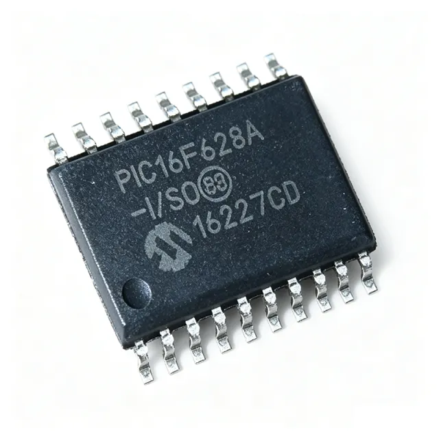
What Is the PIC16F628A-I/SO and Why Do Engineers Keep Specifying It?
The PIC16F628A-I/SO belongs to Microchip's PIC16 enhanced mid-range family. It executes a 35-instruction RISC set with a 14-bit Harvard instruction word, so the CPU prefetches the next instruction while completing the current one, and it features an eight-level hardware stack. The 'F' suffix indicates Flash program memory, which enables in-circuit serial programming (ICSP) for prototyping and field updates. The 'I' suffix designates the -40 °C to +85 °C industrial grade; 'SO' denotes the 18-pin 7.50 mm SOIC plastic package.
Three features differentiate this part in cost-sensitive designs. First, the nanoWatt power management with multiple idle/sleep modes drops supply current to the low-microamp range, which matters for battery-powered nodes. Second, the calibrated 4 MHz internal oscillator is accurate enough for UART baud-rate generation without an external crystal, removing timing components from the BOM. Third, the two analog comparators with a shared programmable voltage reference implement window-comparator signal conditioning without external op-amps.
Takeaway: If your design fits in 3.5 KB of code, needs a UART, runs on a 5 V rail, and must be cheap to build, this MCU covers it in a single SOIC-18 footprint.
How Do You Select and Design In the PIC16F628A-I/SO?
Design-in is straightforward if you respect the verified electrical envelope and a few layout practices:
- Power: Supply 4.5 V to 5.5 V on VDD (pin 14). Place a 0.1 µF decoupling capacitor within about 5 mm of VDD and another near VSS. The on-chip brown-out reset holds the MCU in reset when VDD falls below the operating threshold, protecting code integrity during supply sag.
- Clock: Use the calibrated 4 MHz internal oscillator for UART-based designs, or drive up to 20 MHz externally via OSC1/CLKIN (pin 16) for a 200 ns instruction cycle. Verify UART baud-rate error against your chosen BAUD value before committing to asynchronous links.
- Programming: Reserve RB6/ICSPCLK (pin 12) and RB7/ICSPDAT (pin 13) for the ICSP header. A 5-pin header on VDD, VSS, MCLR (pin 4), RB6, and RB7 lets you re-flash the assembled PCB with MPLAB X and a PICkit programmer. Avoid toggling MCLR while programming.
- Analog: Keep comparator input traces (RA0/RA1 on pins 17/18, RA2/RA3 on pins 1/2) short. The programmable voltage reference is shared with the comparators, so budget reference usage across both channels.
- I/O budgeting: Of the 16 I/O pins, RB6/RB7 double as ICSP, and RB0/INT (pin 6) is your best external interrupt input.
Takeaway: Route the ICSP header and decoupling into your first PCB revision; both cost almost nothing and save rework later.
What Are the Key Pins of the PIC16F628A-I/SO?
The functionally critical pins for most designs are power, reset, oscillator, USART, CCP, interrupt, and ICSP pins, listed below. The full 18-pin table lives on the PIC16F628A-I/SO product page.
Takeaway: Treat RB6/RB7 as programming-reserved in every layout, even if your firmware uses them as I/O after boot.
Where Does the PIC16F628A-I/SO Fit Best? Seven Verified Application Scenarios
Verified application data from the XAIPART database maps this MCU to seven scenario families:
- White-goods and appliance control: The 16 I/O pins drive relay triacs, seven-segment displays, and keypads; the 20 MHz core executes closed-loop control at sub-millisecond intervals. Comparators implement zero-crossing detection and water-level sensing.
- Automotive body and convenience modules: Interior lighting, central locking, and aftermarket alarms use the -40 °C to +85 °C range and brown-out reset for cranking sag. Note: this is industrial-grade, not AEC-Q100; validate automotive-grade PIC16F equivalents for those programs.
- Security and access-control panels: 128 bytes of EEPROM store credentials, comparators sense PIR amplifier outputs, and the USART links to GSM or Wi-Fi reporting modules.
- Battery-powered sensor nodes: nanoWatt sleep and the internal oscillator eliminate crystal warm-up latency; timers with capture registers measure flow-meter and ultrasonic pulse widths.
- Industrial sensor interfaces: Comparators build window detectors for 4-20 mA loops; the USART bridges to Modbus RTU via RS-485 transceivers.
- Consumer audio and IR remote controllers: The 20 MHz CPU generates precise IR carriers, and PWM produces 38 kHz subcarriers without external timers.
- Hobby and educational kits: The 35-instruction set is teachable in one lab session; ICSP supports iterative re-flashing on the board.
Takeaway: Match the scenario to the peripheral you actually need — UART, PWM, or comparators — and you will rarely need an external analog IC with this part.
What Are the Drop-In Alternatives to the PIC16F628A-I/SO?
Per Microchip's cross-reference data cited in the verified database, the best drop-in replacements come from the same PIC16F62x family in the SOIC-18 footprint:
- PIC16F627A-I/SO: Pin-to-pin compatible with half the Flash (1.75 KB / 1K x 14) but the same peripherals, RAM, and EEPROM. Choose it for lowest cost when code fits.
- PIC16F648A-I/SO: Pin-to-pin compatible with double the Flash (8 KB) and 256 bytes of RAM. Choose it when your code base outgrows 3.5 KB or needs larger buffers.
- PIC16F628-04I/SO: Drops into the same footprint at 4 MHz for lowest cost without redesign.
- PIC16F628A-I/P: Identical silicon, memory, peripherals, and pinout in a through-hole 18-pin PDIP package — ideal for breadboarding, with firmware fully portable to the SO part.
| Parameter | PIC16F628A-I/SO | PIC16F627A-I/SO | PIC16F648A-I/SO | PIC16F628A-I/P |
|---|---|---|---|---|
| Package | 18-SOIC (7.50 mm), SMD | SOIC-18 (pin-compatible) | SOIC-18 (pin-compatible) | 18-PDIP, through-hole |
| Flash program memory | 3.5 KB (2K x 14) | 1.75 KB (1K x 14) | 8 KB | 3.5 KB (2K x 14) |
| RAM | 224 bytes | Same as 628A per family cross-reference | 256 bytes | 224 bytes |
| Peripherals / pinout | USART, PWM, 2 comparators, 16 I/O | Identical footprint and peripherals | Identical footprint and peripherals | Identical silicon and pinout |
| Best use | Standard mid-range choice | Lowest cost, smaller code | Headroom for larger firmware | Prototyping / breadboard |
Verified pricing for the PIC16F628A-I/SO at XAIPART as of 2026-09-23: $3.50 (qty 1), $3.15 (qty 10), $2.80 (qty 100), $2.55 (qty 500), $2.32 (qty 1000). Comparable-tier pricing for the 627A, 648A, and PDIP variants is not in the verified dataset; request quotes on the XAIPART component catalog before finalizing a BOM decision.
Takeaway: Design your footprint and firmware within the PIC16F62x SOIC-18 family and you keep a cost/memory trade path without any PCB respin.
A Practical Design: 5 V Appliance Controller with UART Diagnostics
Problem: An appliance UI board needs relay control, keypad scanning, a seven-segment display, zero-crossing detection, and a serial diagnostic link — on a 5 V rail, at minimum BOM cost.
Approach: Use the PIC16F628A-I/SO as the sole controller. Drive loads from I/O pins, use one comparator with the programmable voltage reference for AC zero-crossing detection, and connect the USART (RB1/RX pin 7, RB2/TX pin 8) to an external RS-232/RS-485 transceiver for diagnostics. Run on the calibrated 4 MHz internal oscillator to eliminate the crystal.
Design notes: Reserve RB6/RB7 for ICSP. Place a 0.1 µF capacitor at VDD and another at VSS. Pull MCLR (pin 4) appropriately for normal run. Verify UART baud-rate error at the 4 MHz internal clock against your BAUD setting before release.
Results: One 18-pin MCU covers control, analog sensing, and serial communication with no external timing or amplifier ICs, on a verified 4.5 V-5.5 V, -40 °C to +85 °C operating envelope.
What Is the Market Position, Lifecycle, and Supply Situation of the PIC16F628A-I/SO?
The verified lifecycle status is active — the part is in active production. XAIPART lists 99,999 units in stock with MOQ 1 and tiered pricing down to $2.32 at qty 1000 as of 2026-09-23, supporting both prototype buys and volume SMD production. Verified distributor availability data indicates same-day shipment for quantities under 1000, with reel-pack (TR) variants for production lines; for very large orders, 4-6 weeks of manufacturer lead time may apply during allocation events. No formal end-of-life or last-time-buy notice exists in the verified dataset.
Takeaway: With active lifecycle status and six-figure stock on hand, this is a safe part to design in today; still, lock in a second source path within the PIC16F62x family for long-life programs.
What Should Buyers Watch Next for the PIC16F628A-I/SO?
Watch three things, all anchored to verified specs. First, memory ceiling: at 3.5 KB Flash and 224 bytes of RAM, firmware creep is the most common reason to move — the pin-compatible PIC16F648A-I/SO (8 KB Flash, 256 B RAM) is the migration path without a respin. Second, packaging economics: at $2.32 at qty 1000 as of 2026-09-23, the SOIC-18 part is priced for volume; MSL 1 rating means no dry-cabinet handling on your SMD line. Third, qualification boundaries: this is an industrial-grade (not AEC-Q100) part, so automotive programs must move to Microchip's automotive-grade PIC16F equivalents. Buyers tracking broader silicon sourcing trends can also compare notes in our other XAIPART design guides, including the Intel MAX II CPLD guide and the BTS462TATMA1 smart power switch guide.
Takeaway: Buy to your code-size headroom, not your current binary size — the family's pin compatibility makes upgrading a line-item change, not a redesign.
Comments
Be the first to comment.
🔐 Please sign in to post a comment.
Don't have an account? Sign up