RF & Wireless
ژێرپۆلەکان
بەرهەمەکان (730+)

ADL5385ACPZ-R7 - 50MHz-2.2GHz Quadrature Modulator | Analog Devices
The ADL5385ACPZ-R7 is a silicon, monolithic, quadrature modulator designed for use from 30 MHz to 2200 MHz. It is housed in a 24-lead LFCSP (WFQFN) package with an exposed pad, and is supplied in tape and reel packaging. This device provides excellent phase accuracy and amplitude balance, enabling high performance intermediate frequency (IF) and direct radio frequency (RF) modulation for communication systems. A quadrature modulator is a key building block in modern wireless transmitters. It takes two baseband signals (I and Q) and modulates them onto a carrier signal, producing a modulated RF output. This architecture is fundamental to digital communication standards such as WCDMA, LTE, and WiMAX, where complex modulation schemes require precise I/Q balance. The ADL5385 simplifies the design of such transmitters by integrating the modulator function into a single IC, reducing component count and board space. Key features of the ADL5385 include a wide operating frequency range from 30 MHz to 2200 MHz, excellent phase accuracy and amplitude balance, and a differential baseband interface. The device operates from a single 5V supply and provides a high output IP3, making it suitable for demanding linearity requirements. The LFCSP package with exposed pad ensures efficient thermal dissipation, while the tape and reel packaging (R7 suffix) is optimized for high-volume production. Technically, the ADL5385 uses a double-balanced mixer topology with integrated quadrature phase splitting. This architecture provides high carrier feedthrough suppression and excellent sideband suppression, which are critical for spectral purity. The device also features a wide baseband bandwidth, allowing it to support both narrowband and wideband modulation schemes. Its performance is specified over the full -40°C to +85°C temperature range, ensuring reliable operation in diverse environments. Typical applications include cellular base stations, point-to-point radios, satellite communications, and test and measurement equipment. In these systems, the ADL5385 is used to upconvert baseband I/Q signals to RF frequencies, enabling efficient and accurate signal transmission. Its high linearity and low noise make it ideal for high-performance communication links. When designing with the ADL5385, it is important to provide proper decoupling on the supply pins and to match the differential baseband inputs to the driving source impedance. The exposed pad should be soldered to a ground plane for optimal thermal and electrical performance. Additionally, the LO input should be driven with a clean, well-leveled signal to achieve the best carrier feedthrough performance.

ADL5545 - 24dB RF/IF Gain Block 30MHz-6GHz | Analog Devices
The ADL5545 is a single-ended RF/IF gain block amplifier from Analog Devices, offering broadband operation from 30 MHz to 6 GHz. It provides a fixed gain of 24.1 dB, which is stable over frequency, temperature, power supply, and device-to-device variations. The amplifier is offered in the industry-standard SOT-89 package and is internally matched to 50 Ω at the input and output, simplifying implementation in a wide variety of applications. The only external components required are input/output AC coupling capacitors and a bias inductor, making the ADL5545 easy to integrate into RF signal chains. An RF gain block is a type of amplifier used to boost signal power in radio frequency systems, typically placed between stages to compensate for insertion losses. It is a fundamental building block in RF front-ends, often following a mixer or filter and preceding a power amplifier or antenna. Gain blocks are characterized by parameters such as gain, bandwidth, output third-order intercept point (OIP3), noise figure, and supply current. The ADL5545 belongs to the category of broadband gain blocks, which are essential in applications requiring flat gain across a wide frequency range. Key features of the ADL5545 include a fixed gain of 24.1 dB, an OIP3 of over 36 dBm, and a supply current of only 56 mA from a 5 V supply. The device operates over a frequency range of 30 MHz to 6 GHz, covering many communication bands including cellular, ISM, and Wi-Fi. The SOT-89 package is a standard surface-mount package with a thermal pad, allowing for efficient heat dissipation. The amplifier is internally matched to 50 Ω, eliminating the need for external matching networks and reducing component count. Technically, the ADL5545 uses a Darlington-pair topology with active bias, providing high linearity and stable performance over temperature and supply variations. The active bias circuit ensures consistent operating point, which contributes to the gain stability. The device is designed to operate from a single 5 V supply, with a typical supply current of 56 mA, resulting in a power dissipation of approximately 280 mW. The SOT-89 package has a thermal resistance of about 50°C/W, so adequate PCB copper area is recommended for thermal management. Typical applications for the ADL5545 include cellular base station transceivers, wireless infrastructure, test and measurement equipment, and general-purpose RF amplification. Its wide bandwidth and high linearity make it suitable for both transmit and receive paths. In a typical application, the ADL5545 is placed after a mixer to amplify the IF signal or before a power amplifier to drive it to the required level. When designing with the ADL5545, it is important to provide proper AC coupling at the input and output, as the device is internally biased. A bias inductor is required on the output to supply DC power while blocking RF. The ground pad should be soldered to a low-inductance ground plane to ensure thermal and electrical performance. The device is rated for operation over the temperature range of -40°C to +85°C, making it suitable for industrial applications.

ADL8124 - 1-20GHz LNA with Temp Sensor | Analog Devices
The ADL8124 is a highly integrated, dual-channel low noise amplifier (LNA) from Analog Devices, designed for applications operating in the 1GHz to 20GHz frequency range. It is fabricated using advanced GaAs pHEMT technology, delivering a low 2.1dB (typical) noise figure and a typical gain of 15dB across a wide bandwidth. The device operates from a 3.3V supply with a quiescent current of 55mA, and includes on-chip input and output AC coupling capacitors, an integrated bias inductor, an integrated temperature sensor, and an enable/disable pin (VENBL). The ADL8124 is available in a compact 8-lead LFCSP (2x2mm) package, making it suitable for space-constrained RF front-end designs. A low noise amplifier (LNA) is a critical component in RF and microwave receiver chains, placed at the front end to amplify weak signals while adding minimal noise. The LNA's noise figure directly affects the overall system sensitivity, and its gain helps overcome the noise of subsequent stages. In the hierarchy of RF signal chains, the LNA is part of the receiver front-end, which includes filters, mixers, and analog-to-digital converters. The ADL8124's integrated features reduce external component count and simplify PCB design, making it an attractive choice for high-frequency communication systems. Key features of the ADL8124 include its wide frequency coverage from 1GHz to 20GHz, which spans multiple communication bands including 5G, radar, and satellite communications. The integrated temperature sensor allows for real-time monitoring of the device's thermal state, enabling adaptive bias control or system-level thermal management. The enable/disable pin (VENBL) provides flexible power management, allowing the LNA to be shut down when not in use to save power. The on-chip AC coupling capacitors and bias inductor eliminate the need for external matching components, simplifying the design and reducing board space. Technically, the ADL8124 is designed using GaAs pHEMT technology, which offers excellent high-frequency performance with low noise and high gain. The device is specified at VDD = 3.3V, IDQ = 55mA, with a bias resistance (RBIAS) of 1540Ω and VENBL = 3.3V. The typical noise figure of 2.1dB and gain of 15dB are achieved across the entire 1-20GHz band, making it a versatile solution for various RF applications. The integrated temperature sensor provides a voltage output proportional to temperature, which can be read by an ADC for monitoring purposes. Typical applications for the ADL8124 include 5G base stations, radar systems, satellite communications, point-to-point radios, and test and measurement equipment. Its wide bandwidth and low noise figure make it ideal for receiver front-ends in these systems, where signal integrity is paramount. The compact LFCSP package and integrated features allow for dense PCB layouts, which is essential in modern RF modules. When designing with the ADL8124, it is important to ensure proper thermal management, as the device dissipates power during operation. The enable pin can be used to power down the LNA when not in use, reducing overall system power consumption. Additionally, the bias resistor (RBIAS) should be selected according to the datasheet recommendations to achieve the desired quiescent current and performance.
ADL8124ACPZ - 1-20GHz LNA with Temp Sensor | Analog Devices
The ADL8124ACPZ is a highly integrated, 1GHz to 20GHz low noise amplifier (LNA) from Analog Devices, designed for general-purpose RF and microwave applications. It operates from a 3.3V supply with a quiescent current of 55mA, and features on-chip input and output AC coupling capacitors, an integrated bias inductor, an integrated temperature sensor, and an enable/disable pin (VENBL). The device is housed in a compact 8-lead LFCSP (2x2 mm) package, making it ideal for space-constrained designs. A low noise amplifier (LNA) is a critical building block in RF receivers, placed at the front end to amplify weak signals while adding minimal noise. The ADL8124 belongs to the class of wideband LNAs, covering 1GHz to 20GHz, which spans multiple communication bands including 5G, satellite, and radar. Its integrated bias inductor and AC coupling capacitors reduce external component count, simplifying PCB design and improving reliability. Key features include a wide frequency range of 1GHz to 20GHz, low noise figure, and high gain, making it suitable for various RF front-end applications. The integrated temperature sensor provides real-time monitoring for thermal management, and the enable pin allows power gating for duty-cycled systems. The device operates from a single 3.3V supply, with a typical quiescent current of 55mA, and includes an exposed pad for thermal and electrical grounding. The ADL8124 uses a GaAs or SiGe process (exact process not specified in available data) to achieve high-frequency performance. The integrated bias inductor and AC coupling capacitors are designed to minimize external components, while the temperature sensor and enable pin add functionality without compromising RF performance. The package ground leads and exposed pad connect directly to the ground plane, with multiple vias recommended for adequate electrical and thermal conduction. Typical applications include 5G base stations, satellite communications, radar systems, and test and measurement equipment. The wide frequency range and low noise figure make it suitable for both narrowband and wideband receivers. The integrated temperature sensor is particularly useful in high-reliability systems where thermal monitoring is critical. When designing with the ADL8124, ensure proper grounding of the exposed pad and use multiple vias to the ground plane for optimal thermal and electrical performance. The enable pin can be used for power sequencing or duty-cycling to reduce average power consumption.

ADMV1013S-CSL - 24-44GHz Upconverter | Analog Devices
The ADMV1013S-CSL is a wideband, microwave upconverter from Analog Devices, designed for point-to-point microwave radio systems operating in the 24 GHz to 44 GHz frequency range. It comes in a compact, thermally enhanced 40-terminal land grid array (LGA) package and operates over a case temperature range of -40°C to +85°C. This device is part of the Commercial Space Products Program, offering enhanced reliability for space and high-reliability applications. A microwave upconverter is a critical component in RF transmitters that translates a lower intermediate frequency (IF) signal to a higher radio frequency (RF) for transmission. In the hierarchy of RF signal chains, the upconverter sits between the baseband/modem and the power amplifier, converting the modulated IF signal to the desired RF band. The ADMV1013S-CSL supports two modes of frequency translation, providing flexibility in system architecture. Key features include wideband operation from 24 GHz to 44 GHz, which covers multiple microwave bands including K and Ka bands. The device offers high linearity and low conversion loss, essential for maintaining signal integrity in high-order modulation schemes. The LGA package provides excellent thermal performance, enabling reliable operation in demanding environments. The -40°C to +85°C case temperature range ensures suitability for both commercial and space-grade applications. Technically, the ADMV1013S-CSL integrates a double-balanced mixer, local oscillator (LO) buffer, and RF amplifier in a single package. This integration reduces external component count and simplifies board design. The device is optimized for point-to-point microwave links, where frequency stability and phase noise are critical. The upconverter's wideband nature allows it to be used across multiple frequency plans without redesign. Typical applications include 5G mmWave infrastructure, satellite communications, radar systems, and test and measurement equipment. In 5G base stations, the ADMV1013S-CSL can upconvert IF signals to the 24-44 GHz band for massive MIMO and beamforming arrays. For satellite ground terminals, it provides reliable frequency conversion for Ka-band links. When designing with this device, ensure proper impedance matching at all ports and provide adequate grounding for the LGA package. The thermal pad should be connected to a solid ground plane with thermal vias to maximize heat dissipation. Also, consider the LO drive level and isolation to prevent spurious emissions.

ADMV4821 - 24-29.5GHz 5G Beamformer | Analog Devices
The ADMV4821 is a highly integrated silicon germanium (SiGe) beamformer from Analog Devices, operating over the 24 GHz to 29.5 GHz frequency range. It addresses the n257, n258, and n261 5G NR bands in a single footprint, supporting 16 selectable transmit (TX) and 16 selectable receive (RX) channels. The device provides both horizontal and vertical polarization through independent RFV and RFH common pins, enabling dual-polarized antenna arrays. It is packaged in a compact LGA package that allows top-side heatsinking for efficient thermal management and flexible antenna placement on the opposite side of the PCB. A beamformer is a key component in phased-array antenna systems, responsible for adjusting the phase and amplitude of signals to steer the antenna beam electronically without moving parts. In 5G mmWave base stations, beamformers enable massive MIMO (Multiple-Input Multiple-Output) configurations, improving spectral efficiency and coverage. The ADMV4821 integrates 16 channels, each with independent phase and gain control, into a single IC, significantly reducing the size and complexity of the RF front-end compared to discrete implementations. Key features include a wide operating frequency range covering multiple 5G bands, 16 TX and 16 RX channels, dual polarization support, and a serial peripheral interface (SPI) for control. The device operates over a -40°C to +95°C case temperature range, making it suitable for outdoor base station environments. The LGA package with top-side heatsinking allows for efficient heat dissipation, crucial for high-power beamforming applications. The ADMV4821 uses a SiGe process technology, offering a good balance of performance and integration for mmWave frequencies. The SPI interface enables precise control of phase and gain settings, with a protocol consisting of a read/write bit, 15 register address bits, and 8 data bits. The device includes internal LDO regulators, allowing it to be powered from a single supply, simplifying power supply design. Typical applications include 5G NR base stations, phased-array antennas, satellite communications, and radar systems. In 5G base stations, the ADMV4821 is used in the active antenna unit to form and steer beams, improving signal quality and capacity. Its dual-polarization capability supports polarization diversity, enhancing link reliability. When designing with the ADMV4821, careful attention must be paid to thermal management, as the device can dissipate significant power. The LGA package's top-side heatsinking should be utilized with an appropriate heatsink or thermal interface material. Additionally, the SPI interface should be properly terminated and decoupled to ensure reliable control.
ADMV4821-EVAL - 24-29.5GHz 5G Beamformer Eval Board | Analog Devices
The ADMV4821-EVAL is an evaluation board from Analog Devices designed to evaluate the ADMV4821, a silicon germanium (SiGe), 24 GHz to 29.5 GHz, dual-polarization 5G beamformer. The board integrates the ADMV4821 with low dropout (LDO) regulators, level shifters, and an EVAL-SDP-CS1Z (SDP-S) controller board, enabling simplified and efficient evaluation of the beamformer's 16 transmit and 16 receive channels. The ADMV4821 supports the n257, n258, and n261 5G NR bands in a single footprint, with matched 50-ohm single-ended RF inputs and outputs for both horizontal and vertical polarizations. A beamformer is a highly integrated RF front-end component that electronically steers antenna beams by adjusting the phase and amplitude of signals across multiple antenna elements. In massive MIMO systems, beamformers like the ADMV4821 are essential for achieving the high data rates and spectral efficiency required by 5G networks. The ADMV4821 belongs to the class of millimeter-wave (mmW) beamformer ICs, which are part of the broader category of RF front-end modules used in base stations and user equipment. Key features of the ADMV4821 include 16 selectable TX channels and 16 selectable RX channels, dual polarization support, and a frequency range covering 24 GHz to 29.5 GHz. The evaluation board simplifies testing by providing all necessary power regulation and control interfaces, allowing engineers to focus on RF performance validation. The board is designed for use with the SDP-S controller, which provides a USB interface for software control of the beamformer's settings. The ADMV4821 is fabricated in a SiGe process, offering a good balance of performance and integration for mmW applications. The device includes on-chip LDO regulators to ensure clean power delivery to the RF circuitry, reducing external component count. The evaluation board's layout is optimized for 50-ohm impedance matching, ensuring accurate measurements of gain, phase, and beamforming performance. Typical applications for the ADMV4821-EVAL include 5G NR base station development, phased array antenna prototyping, and beamforming algorithm validation. The board is also useful for evaluating the ADMV4821 in test and measurement setups, where its wide frequency coverage and dual-polarization capability are advantageous. When using the ADMV4821-EVAL, ensure proper power sequencing and control via the SDP-S board. The evaluation board requires a 5V supply and a USB connection to the controller. For accurate RF measurements, use calibrated test equipment and follow the guidelines in the user guide UG-1564.
ADMV4821B - 24-29.5GHz Dual-Pol Beamformer | Analog Devices
The ADMV4821B is a dual-polarization beamformer from Analog Devices, operating over the 24 GHz to 29.5 GHz frequency range, covering the n257, n258, and n261 5G NR bands in a single footprint. It integrates 16 selectable transmit (TX) channels and 16 selectable receive (RX) channels, supporting horizontal and vertical polarization with matched 50-ohm single-ended RF inputs and outputs. This device is designed for phased-array antenna systems in 5G base stations and satellite communications, offering high integration to simplify beamforming architectures. A beamformer is a key component in phased-array systems that electronically steers the antenna beam by adjusting the phase and amplitude of signals across multiple antenna elements. The ADMV4821B belongs to the class of RF beamforming ICs, which are essential in modern 5G NR and radar systems. By integrating multiple channels and dual polarization, it reduces the component count and PCB area compared to discrete implementations, enabling compact and cost-effective antenna modules. Key features include a wide RF frequency range of 24 GHz to 29.5 GHz, 16 TX and 16 RX channels, dual polarization support, and matched 50-ohm single-ended interfaces. The device is recommended for new designs, indicating active lifecycle status. It is packaged in a compact BCCZ package, suitable for surface-mount assembly, and is designed to meet the stringent performance requirements of 5G infrastructure. Technically, the ADMV4821B integrates phase shifters, gain amplifiers, and T/R switches on a single die, providing precise beam control. The dual-polarization capability allows simultaneous transmission and reception on both horizontal and vertical polarizations, doubling the data throughput in MIMO systems. The device is controlled via a serial interface, enabling fast beam steering and calibration. Typical applications include 5G NR base stations, phased-array antennas, satellite communications, and radar systems. Its wide frequency coverage and dual-polarization support make it ideal for massive MIMO and beamforming networks. The device's high integration reduces system complexity and power consumption, making it suitable for dense antenna arrays. When designing with the ADMV4821B, careful attention must be paid to thermal management and RF layout. The device's thermal resistance values are simulated based on JEDEC specifications (JESD51-12), so proper PCB design with adequate ground vias and heat sinking is critical. Additionally, the RF inputs and outputs are single-ended 50-ohm, requiring proper impedance matching to minimize reflections.
ADMV4821C - 24-29.5GHz Dual-Pol Beamformer | Analog Devices
The ADMV4821C is a dual-polarization beamformer from Analog Devices, operating from 24 GHz to 29.5 GHz, covering the n257, n258, and n261 5G NR bands in a single footprint. It integrates 16 selectable TX channels and 16 selectable RX channels, supporting both horizontal and vertical polarization. The device features matched 50-ohm single-ended RF inputs and outputs, simplifying system integration. It is recommended for new designs and is available in a compact BCCZ package, suitable for phased-array antenna systems. A beamformer is a key component in phased-array antenna systems, responsible for controlling the phase and amplitude of signals to steer the antenna beam electronically. It is part of the RF front-end chain, which includes antennas, transceivers, and beamformers. The ADMV4821C is a dual-polarization beamformer, meaning it can handle both horizontal and vertical polarizations simultaneously, effectively doubling the data throughput in MIMO systems. This makes it ideal for 5G base stations and satellite communications. Key features include a wide RF frequency range of 24 GHz to 29.5 GHz, 16 TX and 16 RX channels, dual-polarization support, and matched 50-ohm single-ended interfaces. The device is designed for high linearity and low noise figure, ensuring excellent signal quality. It also offers flexible control interfaces for beam steering, making it suitable for advanced antenna arrays. Technically, the ADMV4821C integrates multiple RF chains with phase shifters and gain amplifiers, all controlled via a serial interface. The dual-polarization architecture allows for 2x2 MIMO operation, enhancing spectral efficiency. The device operates from a single supply voltage and includes on-chip temperature compensation for stable performance across temperature. Typical applications include 5G NR base stations, satellite ground terminals, radar systems, and point-to-point communication links. The wide frequency coverage and dual-polarization capability make it a versatile solution for emerging mmWave applications. When designing with the ADMV4821C, careful attention must be paid to thermal management and RF layout. The device dissipates significant power, and proper heat sinking is essential. Additionally, the RF traces should be impedance-matched to 50 ohms to minimize reflections.
ADPA1112 - 1-22GHz 15W GaN PA | Analog Devices
The ADPA1112 is a wideband Gallium Nitride (GaN) power amplifier from Analog Devices, covering 1 GHz to 22 GHz with a saturated output power (POUT) of 42 dBm (approximately 15 W). It delivers a power added efficiency (PAE) of 25% and a power gain of 14 dB typical from 8 GHz to 16 GHz at an input power (PIN) of 28.0 dBm. The device is housed in a 14-lead LDCC (9.8x8.2 mm) package, suitable for surface mount assembly. A GaN power amplifier is a high-electron-mobility transistor (HEMT) based amplifier that leverages the wide bandgap of gallium nitride to achieve high power density, high efficiency, and wide bandwidth. In the hierarchy of RF power amplification, GaN PAs sit above silicon LDMOS and GaAs in terms of power handling and frequency range, making them essential for modern radar, electronic warfare, and broadband communication systems. The ADPA1112 is designed for general-purpose amplification across multiple bands, offering a single solution for systems that need to operate from 1 GHz to 22 GHz. Key features include a saturated output power of 42 dBm, PAE of 25%, and a power gain of 14 dB. The wide frequency range of 1 GHz to 22 GHz allows it to cover L, S, C, X, Ku, and K bands, reducing the need for multiple narrowband amplifiers. The device is recommended for new designs, indicating active lifecycle status. It operates from a drain supply voltage, with typical quiescent current and thermal performance specified in the datasheet. Technically, the ADPA1112 uses a GaN-on-SiC process, which provides excellent thermal conductivity and high breakdown voltage, enabling high output power with reliability. The amplifier is internally matched to 50 ohms, simplifying system integration. It requires external bias circuitry and proper thermal management to dissipate heat generated at high output power levels. Typical applications include radar systems, electronic warfare (EW) jammers, satellite communications (SATCOM), and test and measurement equipment. Its wideband nature makes it ideal for software-defined radio (SDR) transmitters and multi-band communication systems where a single PA can cover multiple frequency bands. When designing with the ADPA1112, ensure adequate heat sinking and consider the thermal resistance of the package. The device requires a stable drain supply and proper RF decoupling. The input and output are matched to 50 ohms, but external matching may be needed for optimal performance at the band edges.
ADPA1113 - 2-6GHz 46dBm GaN Power Amplifier | Analog Devices
The ADPA1113 is a gallium nitride (GaN) broadband power amplifier from Analog Devices, delivering 46.5 dBm (44.7 W) output power with 39.0% power added efficiency (PAE) across the 2.3 GHz to 5.7 GHz frequency range. Housed in a 14-lead LDCC (9.8x8.2 mm) package, this device operates from a nominal 28 V drain supply with an externally applied negative gate voltage on the VGG1 pin to set the total quiescent current (IDQ) to 750 mA. The amplifier features cascaded gain stages and requires no external matching, AC coupling, or external inductor for biasing, simplifying system design and reducing bill of materials. A GaN power amplifier is a high-efficiency RF amplifier that uses gallium nitride transistors to achieve high output power and wide bandwidth. GaN technology offers superior power density, thermal performance, and efficiency compared to traditional silicon-based amplifiers, making it ideal for demanding RF applications. In the signal chain hierarchy, the ADPA1113 functions as a final-stage power amplifier, converting low-level RF signals into high-power signals suitable for transmission, typically following driver amplifiers and preceding antennas or filters. Key features of the ADPA1113 include its 46.5 dBm saturated output power, 39.0% PAE, and operation across the full 2.3 GHz to 5.7 GHz band without external matching. The device is biased with a positive 28 V drain supply and a negative gate voltage, enabling precise control of the quiescent current. The 14-lead LDCC package provides excellent thermal performance, with the exposed pad facilitating heat transfer to the PCB. The amplifier is recommended for new designs, indicating active lifecycle status and ongoing manufacturer support. Technically, the ADPA1113 utilizes a cascaded gain stage architecture, allowing it to achieve high gain and output power in a single device. The negative gate bias (VGG1) sets the operating point, ensuring linearity and efficiency across the frequency range. The device's broadband performance eliminates the need for external matching networks, reducing design complexity and component count. The 28 V drain supply is typical for GaN devices, balancing efficiency and output power. Typical applications include radar systems, electronic warfare, communications infrastructure, and test and measurement equipment. The ADPA1113's high output power and wide bandwidth make it suitable for pulsed and continuous-wave (CW) operation in these systems. Its efficiency reduces thermal management requirements, enabling compact system designs. When designing with the ADPA1113, ensure proper thermal management through adequate PCB copper area and heat sinking, as the device dissipates significant power at high output levels. The negative gate bias must be applied before the drain supply to prevent device damage, following standard GaN biasing sequences.
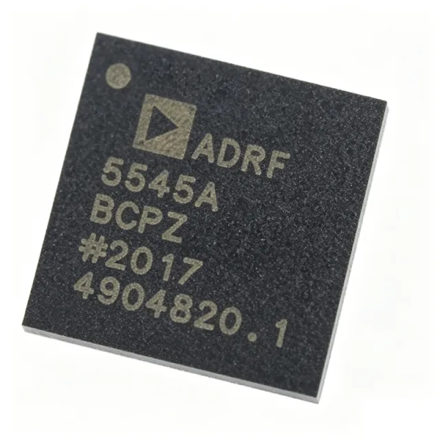
ADRF5545ABCPZN - Dual-Channel 2.4-4.2GHz RF Front End | Analog Devices
The ADRF5545ABCPZN is a dual-channel, integrated radio frequency (RF) front-end multichip module from Analog Devices, designed for time division duplexing (TDD) applications operating from 2.4 GHz to 4.2 GHz. It integrates low-noise amplifiers (LNAs) and power amplifiers (PAs) in a compact 40-lead LFCSP-VQ (6x6 mm) package, providing a complete RF front-end solution for wireless infrastructure and communication systems. An RF front end (LNA + PA) is a critical component in wireless transceivers that conditions the signal between the antenna and the baseband processor. It typically includes a low-noise amplifier (LNA) to boost weak received signals with minimal added noise, and a power amplifier (PA) to amplify transmitted signals to the required power level. The ADRF5545A integrates these functions in a dual-channel configuration, enabling MIMO and diversity schemes in TDD systems. Key features of the ADRF5545ABCPZN include dual-channel operation, wide frequency coverage from 2.4 GHz to 4.2 GHz, and integration of LNA and PA in a single module. The device is designed for TDD applications, where transmit and receive paths share the same frequency band but are time-multiplexed. The multichip module architecture ensures high isolation between channels and optimized performance for both receive and transmit paths. Technically, the ADRF5545A employs advanced RF design techniques to achieve low noise figure in the receive path and high linearity in the transmit path. The dual-channel configuration supports 2x2 MIMO systems, improving data throughput and link reliability. The module is housed in a 40-lead LFCSP-VQ package with an exposed pad for thermal management, ensuring reliable operation in high-power transmit scenarios. Typical applications include 5G NR TDD base stations, small cells, repeaters, and other wireless infrastructure equipment operating in the 2.4 GHz to 4.2 GHz band. The device is also suitable for point-to-point microwave links and radar systems that require compact, high-performance RF front ends. When designing with the ADRF5545ABCPZN, careful attention must be paid to PCB layout to minimize parasitic inductance and ensure proper grounding. The exposed pad should be soldered to a thermal via array to dissipate heat effectively. Additionally, the TDD switching control must be synchronized with the system timing to avoid signal leakage between transmit and receive paths.

ADRF5547BCPZN - Dual-Channel RF Front End 3.7-5.3GHz | Analog Devices
The ADRF5547BCPZN is a dual-channel, integrated RF front-end multichip module from Analog Devices, designed for time division duplexing (TDD) applications operating from 3.7 GHz to 5.3 GHz. It combines a cascading two-stage low noise amplifier (LNA) with a high-power silicon single-pole, double-throw (SPDT) switch in a compact 40-lead LFCSP-VQ (6x6 mm) package. This integration reduces board space and simplifies RF front-end design for 5G NR, massive MIMO, and other wireless infrastructure. An RF front end (RFFE) is the circuitry between the antenna and the digital baseband in a wireless transceiver. It typically includes low noise amplifiers (LNAs), power amplifiers (PAs), switches, filters, and matching networks. The ADRF5547 integrates the LNA and SPDT switch into a single module, reducing component count and improving performance by minimizing interconnect losses. This module is part of the broader RF front-end category, which is essential for signal conditioning in both transmit and receive paths. Key features include a noise figure of 1.6 dB, which ensures high receiver sensitivity, and a 40W SPDT switch capable of handling high transmit power. The dual-channel configuration supports diversity or MIMO applications, and the module operates over a wide supply voltage range. The LFCSP-VQ package offers excellent thermal performance and a small footprint, ideal for dense PCB layouts. Technically, the ADRF5547 uses a silicon SPDT switch with high linearity and power handling, while the two-stage LNA provides high gain and low noise. The module is designed for TDD systems where the same antenna is used for both transmit and receive, requiring fast switching between modes. The integrated design ensures minimal insertion loss and high isolation between channels. Typical applications include 5G NR base stations, small cells, massive MIMO arrays, and other TDD wireless infrastructure. The wide frequency range covers n77, n78, and n79 bands, making it versatile for global deployments. The module's high linearity and low noise make it suitable for both sub-6 GHz macro and small cell applications. When designing with the ADRF5547, ensure proper grounding and thermal management for the LFCSP-VQ package. The exposed pad should be soldered to a thermal via array to dissipate heat from the high-power switch. Also, consider the control logic timing for TDD switching to avoid signal degradation during transitions.
ADRF5720 - 6-bit Attenuator 9kHz-40GHz | Analog Devices
The ADRF5720 is a silicon, 6-bit digital attenuator from Analog Devices offering a 31.5 dB attenuation control range in 0.5 dB steps. It operates from 9 kHz to 40 GHz with better than 4.5 dB of insertion loss and excellent attenuation accuracy. The device comes in a 24-terminal, 4 mm × 4 mm, RoHS compliant, land grid array (LGA) package and operates from −40°C to +105°C. The RF ports are designed to match a characteristic impedance of 50 Ω. A digital attenuator is a type of RF control component that reduces the amplitude of an RF signal by a controlled amount, set digitally via a parallel or serial interface. It belongs to the broader family of RF signal-conditioning components that includes switches, phase shifters, and variable gain amplifiers. Digital attenuators are essential in applications such as automatic gain control (AGC), signal leveling, calibration, and gain compensation in communication, radar, and test-and-measurement systems. Key features of the ADRF5720 include its ultra-wideband frequency coverage from 9 kHz to 40 GHz, which is rare among digital attenuators, and its high attenuation accuracy. The device is pin-compatible with the ADRF5730, the fast switching version that operates from 100 MHz to 40 GHz. This allows designers to upgrade or downgrade between the two parts without PCB changes. The ADRF5720 also features a serial interface for setting attenuation, and it operates from a single 3.3 V or 5 V supply. The ADRF5720 is fabricated using a silicon process, which provides high linearity and low power consumption. The device includes an on-chip driver and a serial-to-parallel interface, simplifying integration into digital control systems. The LGA package is designed for high-frequency performance, with low parasitic inductance and capacitance. The exposed pad provides a low thermal resistance path, enabling efficient heat dissipation at up to 500 mW RF power handling. Typical applications for the ADRF5720 include AGC loops, signal leveling in test equipment, radar calibration, gain compensation in communication systems, and power control in satellite ground terminals. Its wide frequency range makes it suitable for both low-frequency baseband and high-frequency microwave applications up to 40 GHz, including 5G mmWave bands. The device is also commonly used in RF front-end protection and broadband transceiver power leveling. When designing with the ADRF5720, it is important to provide adequate grounding and decoupling. The RF input and output ports should be matched to 50 Ω, and the control lines should be properly terminated to avoid spurious responses. The device's serial interface should be programmed according to the datasheet timing requirements to ensure accurate attenuation settings.

ADRF5721 - 4-Bit Digital Attenuator 9kHz-40GHz | Analog Devices
The ADRF5721 is a silicon, 4-bit digital attenuator from Analog Devices offering a 30 dB attenuation control range in 2 dB steps. It operates from 9 kHz to 40 GHz with better than 3.4 dB insertion loss, making it suitable for a wide range of RF and microwave applications. The device comes in a compact 16-terminal, 2.5 mm × 2.5 mm RoHS-compliant land grid array (LGA) package and operates over the temperature range of -40°C to +105°C. A digital attenuator is a type of RF component that reduces the amplitude of a signal by a controlled amount, typically using switched resistor networks or PIN diodes. It is a key building block in RF front-ends, enabling precise gain control in transceivers, test equipment, and radar systems. The ADRF5721 belongs to the family of RF attenuators, which are essential for signal conditioning and power leveling in communication systems. Key features of the ADRF5721 include a 30 dB attenuation range with 2 dB steps, 50 Ω characteristic impedance, and RF input power handling of 26 dBm average and 30 dBm peak for all states. The device is pin compatible with the ADRF5731, a fast switching version operating from 100 MHz to 40 GHz, allowing design flexibility. The LGA package is ideal for space-constrained designs, and the wide frequency range covers everything from HF to Ka-band. The ADRF5721 uses a silicon process that provides high linearity and consistent performance across frequency. The 4-bit control interface allows 16 attenuation states, from 0 dB to 30 dB, with monotonic behavior. The device is designed for 50 Ω systems, ensuring minimal VSWR and predictable insertion loss. The ATTIN port can handle up to 26 dBm average power, making it robust for transmitter and receiver applications. Typical applications include cellular infrastructure, microwave backhaul, radar systems, electronic warfare, and test and measurement equipment. The wide frequency range and high power handling make it versatile for both commercial and military RF systems. In a 5G base station, the ADRF5721 can be used in the transmit path to adjust output power, or in the receive path to prevent overload. When designing with the ADRF5721, ensure proper grounding and decoupling on the control pins to avoid digital noise coupling into the RF path. The LGA package requires a well-designed PCB layout with adequate thermal vias for heat dissipation. The device is RoHS compliant and lead-free, meeting modern environmental standards.
ADRF5730 - 6-Bit Digital Attenuator 100MHz-40GHz | Analog Devices
The ADRF5730 is a silicon, 6-bit digital attenuator with 31.5 dB attenuation control range in 0.5 dB steps, operating from 100 MHz to 40 GHz. It comes in a 24-terminal, 4 mm × 4 mm, RoHS-compliant, land grid array (LGA) package and operates from −40°C to +105°C. The device features better than 4.8 dB insertion loss and excellent attenuation accuracy, making it suitable for a wide range of RF and microwave applications. A digital attenuator is a type of RF component that reduces the amplitude of an RF signal by a controlled amount, typically using switched resistor networks or PIN diodes. It is a key building block in RF front-end systems, enabling signal level control, gain adjustment, and protection of sensitive components. Digital attenuators are part of the broader category of RF control components, which also includes switches, phase shifters, and variable gain amplifiers. They are essential in modern communication systems, radar, and test equipment. Key features of the ADRF5730 include its wide frequency range from 100 MHz to 40 GHz, which covers most microwave bands, and its 6-bit resolution providing 64 discrete attenuation states. The device is pin-compatible with the ADRF5720 low frequency cutoff version, which operates from 9 kHz to 40 GHz, allowing design flexibility. The RF ports are designed to match a characteristic impedance of 50 Ω, simplifying system integration. The device also offers excellent attenuation accuracy and low insertion loss, critical for maintaining signal integrity. Technically, the ADRF5730 uses a silicon process technology, which provides high linearity and repeatability compared to traditional GaAs solutions. The device is controlled via a serial interface, allowing precise setting of attenuation levels. It includes an exposed pad for improved thermal performance, and the LGA package is suitable for high-frequency operation due to its low parasitic inductance. The device is recommended for new designs, indicating ongoing support and availability. Typical applications include RF and microwave test equipment, communication systems, radar systems, and electronic warfare. In test equipment, the ADRF5730 is used for precise signal level control in signal generators and spectrum analyzers. In communication systems, it is used for automatic gain control (AGC) and power leveling. The device's wide frequency range and high accuracy make it ideal for these demanding applications. When designing with the ADRF5730, it is important to ensure proper grounding and decoupling to maintain performance. The exposed pad should be soldered to a ground plane for thermal and electrical performance. Additionally, the control interface should be properly terminated to avoid spurious switching. The device's insertion loss and attenuation accuracy should be considered in system budget calculations.

ADRV9002BBCZ - Dual RF Transceiver 30MHz-6GHz | Analog Devices
The ADRV9002BBCZ is a highly integrated, dual-channel RF transceiver from Analog Devices, designed for a wide range of wireless applications. It operates from 30 MHz to 6 GHz, covering HF, VHF, UHF, and microwave bands. The device integrates dual transmitters, dual receivers, synthesizers, and digital signal processing functions, providing a complete radio solution in a compact 196-ball CSPBGA package (12x12 mm). An RF transceiver is a device that combines both a transmitter and a receiver in a single package, enabling bidirectional communication over a radio frequency link. The ADRV9002 is a high-performance, highly linear, high dynamic range transceiver, making it suitable for demanding applications such as software-defined radio (SDR), 5G NR, and military communications. It supports both narrowband and wideband operation, offering flexibility for various system architectures. Key features include dual-channel operation, frequency coverage from 30 MHz to 6 GHz, and integrated digital signal processing. The device provides excellent linearity and dynamic range, essential for modern communication systems. It operates over a temperature range of -40°C to +110°C, ensuring reliability in harsh environments. The package is a 196-TFBGA, CSPBGA, with a supplier device package of 196-CSPBGA (12x12). The ADRV9002 utilizes advanced RF CMOS technology, integrating multiple functions that traditionally required discrete components. This integration reduces board space, power consumption, and system cost. The device includes on-chip synthesizers and digital filtering, simplifying the design of RF front-ends. Its high dynamic range enables it to handle weak signals in the presence of strong interferers, a critical requirement in crowded spectrum environments. Typical applications include software-defined radio, 5G NR base stations, point-to-point microwave links, and military communications. The wide frequency range and dual-channel capability make it ideal for MIMO and diversity systems. The device is also suitable for test and measurement equipment, where precise RF signal generation and analysis are required. When designing with the ADRV9002, careful attention must be paid to power supply decoupling and thermal management. The device's power dissipation is significant, and proper PCB layout with adequate ground planes and thermal vias is essential. The evaluation board EVAL-ADRV9002 provides a reference design for optimal performance.
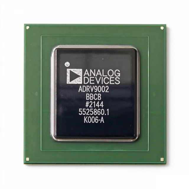
ADRV9002BBCZ-REEL - Dual RF Transceiver 30MHz-6GHz | Analog Devices
The ADRV9002BBCZ-REEL is a highly integrated, dual-channel RF transceiver from Analog Devices, designed for both narrow-band and wideband applications. It operates over a frequency range of 30 MHz to 6 GHz, making it suitable for a wide variety of wireless communication systems. The device integrates dual-channel transmitters, dual-channel receivers, synthesizers, and digital signal processing functions in a compact 196-ball TFBGA/CSPBGA package. This tape-and-reel variant is optimized for high-volume production. An RF transceiver is a device that combines both a transmitter and a receiver in a single package, sharing common circuitry. The ADRV9002 is a system-on-chip (SoC) that integrates the RF front-end, analog-to-digital converters (ADCs), digital-to-analog converters (DACs), and digital signal processing (DSP) blocks. This level of integration reduces component count, board space, and design complexity, making it ideal for software-defined radios (SDR) and other advanced wireless systems. Key features of the ADRV9002 include dual-channel operation, a wide frequency range of 30 MHz to 6 GHz, and support for both narrow-band and wideband signals. The device offers high linearity and dynamic range, ensuring reliable performance in demanding environments. It also includes integrated synthesizers, reducing the need for external PLLs and VCOs. The power output is 7.8 dBm, and the device operates from a single 3.3V supply. The ADRV9002 uses advanced CMOS technology to achieve high performance with low power consumption. The digital signal processing functions include filtering, gain control, and calibration, which are configurable via a serial peripheral interface (SPI). The device supports multiple operating modes, including TDD and FDD, and can be programmed for various bandwidths and sample rates. The integrated synthesizers provide low phase noise, essential for high-quality signal transmission and reception. Typical applications for the ADRV9002 include 5G NR base stations, small cells, macro cells, and other wireless infrastructure. It is also used in military and aerospace communications, radar systems, and test and measurement equipment. The wide frequency range and dual-channel capability make it a versatile choice for many RF designs. When designing with the ADRV9002, careful attention must be paid to power supply decoupling and thermal management. The device requires a clean 3.3V supply and adequate grounding to achieve optimal performance. The exposed pad on the package should be soldered to a thermal via array to dissipate heat effectively.
ADRV9003BBCZ - 1x1 RF Transceiver 30MHz-6GHz | Analog Devices
The ADRV9003BBCZ is a highly integrated, single-channel RF transceiver from Analog Devices, designed for a wide range of wireless applications. It operates from 30 MHz to 6 GHz, covering HF, VHF, UHF, and microwave bands, and features a single-channel transmitter, dual-channel receivers, integrated synthesizers, and extensive digital signal processing functions. The device is housed in a 196-pin CSP-BGA package, making it suitable for compact, high-performance designs. An RF transceiver is a device that combines a transmitter and a receiver in a single package, sharing common circuitry. It is a fundamental building block in wireless communication systems, enabling bidirectional data transfer over radio frequencies. The ADRV9003 integrates the RF front-end, analog-to-digital converters (ADCs), digital-to-analog converters (DACs), and digital signal processing, reducing the need for external components and simplifying system design. Key features of the ADRV9003 include a wide frequency range of 30 MHz to 6 GHz, a maximum sample rate of 61.44 MSPS, and high linearity and dynamic range. The device supports both FDD and TDD operation, making it versatile for various communication standards. It also includes integrated synthesizers and a digital interface, allowing for flexible configuration and control. The ADRV9003 utilizes advanced mixed-signal technology, integrating multiple functions that traditionally required separate components. Its architecture enables high performance while minimizing power consumption and board space. The device is designed for applications such as 5G base stations, software-defined radios, and test and measurement equipment, where high performance and flexibility are critical. Typical applications include 5G wireless infrastructure, point-to-point microwave links, and military communications. The wide frequency range and high dynamic range make it suitable for demanding environments. The device's integrated DSP functions allow for real-time signal processing, reducing the load on external processors. When designing with the ADRV9003, careful attention must be paid to power supply decoupling and thermal management. The device requires multiple supply rails, and proper filtering is essential to achieve optimal performance. The CSP-BGA package requires a well-designed PCB layout with adequate thermal vias to dissipate heat effectively.
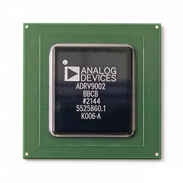
ADRV9003BBCZ-REEL - 30MHz-6GHz RF Transceiver | ADI
Analog Devices ADRV9003BBCZ-REEL is a highly integrated RF transceiver covering 30 MHz to 6 GHz, with a single-channel transmitter, dual-channel receivers, integrated synthesizers, and extensive digital signal processing functions. The device is supplied on tape and reel for high-volume surface-mount assembly and is part of the ADRV900x family used in wireless infrastructure and defense radio systems. The antenna is not included, so external antenna circuitry is required. An RF transceiver is a combined transmitter and receiver used in radio systems to convert between baseband digital data and modulated RF signals. In an ADRV9003-class transceiver, integrated synthesizers generate local-oscillator signals, while on-chip DSP performs filtering, gain control, calibration, and data formatting before handoff to an FPGA or SoC. This integration replaces multiple discrete IF/RF components and shortens radio design cycles. Key features of the ADRV9003BBCZ-REEL include the 30 MHz to 6 GHz operational range, 1T2R channel architecture, high linearity, high dynamic range, integrated synthesizers, and digital signal processing capabilities. According to the ADI product page, the device is optimized for high performance in demanding communications links. From an architecture perspective, the 1T2R configuration suits TDD systems that need one transmit path and two receive paths, such as base stations with receive diversity or dual-direction monitoring. The integrated DSP offloads many radio functions from the baseband processor, reducing host FPGA resource usage and supporting multiband software-defined radios. Typical applications include 5G/4G small cells, software-defined radios, phased-array radar feeds, industrial IoT gateways, satellite communications, and test-and-measurement instruments. In these systems, the device's bandwidth and linearity reduce error vector magnitude (EVM) and improve sensitivity. When designing with the ADRV9003BBCZ-REEL, pay attention to board-level thermal management for the BGA package and clean supply filtering near the RF pins. A well-controlled RF layout with proper impedance matching and grounding is essential to achieve the high dynamic range promised by the datasheet.
ADRV9004BBCZ - Dual RF Transceiver 30MHz-6GHz | Analog Devices
The ADRV9004BBCZ is a highly integrated, dual-channel RF transceiver from Analog Devices, designed for narrow-band and wideband applications. It operates over a frequency range of 30 MHz to 6 GHz, covering HF, VHF, UHF, and microwave bands. The device integrates dual-channel transmitters, dual-channel receivers, integrated synthesizers, and digital signal processing functions into a single 196-ball CSP_BGA package (12 mm × 12 mm). It supports configurable CMOS or LVDS serial synchronous interfaces (SSI) for high and low data rate communication. An RF transceiver is a device that combines a transmitter and receiver, sharing common circuitry or a single housing. In the hierarchy of wireless communication systems, an RF transceiver is a key component within the radio frequency front-end, which connects the antenna to the baseband processor. The ADRV9004BBCZ is a software-defined radio (SDR) solution, enabling flexible modulation schemes and frequency agility through digital control. Key features include dual-channel operation, wide frequency coverage, high linearity, and high dynamic range. The device supports both narrow-band and wideband signal processing, making it suitable for a variety of communication standards. It operates with 1.3V and 1.8V power supplies, and is available in a tray packaging. The ADRV9004BBCZ is RoHS compliant and is an active product in Analog Devices' portfolio. Technically, the ADRV9004BBCZ integrates multiple synthesizers, mixers, filters, and ADCs/DACs, providing a complete RF front-end solution. Its digital signal processing capabilities include filtering, gain control, and calibration algorithms, reducing the need for external components. The device is designed for high performance, with excellent noise figure and linearity, ensuring reliable communication in demanding environments. Typical applications include cellular base stations, point-to-point microwave links, satellite communications, and defense systems. Its wide frequency range and dual-channel capability make it ideal for MIMO and diversity schemes. The compact package and integrated functionality reduce board space and design complexity. When designing with the ADRV9004BBCZ, careful attention must be paid to power supply decoupling and thermal management. The device's thermal resistance values are specified per JEDEC standards (JESD51-12), and proper PCB layout with adequate ground planes is essential for optimal RF performance.

ADRV9004BBCZ-REEL - Dual RF Transceiver 30MHz-6GHz | Analog Devices
The ADRV9004BBCZ-REEL is a highly integrated, dual-channel RF transceiver from Analog Devices, designed for a wide range of wireless applications. It operates over a frequency range of 30 MHz to 6 GHz, making it suitable for both narrow-band and wideband communication systems. The device integrates dual-channel transmitters, dual-channel receivers, integrated synthesizers, and digital signal processing functions into a single 196-ball CSP_BGA package, offering a compact solution for space-constrained designs. An RF transceiver is a device that combines both transmit and receive functions in a single module, enabling bidirectional communication over radio frequencies. In the hierarchy of wireless communication, an RF transceiver sits between the baseband processor and the antenna, handling the conversion of digital data to RF signals for transmission and RF signals to digital data for reception. The ADRV9004 belongs to the family of software-defined radio (SDR) transceivers, which allow flexible configuration of frequency, bandwidth, and modulation schemes via software, making them ideal for multi-standard and multi-band systems. Key features of the ADRV9004BBCZ-REEL include dual-channel operation, a wide frequency range from 30 MHz to 6 GHz, and a maximum output power of 7.8 dBm. The device supports both CMOS and LVDS serial synchronous interfaces (SSI) for high data rate and low data rate communication with baseband processors. Its high linearity and dynamic range ensure reliable performance in demanding environments, while the integrated synthesizers reduce external component count and simplify design. Technically, the ADRV9004 employs advanced mixed-signal processing, including digital filtering and calibration algorithms, to optimize performance across its operating range. The device is packaged in a 12 mm × 12 mm, 196-ball chip scale package ball grid array (CSP_BGA), which provides excellent thermal and electrical performance. The REEL suffix indicates tape-and-reel packaging, suitable for automated assembly in high-volume production. Typical applications include 5G NR small cells, point-to-point microwave links, satellite communications, and test and measurement equipment. The wide frequency range and dual-channel capability make it a versatile choice for both commercial and industrial wireless systems. When designing with the ADRV9004, careful attention must be paid to power supply decoupling and PCB layout to maintain signal integrity and minimize noise. The device requires multiple supply rails, and proper filtering is essential to achieve the specified performance.
ADRV9009BBCZ - Dual RF Transceiver 75MHz-6GHz | Analog Devices
The ADRV9009BBCZ is a highly integrated, radio frequency (RF), agile transceiver from Analog Devices, offering dual transmitters and receivers, integrated synthesizers, and digital signal processing functions. It operates over a frequency range of 75 MHz to 6 GHz, making it suitable for a wide variety of wireless applications. The device is housed in a 196-pin CSP-BGA package and is designed for surface mount assembly. An RF transceiver is a device that combines both a transmitter and a receiver in a single package, enabling bidirectional communication over radio frequencies. The ADRV9009 is a key component in modern wireless systems, providing the analog and digital signal processing needed to convert between baseband data and RF signals. It integrates multiple functions such as filtering, amplification, and frequency synthesis, reducing the need for external components and simplifying system design. Key features of the ADRV9009BBCZ include support for 3G, 4G, and 5G macro cell time division duplex (TDD) base station applications, dual transmitters and receivers, and an observation receiver for transmit monitoring. The device also includes integrated synthesizers and digital signal processing, enabling high performance with low power consumption. The operating temperature range is -40°C to +85°C, and the device is RoHS compliant. The ADRV9009 utilizes advanced mixed-signal processing to achieve high dynamic range and low noise, essential for demanding cellular infrastructure applications. Its agile frequency synthesis allows rapid hopping across the 75 MHz to 6 GHz band, supporting multi-band and multi-standard radios. The integrated digital signal processing offloads the baseband processor, reducing system complexity and power consumption. Typical applications include 3G/4G/5G macro cell base stations, small cells, and other wireless infrastructure. The device is also used in phased array radar, satellite communications, and test and measurement equipment. Its wide frequency range and high integration make it a versatile choice for many RF systems. When designing with the ADRV9009, careful attention must be paid to power supply decoupling and thermal management. The device requires multiple supply rails (1.3V, 1.8V, 1.89V) and a well-designed PCB layout to achieve optimal performance. Reference designs and evaluation boards are available from Analog Devices to accelerate development.
ADRV9009BBCZ-REEL - Dual RF Transceiver 75MHz-6GHz | Analog Devices
The ADRV9009BBCZ-REEL is a highly integrated, radio frequency (RF), agile transceiver from Analog Devices, offering dual transmitters and receivers, integrated synthesizers, and digital signal processing functions. It operates over a frequency range of 75 MHz to 6 GHz, making it suitable for a wide variety of wireless applications. The device is packaged in a 196-pin CSP-BGA and is provided in tape and reel packaging for automated assembly. An RF transceiver is a device that combines both a transmitter and a receiver in a single package, sharing common circuitry. The ADRV9009 is a system-on-chip (SoC) that integrates the RF front-end, mixed-signal converters, and digital signal processing, reducing the need for external components. It is part of the broader category of radio frequency integrated circuits (RFICs), which are essential for modern wireless communication systems. Key features of the ADRV9009 include dual-channel operation, support for frequency division duplexing (FDD) and time division duplexing (TDD), and a JESD204B interface for high-speed data transfer to FPGAs or processors. The device also includes observation receivers (ORx) for digital predistortion and monitoring, and it supports a wide bandwidth of up to 200 MHz per channel. The integrated synthesizers and clock management simplify system design. Technically, the ADRV9009 employs advanced mixed-signal processing, including high-speed ADCs and DACs, and digital filters. It operates from multiple supply rails (1.3V, 1.8V, 1.89V) and includes power management features. The device is designed for high linearity and low noise, ensuring excellent signal quality. Its flexible architecture allows configuration for various standards, including 2G/3G/4G/5G cellular, and it is also used in military and aerospace applications. Typical applications include cellular base stations, small cells, phased array radar, and software-defined radio (SDR) systems. The ADRV9009's wide frequency range and dual-channel capability make it ideal for MIMO and diversity schemes. It is also used in test and measurement equipment and satellite communications. When designing with the ADRV9009, careful attention must be paid to power supply decoupling and thermal management. The device's high integration requires a well-designed PCB layout to minimize noise and ensure stable operation. The JESD204B interface simplifies data transfer but requires proper clocking and synchronization.