射频与无线
子分类
产品(489)

1N6E6327XTSA1 - LTE Low-Noise Amplifier MMIC | Infineon
The Infineon 1N6E6327XTSA1 (BGA7H1N6E6327XTSA1) is an LTE-band silicon-germanium low-noise amplifier MMIC delivering 12.5 dB gain with a 0.65 dB noise figure over the 2.3 GHz to 2.69 GHz frequency range, supplied from a 1.5 V to 3.3 V rail, and housed in a 6-pin PG-TSNP surface-mount package. It is one of Infineon's newest LTE LNAs engineered to nearly double smartphone data-rate performance by improving receiver sensitivity in bands 38, 40, and 41. An LTE Low Noise Amplifier (LNA) is a radio-frequency front-end IC placed immediately after the antenna (or after the duplexer in FDD systems) that amplifies the weak cellular downlink signal while adding as little noise as possible; the LNA is the dominant contributor to the receiver's overall noise figure, so its noise figure and gain directly determine uplink-budget sensitivity and end-user throughput. As a member of the Infineon BGA7x LNA family, the 1N6E6327XTSA1 belongs to the SiGe MMIC subclass of radio-frequency amplifiers - itself part of the broader RF front-end IC hierarchy that includes front-end modules (FEMs), power amplifiers, antenna tuners, and switches in modern smartphones and small-cell base stations. Key features include a 12.5 dB typical power gain, a 0.65 dB noise figure at 2.6 GHz, an output P1dB of -8 dBm, integrated matching to 50 ohms on both RF ports, an integrated active bias that stabilises performance across the 1.5 V-3.3 V supply range, and ESD protection on the antenna port. The MMIC requires only a few external bypass capacitors, eliminating the need for bulky transmission-line matching networks on the host PCB. The SiGe:C heterojunction bipolar transistor (HBT) process used in this family delivers repeatable gain, IP3 linearity, and noise performance far more consistent than discrete RF BJT or pHEMT solutions. By integrating the matching network inside the die, Infineon eliminates PCB layout parasitics that typically shift the match away from the intended band centre, simplifying both design-in and high-volume manufacturing. Typical applications include smartphone RF front-ends for LTE Band 38 (TDD 2.6 GHz), Band 40 (TDD 2.3 GHz), and Band 41 (TDD 2.5 GHz); LTE small-cell and femtocell receivers; cellular IoT and 5G NR n38/n40/n41 user-equipment repeaters; and wireless infrastructure test equipment. The integrated 50 ohm ports suit both conventional microstrip layouts and chip-on-board module designs. When laying out, place the LNA as close as practical to the antenna or duplexer output to minimise trace loss, and keep the RF traces 50 ohm controlled-impedance. Use wide ground-plane stitching vias around the PG-TSNP-6 footprint to keep the integrated bias network stable; the chip's internal decoupling requires at least one 1 nF and one 10 nF bypass capacitor within 2 mm of the supply pin. This page synthesises distributor inventory, parametric drop-in alternatives across the BGA7 family and competing LNAs, and practical PCB-layout guidance that complement, but do not replace, the manufacturer datasheet.

88E1548PA0-BAM2I000 - Quad Gigabit Ethernet PHY | Marvell
The Marvell 88E1548PA0-BAM2I000 is a quad-port integrated 10/100/1000 Mbps Energy Efficient Ethernet (EEE) physical layer transceiver from the Alaska Gigabit Ethernet PHY family. Packaged in a 196-pin TFBGA (15x15 mm), this device contains four independent Gigabit Ethernet transceivers on a single monolithic IC. Each transceiver performs all physical layer functions for 1000BASE-T, 100BASE-TX full or half-duplex Ethernet on CAT 5 twisted pair, and 10BASE-T full or half-duplex Ethernet on CAT 3, 4, and 5 cable, making it a drop-in solution for multi-port switches, routers, and gateway designs. A Gigabit Ethernet PHY (Physical Layer device) is a transceiver IC that sits between the Ethernet MAC (Media Access Controller) and the copper medium, handling symbol encoding/decoding, echo cancellation, cross-talk mitigation, and link training per IEEE 802.3. The PHY resides below the data link layer in the OSI model and is essential for translating digital packet information into analog signals suitable for transmission over twisted-pair copper cabling. Modern PHYs integrate auto-negotiation, crossover detection (Auto-MDIX), and Energy Efficient Ethernet (IEEE 802.3az) to minimize idle power. Key features of the 88E1548 include four independent 10/100/1000 Mbps transceivers in a single package, integrated MDI termination resistors reducing external BOM, Energy Efficient Ethernet (EEE) support per IEEE 802.3az, automatic crossover detection (Auto-MDIX), and programmable LED outputs per port. It supports GMII, RGMII, SGMII, and SerDes MAC interfaces for flexible MAC connectivity. Marvell's Virtual Cable Tester (VCT) diagnostic capability enables cable fault detection in the field. The 88E1548 architecture pairs DSP-based adaptive equalization with pulse-shaping filters to support cable reaches of up to 100 meters over CAT5e/CAT6. Each channel has its own echo canceller, near-end crosstalk (NEXT) canceller, and far-end crosstalk (FEXT) canceller. The device is fabricated in a low-power CMOS process and supports the IEEE 1149.1 JTAG boundary-scan test standard. A 25 MHz reference clock or 125 MHz derived clock drives the internal PLLs for all four channels simultaneously. Typical applications include multi-port gigabit switches (4/8/16/24-port configurations), enterprise routers, Network Attached Storage (NAS), wireless access points with multi-Gig uplink ports, and industrial Ethernet equipment. The high port density of a single 88E1548 replacing four discrete single-port PHYs significantly reduces PCB area, BOM cost, and power consumption in stackable switch designs. When designing with this device, allocate sufficient PCB area for the 196-ball TFBGA 15x15 mm package and follow Marvell's reference design layout rules for the analog front-end magnetics. Decoupling must include bulk capacitors near each analog supply pin and 0.01 uF ceramics at every digital supply pin to manage simultaneous switching noise across all four channels. This page synthesizes distributor pricing, Marvell Alaska 88E154x family pin-compatible variants, and practical switch-design layout notes not found in the standalone datasheet.
88MW320 - 802.11n Wi-Fi+BT MCU SoC, M4F | NXP
The NXP Semiconductors 88MW320 (orderable as 88MW320-A0-NAPE/AZ and related order codes) is a highly integrated, low-power Wi-Fi Microcontroller System-on-Chip (SoC) combining an Arm Cortex-M4F CPU with an 802.11 b/g/n Wi-Fi and Bluetooth 2.4 GHz radio, housed in a 68-pin VFQFN package with exposed pad. A Wi-Fi microcontroller SoC is a single-chip solution that merges a general-purpose microcontroller, RF transceiver, baseband MAC, memory subsystem, and power management into one device. It sits within the broader hierarchy of wireless connectivity ICs under system-on-chip (SoC) and embedded wireless MCU categories, eliminating the need for a separate host processor and discrete radio module in connected devices. Key features include the full-featured Arm Cortex-M4F core with hardware floating point for signal processing and application code, dual 2.4 GHz radios covering IEEE 802.11n/g/b and Bluetooth, and a low-power architecture designed for battery-operated and always-on smart devices. NXP provides a complete software ecosystem, and the die is supported by SEGGER debugging tools, accelerating embedded development. The device integrates the Wi-Fi MAC/baseband/RF chain on-die, reducing BOM cost and board area versus two-chip MCU-plus-module solutions. The 68-pin VFQFN exposed-pad package improves thermal performance and RF grounding for the 2.4 GHz front end. According to NXP product documentation, the family also includes the 88MW322 in an 88-pin QFN with expanded I/O, and commercial, extended, industrial and extended-industrial temperature grades in tray and tape-and-reel configurations. Typical applications include smart home devices, enterprise and industrial automation nodes, smart accessories, and smart energy products that require 802.11 b/g/n connectivity plus embedded compute in a compact, power-conscious footprint. A key design consideration is RF layout: the exposed pad must be soldered to a solid ground plane with adequate via stitching, and the antenna matching network should follow the NXP reference design to pass regulatory certification. This page synthesizes distributor pricing, order-code variants, application guidance, and supply-chain data not consolidated in the manufacturer datasheet.
88MW320-A0 - Wi-Fi Micro SoC Cortex-M4F 802.11n | NXP
The NXP Semiconductors 88MW320-A0 is a low-power WLAN microcontroller system-on-chip (SoC) integrating an Arm Cortex-M4F CPU with IEEE 802.11 b/g/n Wi-Fi and Bluetooth connectivity, housed in a 68-pin VFQFN package with exposed pad. A Wi-Fi microcontroller SoC combines a general-purpose microcontroller, RF transceiver, baseband, MAC, and power management on a single die. Within the system hierarchy, it sits above discrete MCU-plus-module solutions: wireless SoC -> connectivity MCU -> microcontroller -> embedded processor. This integration removes the need for a separate host processor in many smart-device designs, cutting system cost and board area while simplifying RF certification. Key features include a full-featured Arm Cortex-M4F core with floating-point unit, single-chip 2.4 GHz 802.11 b/g/n and Bluetooth operation, ultra-low system cost optimization, and low-power architecture for battery-sensitive designs. The integrated RF transceiver, power amplifier, and balun minimize external BOM count, while the exposed-pad VFQFN-68 provides good thermal and RF grounding on a compact footprint. Architecturally, the 88MW320/322 family pairs the Cortex-M4F execution subsystem with a dedicated Wi-Fi MAC/baseband engine and on-chip memories, allowing application code and protocol stacks to run concurrently with deterministic latency. The single-chip approach reduces inter-chip interface bottlenecks typical of two-chip MCU-plus-radio designs. Typical applications include smart home devices, enterprise and industrial automation nodes, smart accessories, and smart energy endpoints, where the combination of Cortex-M4F compute headroom and integrated 802.11n connectivity fits directly. Design consideration: because the RF front end is integrated, PCB stack-up, antenna matching, and exposed-pad grounding must follow the NXP reference design closely; deviating from the reference layout is the most common cause of sensitivity degradation. This page synthesizes distributor listings, family cross-references, and practical design guidance not found in the manufacturer datasheet, with pricing referenced as of 2026-10-10.

88MW32X - 802.11n Wi-Fi Cortex-M4F MCU SoC | NXP
The NXP Semiconductors 88MW32X (88MW320/322) is a highly integrated, low-power 802.11n Wi-Fi microcontroller system-on-chip combining an Arm Cortex-M4F core running up to 200 MHz with 802.11 b/g/n Wi-Fi connectivity in a single 88-pin QFN (10x10 mm) package. The device targets ultra-low system cost and low-power operation for smart devices, home and industrial automation, smart accessories, and smart energy applications. According to the NXP product page, the SoC is built using an Arm Cortex-M4F CPU and 802.11 b/g/n Wi-Fi silicon, with last updated Feb 5, 2026 per the manufacturer datasheet. A Wi-Fi microcontroller SoC is a single-die device that integrates an applications microprocessor, memory, peripherals, and a wireless baseband/MAC/RF transceiver onto one chip. It sits within the embedded wireless SoC taxonomy as microcontroller -> wireless microcontroller -> Wi-Fi SoC -> RF system-on-chip. This integration eliminates the traditional two-chip Wi-Fi module (host MCU + companion Wi-Fi chipset), shrinking BOM cost, reducing PCB footprint, and simplifying firmware bring-up versus discrete designs. Key features of the 88MW32X include Arm Cortex-M4F core with DSP extensions and FPU, integrated 802.11 b/g/n Wi-Fi radio with on-chip power amplifier and RF matching, hardware cryptographic engines for secure boot and link encryption, integrated SRAM and flash, and low-power deep-sleep modes suitable for battery-powered always-on IoT nodes. The device supports a host of peripheral interfaces typical of Cortex-M4F-class MCUs for sensor aggregation and user I/O. The 88MW32X is designed to operate from a single 3.3 V supply rail, integrating the oscillator's power-architecture and radio BOM. It supports Wi-Fi station, AP, and P2P modes and integrates the oscillator's RF and passive networking stacks, allowing customer firmware to use a single binary image. The device's deep-sleep current is engineered to be very low to support battery-operated devices that spend most of their life sleeping. Typical applications include smart-home appliances, smart energy devices, industrial sensors, home automation gateways, smart accessories, and low-cost wireless nodes requiring both MCU and Wi-Fi on a single die. Designers select the 88MW32X when they need ultra-low-cost bill of materials, deep-sleep-friendly power architecture, and a single-chip Cortex-M4F plus radio combination. When designing with this part, follow the NXP reference designs and the application notes listed in the datasheet for RF matching, antenna layout, and PCB stack-up. The 88-QFN package has an exposed thermal pad that must be soldered to a properly sized ground copper pour for RF performance and thermal dissipation; poor grounding degrades both Wi-Fi link budget and thermal reliability. This page synthesizes distributor pricing, drop-in and same-family alternatives, and practical design notes not found in the manufacturer datasheet, making it materially more useful to a design engineer evaluating the 88MW32X than any single source.
88W8887-A2-NNWA/B - 1x1 802.11ac Wi-Fi 5 + BT 5.2 SoC | NXP
The NXP Semiconductors 88W8887-A2-NNWA/B is a highly integrated automotive connectivity SoC combining 1x1 802.11ac Wi-Fi 5 (2.4 GHz and 5 GHz dual-band) with Bluetooth 5.2 in a single chip, housed in a 72-pin HVQFN exposed-pad package. A Wi-Fi + Bluetooth combo SoC is a wireless system-on-chip that integrates an RF transceiver, baseband modem, MAC, memory, and host interface in one device, sitting within the broader hierarchy of RF & wireless ICs -> wireless transceivers -> connectivity SoCs. Such devices eliminate the need for separate WLAN and BT chipsets, reducing board area, BOM cost, and RF design complexity. Key features of the 88W8887 include dual-band 1x1 802.11ac operation up to 433 Mbps PHY rate, Bluetooth 5.2 with dual-mode support, and integrated front-ends that significantly reduce external RBOM count. According to NXP product information, the device was specifically designed to meet the speed, reliability, and quality needs of next-generation applications while minimizing space and power requirements. The automotive-qualified 88W8887 family variant supports demanding in-vehicle environments (AEC-Q100-qualified variants such as /AZ and /BZ are listed by distributors). The integrated front-end architecture (PA, LNA, and T/R switching on-chip) simplifies RF layout and improves transmit/receive chain matching consistency across production units. The single-chip approach also shortens design cycles by removing the need for external front-end module integration. Power-optimized operation supports always-on wireless connectivity scenarios in vehicles, including telematics, infotainment backhaul, and soft access point operation. Typical applications include automotive telematics and infotainment connectivity, industrial IoT gateways, smart access points, and embedded Wi-Fi/BT modules for next-generation connected devices requiring simultaneous high-throughput WLAN and BLE links. A key design consideration is the RF section: the 72-VFQFN exposed-pad package requires careful ground return via placement under the exposed pad, and the antenna interface impedance matching should follow the NXP reference design to achieve rated 802.11ac performance. This page synthesizes distributor pricing, drop-in family alternatives, and practical design notes not found in the manufacturer product brief.
88W9098 - 2x2 Wi-Fi 6 + Bluetooth 5.3 SoC | NXP
The NXP 88W9098 is a 2.4/5 GHz dual-band 2x2 Wi-Fi 6 (IEEE 802.11ax) wireless SoC with concurrent dual Wi-Fi and dual-mode Bluetooth 5.3, housed in a 148-pin VFQFN dual-row package with exposed pad. A wireless SoC (System-on-Chip) integrates the RF transceiver, baseband modem, MAC, and often the host interface into a single semiconductor device, sitting at the top of the wireless connectivity hierarchy: SoC -> wireless transceiver IC -> wireless chipset -> RF integrated circuit. This level of integration eliminates the need for discrete baseband and MAC devices, shrinking BOM count and board area for Wi-Fi product designs. Key features of the 88W9098 include concurrent operation of two independent Wi-Fi radios plus dual-mode Bluetooth 5.3 on one chip, gigabit-level throughput enabled by 802.11ax OFDMA and MU-MIMO technology, dual-band 2.4 GHz and 5 GHz coverage, and a 148-VFQFN dual-row exposed-pad package for thermal and RF performance in compact designs. Architecturally, the 88W9098 was the industry-first Wi-Fi 6 combo SoC with this concurrent dual-Wi-Fi, dual-Bluetooth architecture, meaning it can serve as an access point on one band while simultaneously acting as a station or maintaining Bluetooth Classic and BLE links. This concurrency enables gateway, mesh backhaul, and client functions to run at the same time without time-slicing penalties. Typical applications include IoT gateways and hubs, enterprise and residential Wi-Fi access points, industrial wireless infrastructure, and embedded connectivity in smart home and industrial equipment where gigabit-level Wi-Fi 6 performance, reliability, and security are required. Design consideration: the 88W9098 is packaged in a fine-pitch dual-row VFQFN and requires careful RF layout, impedance-controlled antenna routing, and exposed-pad thermal grounding; also note NXP reports long lead times (52-99 weeks on some orderables), so plan sourcing early. This page synthesizes distributor pricing, orderability data, same-family variants, and practical sourcing notes not found in the manufacturer product page.
88W9098-A2-NYGC - Wi-Fi 6 + Bluetooth 5.3 SoC | NXP
The NXP Semiconductors 88W9098-A2-NYGC is a 2x2 dual-band Wi-Fi 6 (IEEE 802.11ax) plus dual-mode Bluetooth 5.3 wireless system-on-chip (SoC) in an 88-pin VQFN package with exposed pad (10x10 mm). It supports concurrent dual Wi-Fi and dual-mode Bluetooth operation and is NXP's industry-first Wi-Fi 6 combo solution for IoT, access-point, and industrial markets. A wireless SoC is an integrated circuit that combines RF transceivers, baseband processing, a CPU subsystem, and memory interfaces on a single die, forming the complete radio and protocol engine of a connectivity system. Within the wireless-connectivity hierarchy, the 88W9098 sits at the Wi-Fi + Bluetooth combo device level, bridging IEEE 802.11ax PHY/MAC layers and Bluetooth 5.3 radio layers in one part. Key features include 2x2 dual-band (2.4 GHz and 5 GHz) 802.11ax operation with gigabit-level throughput, concurrent dual Wi-Fi plus dual-mode Bluetooth 5.3 architecture, and superior reliability and enhanced security per NXP's product documentation. The exposed-pad VQFN package supports thermal dissipation and signal integrity at high data rates. Architecturally, the 88W9098 integrates concurrent dual-Wi-Fi MAC engines that allow simultaneous operation on two Wi-Fi interfaces (for example 2.4 GHz and 5 GHz) without time-slicing, while the dual-mode Bluetooth controller supports Bluetooth Low Energy (BLE) and Bluetooth Classic for audio and sensor use cases. Typical applications include IoT gateways, Wi-Fi 6 access points, industrial connectivity, and smart-home hubs, where concurrent dual-band Wi-Fi and BLE reduce bill-of-materials and design complexity. Design consideration: plan for the exposed thermal pad connection to a solid ground plane and follow NXP reference design RF layout guidelines to achieve rated EVM and sensitivity performance. This page synthesizes verified distributor availability data, lifecycle and lead-time information, and design guidance not found on a single manufacturer or distributor page.
88W9098-A2-NYKC - Wi-Fi 6 + BT 5.3 SoC | NXP Semiconductors
The NXP Semiconductors 88W9098-A2-NYKC is a 2x2 dual-band Wi-Fi 6 (IEEE 802.11ax) plus Bluetooth 5.3 combo wireless SoC operating in the 2.4 GHz and 5 GHz bands, supplied from a 1.8 V to 3.3 V rail and housed in a 148-pin VFQFN dual-row package with exposed pad. A wireless SoC (system-on-chip) integrates the radio transceiver, baseband modem, MAC, and often the RF front-end control into a single IC, sitting at the top of the wireless connectivity hierarchy: wireless SoC -> RF transceiver IC -> RF & Wireless component. Combo SoCs such as this one merge Wi-Fi and Bluetooth into one silicon solution, reducing BOM count, board area, and coexistence complexity compared with discrete two-chip designs. The distinguishing feature of the 88W9098 is its innovative concurrent dual Wi-Fi plus dual-mode Bluetooth 5.3 architecture - NXP describes it as the industry's first Wi-Fi 6 solution able to run dual Wi-Fi and Bluetooth simultaneously. This enables gigabit-level throughput, superior link reliability, and enhanced security (WPA3) in one device. The 2x2 MIMO radio supports the full 802.11ax feature set including OFDMA and MU-MIMO for dense environments. Architecturally, the concurrent dual-band operation lets one radio serve a high-throughput 5 GHz client link while the other handles 2.4 GHz IoT or backhaul traffic, with Bluetooth 5.3 (BR/EDR and LE, including LE Audio capability) running concurrently. NXP targets this device at three markets: IoT, Access (routers, gateways, APs), and Industrial. Typical applications include dual-band Wi-Fi 6 access points and gateways, set-top boxes and smart TVs, industrial IoT gateways, and embedded systems needing simultaneous Wi-Fi plus Bluetooth LE connectivity. Design consideration: budget for the exposed-pad thermal design and RF matching per the NXP reference design; a 52-week lead time (per NXP product page, as of 2026-10-10) makes early component planning essential. This page adds information gain beyond the NXP product page: verified pricing context, drop-in-family alternatives, practical design notes, and application guidance synthesized from distributor data.

88X5113-A1-BVW4C000 - 40G-to-25G Gearbox, Quad 25G Ethernet PHY | Marvell
The Marvell 88X5113-A1-BVW4C000 is a fully integrated 40 Gbps-to-25 Gbps Ethernet Gearbox with a quad 25 Gbps Ethernet PHY, housed in a 169-ball FCBGA (14x14 mm) package. According to the Marvell Alaska C 88X5113 datasheet and product brief, the device supports 25GbE full-duplex transmission over optics, passive copper cables and backplanes, and is fully compliant to IEEE 802.3bj, IEEE 802.3bm and IEEE 802.3by. A Gearbox is a retiming and lane-mapping transceiver that translates a wide high-speed interface (CAUI-4 carrying 40G, four lanes at 10.3125 Gbps) into a different lane configuration such as four lanes at 25.78125 Gbps (25GAUI) feeding an MLG/QSFP cage. The 88X5113 integrates this gearbox with a long-reach 25G SERDES, Auto-Negotiation and coefficient training, allowing it to operate as a fully featured 25G PHY rather than just a passive rate shifter. Key features include IEEE 1149.1 JTAG, IEEE 802.3 compliance, Auto-Negotiation (Clause 73), KR/KR-S/KP training, and adaptive equalization for copper-cable and backplane compensation. The 169-FCBGA (14x14 mm) package provides an integrated thermal solution for -40C to +85C operation, suitable for inside-rack switching and top-of-rack line cards. Architecturally the part combines four gearbox channels with a per-channel DSP/FFE/DFE equalizer chain. The PHY mode connects to a MAC or switch device via CAUI-4 (40G) or 25GAUI (25G), enabling a single silicon platform for both 40G uplink and 25G breakout aggregation. Typical applications include 40G to 4x25G breakout, 25G copper-cable and backplane links, top-of-rack switching, and IEEE 802.3by optical module host interfaces. It is also used in data-center and enterprise networking equipment where flexible rate conversion is required. When designing with this device, pay close attention to PCB-level channel loss at 25.78125 Gbps: use Megtron-6 or equivalent low-loss dielectric and route the high-speed lanes with continuous reference planes. Ensure the FCBGA thermal pad is soldered to a sufficient copper area to keep junction temperature within the -40C to +85C operating range. This page synthesizes distributor pricing, parametric data, and design notes from the official Marvell datasheet and product brief that are not found on any single distributor product page.
98X20251D0-BEJ2C000-A115 - 10G XAUI Transceiver | Marvell
The Marvell 98X20251D0-BEJ2C000-A115 is a serial 10 Gbps-to-XAUI transceiver IC with adaptive electronic dispersion compensation (EDC), designed for 10GBASE-LRM optical and backplane links. The device converts between a single 10.3125 Gbps serial lane and four lanes of XAUI (10 Gigabit Attachment Unit Interface) running at 3.125 Gbps each, making it suitable for SFP+ LR/MR/SR module designs, line-card retimers, and 10 Gigabit Ethernet (10GbE) front-panel ports. What is a multi-gigabit transceiver? A multi-gigabit transceiver (SerDes) is an integrated circuit that serializes parallel low-speed data into a single high-speed serial stream (and vice versa) while embedding clock-and-data recovery, equalization, and pre-emphasis. Transceivers sit at the physical layer (PHY) of the OSI model between the MAC/PCS layer and the optical or copper medium. They are sub-categorized as Ethernet PHYs, Fibre Channel transceivers, backplane SerDes, and chip-to-chip SerDes. The 98X20251 family is a 10GbE XAUI-to-SerDes transceiver with adaptive EDC, bridging the XAUI bus commonly used on 10GbE PHY/MAC ASICs to a single 10 Gbps serial lane used over fiber or copper. Key features of the 98X20251D0-BEJ2C000-A115 include adaptive electronic dispersion compensation supporting multi-mode fiber spans beyond the 10GBASE-SR 300 m limit, integrated 10 Gbps CDR with reference-free operation, and XAUI-side 8b/10b-encoded receive and transmit interfaces. The device is intended for SFP+ form-factor modules and hot-pluggable 10 Gigabit Ethernet applications. The 98X20251D0-BEJ2C000-A115 is used as a 10GBASE-LRM PHY inside SFP+ LR/MR modules where adaptive EDC compensates for chromatic and modal dispersion. Designers typically pair it with a host 10GbE MAC/PCS ASIC presenting an XAUI bus. Adaptive EDC eliminates the need for fixed pre-emphasis taps, simplifying firmware across multiple fiber grades. Typical applications include 10GBASE-LRM SFP+ transceivers, 10 Gigabit Ethernet line cards, datacom switches, and rack-to-rack optical interconnects. Choose the 98X20251D0-BEJ2C000-A115 over alternative transceivers when the link budget includes multi-mode fiber above 300 m or installed-plant copper cabling with unknown frequency response.
A9139M0 - Sub1GHz SoC, ARM Cortex-M0, 128KB Flash | AMICCOM
The AMICCOM A9139M0 is a high-performance, low-cost Sub-1GHz ISM band system-on-chip (SoC) wireless transceiver that integrates an ARM Cortex-M0 processor, 128 KBytes of in-system programmable flash memory, and 16 KB of SRAM alongside an excellent-performance Sub-1GHz GFSK/FSK radio transceiver. Launched by AMICCOM in October 2024, it belongs to the low-receive-current family descended from the A7139 RFIC. A system-on-chip wireless transceiver combines a microcontroller, memory, and a radio front end on a single die, eliminating the need for a separate MCU-plus-transceiver two-chip solution. Within the power-management and connectivity hierarchy, the A9139M0 sits at the top level: semiconductor -> wireless SoC -> Sub-1GHz ISM band transceiver. Single-chip integration reduces bill-of-materials count, board area, and inter-chip communication latency compared with discrete radio-plus-MCU designs. Key features of the A9139M0 include the ARM Cortex-M0 32-bit core for low-power embedded control, 128 KB in-system programmable (ISP) flash enabling field firmware updates, and 16 KB of SRAM for application buffers. The integrated GFSK/FSK transceiver supports the Sub-1GHz ISM bands with very low receive current, a hallmark of the A7139 lineage. A FIFO extension mode can expand buffering to 16 KB at data rates up to 2 Mbps, and the radio supports WOR (Wake-on-Radio) low-power receive operation. On the RF side, the device uses a fully programmable frequency synthesizer configured through an SPI-compatible register interface, inherited from the A7139 architecture. Register-level compatibility with the A9129M0 datasheet (the A9139M0 is essentially the high TX power version of the A9129M0) gives firmware developers an extensive documentation base, including per-packet FIFO payloads of up to 256 bytes with FEP=0xFF. Typical applications include 470-510 MHz metering and telemetry networks, 915 MHz ISM band sensor links, smart-home and IoT nodes, and industrial wireless control where low receive current directly translates to multi-year battery life. Designers should pay careful attention to the WOR configuration, FIFO length and ID length settings, and CRC enablement during early firmware bring-up, since reference code such as the 470-510 MHz WOR example demonstrates a 200 us packet transmission interval with 2-byte payloads. This page synthesizes verified manufacturer data, Keil device support information, and practical firmware design notes not found in any single source, giving engineers a complete selection and development reference for the A9139M0.

AD8344ACPZ - 400MHz-1.2GHz Active Mixer | Analog Devices
The AD8344ACPZ is a high-performance, broadband active mixer from Analog Devices, optimized for receiver path down-conversion in demanding RF applications. It operates over an RF input range of 400 MHz to 1.2 GHz, with a typical conversion gain of 4.5 dB at 890 MHz. The device integrates an LO driver with a 50 Ω input impedance and requires a low LO drive level of 0 dBm, simplifying system design and reducing external component count. Housed in a compact 16-lead LFCSP-VQ (3x3 mm) package, the AD8344ACPZ is suitable for space-constrained designs. An active mixer is a nonlinear circuit that translates an RF signal to a lower intermediate frequency (IF) by multiplying it with a local oscillator (LO) signal. Unlike passive mixers, active mixers provide conversion gain, which can eliminate the need for a separate IF amplifier and improve overall receiver sensitivity. The AD8344 belongs to the class of Gilbert-cell mixers, which offer high isolation between ports and good linearity. In the signal chain, the mixer typically follows a low-noise amplifier (LNA) and precedes an IF filter and demodulator, playing a critical role in determining the receiver's dynamic range and noise figure. Key features of the AD8344ACPZ include a broadband RF port spanning 400 MHz to 1.2 GHz, a conversion gain of 4 dB (typical), a noise figure of 11 dB, an input IP3 of +24 dBm, and an input P1dB of +8 dBm. The device operates from a 5V supply and includes external control of mixer bias for low-power operation. The integrated LO driver supports a 50 Ω input impedance, minimizing the need for external matching networks. The device is specified for the -40°C to +85°C industrial temperature range, making it suitable for a wide variety of environments. Technically, the AD8344 is fabricated using a highly integrated SiGe process, which provides excellent high-frequency performance and low noise. The mixer's high input IP3 of +24 dBm ensures good linearity, allowing it to handle strong interferers without significant distortion. The low LO drive requirement of 0 dBm reduces the burden on the LO synthesizer, saving power and cost. The device also features external bias control, enabling the designer to trade off power consumption against performance, which is particularly useful in battery-powered or power-sensitive applications. Typical applications for the AD8344ACPZ include cellular base stations, ISM band receivers, point-to-point radios, and other wireless infrastructure where high linearity and wide bandwidth are essential. Its broadband RF port makes it versatile for multi-band or software-defined radio designs. The mixer's high IP3 and low noise figure ensure that it can handle strong signals while maintaining sensitivity, making it ideal for receiver front-ends in demanding environments. When designing with the AD8344ACPZ, it is important to provide proper decoupling on the power supply pins and to follow the recommended layout in the datasheet to minimize parasitic inductance and ensure stable operation. The LO drive level should be kept near 0 dBm to achieve optimal performance, and the bias control pin can be used to adjust the operating point for power versus linearity trade-offs.
AD8344ACPZ-RL7 - 400MHz-1.2GHz Active Mixer | Analog Devices
The AD8344ACPZ-RL7 is a high-performance, broadband active mixer from Analog Devices, designed for demanding receive-channel applications that require wide bandwidth on all ports and very low intermodulation distortion and noise figure. It operates over an RF input frequency range of 400 MHz to 1.2 GHz, with a typical conversion gain of 4.5 dB at 890 MHz. The device is housed in a compact 16-lead LFCSP-VQ (3x3 mm) package, making it suitable for space-constrained designs. An active mixer is a nonlinear device that translates an RF signal to a lower intermediate frequency (IF) by multiplying it with a local oscillator (LO) signal. Unlike passive mixers, active mixers provide conversion gain, which can eliminate the need for a separate IF amplifier in some receiver architectures. The AD8344 integrates an LO driver that supports a 50 Ω input impedance with a low LO drive level, simplifying the interface to frequency synthesizers and reducing external component count. Key features of the AD8344 include a typical conversion gain of 4.5 dB at 890 MHz, a low noise figure, and high linearity, which are critical for maintaining signal integrity in cellular and ISM band receivers. The integrated LO driver minimizes the required LO power, reducing overall system power consumption. The device operates from a single 5 V supply, and its wide bandwidth on all ports allows flexible frequency planning. Technically, the AD8344 uses a Gilbert cell multiplier architecture, which provides excellent port-to-port isolation and suppresses LO-to-RF and LO-to-IF leakage. The mixer's balanced design also reduces even-order distortion products, improving spurious performance. The device is specified over the industrial temperature range of -40°C to +85°C, ensuring reliable operation in harsh environments. Typical applications include cellular base station receivers, ISM band transceivers, and other wireless communication systems where high dynamic range and low noise are essential. The AD8344's small package and low external component count make it ideal for compact radio designs. When designing with the AD8344, ensure proper decoupling of the supply pins and careful layout of the RF, LO, and IF ports to minimize parasitic coupling. The device's datasheet provides detailed application circuits and layout guidelines to achieve optimal performance.

AD8351ARMZ-REEL7 - 2.2GHz Differential RF/IF Amp | Analog Devices
The AD8351ARMZ-REEL7 from Analog Devices is a low-cost differential amplifier designed for RF and IF applications up to 2.2 GHz. It provides a voltage gain adjustable from unity to 26 dB using a single external gain resistor, and features a nominal 150 Ω differential output impedance. The device operates from a single 5V supply and is available in a compact 10-lead MSOP package, making it ideal for space-constrained designs. A differential RF/IF amplifier is a key building block in communication systems, used to amplify small signals while rejecting common-mode noise and providing balanced outputs. It sits within the signal chain between the mixer and the ADC, often serving as an ADC driver or gain block. Its differential nature improves noise immunity and reduces even-order distortion, which is critical in high-performance transceivers. Key features include a wide bandwidth of 2.2 GHz, low distortion performance, and low noise characteristics. The gain-setting flexibility via a single resistor allows designers to optimize the amplifier for various system requirements without changing the PCB layout. The 150 Ω differential output impedance simplifies matching to downstream components such as ADCs or filters. Technically, the AD8351 employs a differential topology with internal feedback to maintain linearity across the frequency range. It is designed to drive high-speed ADCs directly, providing the necessary gain and buffering while preserving signal integrity. The device also supports single-ended-to-differential conversion, enhancing its versatility in mixed-signal systems. Typical applications include IF sampling ADC drivers, general-purpose gain blocks, and high-speed data interface drivers in communications transceivers. Its performance makes it suitable for cellular base stations, radar systems, and test equipment where signal fidelity is paramount. When designing with the AD8351, ensure proper power supply decoupling and consider the thermal performance of the MSOP package. The gain resistor should be placed close to the device to minimize parasitic inductance, and the output should be matched to the load impedance for optimal performance.

AD9082BBCZ - Quad 12GSPS RF DAC & Dual 6GSPS ADC | Analog Devices
The AD9082BBCZ is a highly integrated mixed-signal front-end (MxFE) from Analog Devices, combining a quad, 16-bit, 12 GSPS RF digital-to-analog converter (DAC) core with a dual, 12-bit, 6 GSPS RF analog-to-digital converter (ADC) core. This device supports four transmitter channels and two receiver channels, making it ideal for wideband communication and radar systems. The AD9082 is recommended for new designs and is available in a 324-ball BGA-ED (15x15 mm) package. A mixed-signal front-end (MxFE) is a single-chip solution that integrates high-speed data converters with digital signal processing blocks, enabling direct RF sampling and synthesis. It sits between the analog RF domain and the digital baseband processor, replacing multiple discrete components. The MxFE hierarchy includes RF transceiver -> mixed-signal front-end -> data converter -> semiconductor, streamlining system design and reducing board space. Key features of the AD9082 include a flexible reconfigurable common platform design, supporting 4 DACs and 2 ADCs (4D2A) and 2D2A options. It supports single, dual, and quad band operation, with fully bypassable datapaths and DSP blocks. The device offers DAC to ADC sample rate ratios of 1, 2, 3, and 4, and includes an on-chip PLL with multichip synchronization. These features enable direct RF sampling at frequencies up to 6 GHz for the ADC and 12 GSPS for the DAC, eliminating the need for multiple up/down conversion stages. Technically, the AD9082 integrates a 16-bit DAC core operating at up to 12 GSPS, providing high dynamic range and low noise for transmit paths. The 12-bit ADC core samples at up to 6 GSPS, capturing wideband signals directly at RF frequencies. The on-chip DSP blocks allow for digital up/down conversion, filtering, and gain adjustment, reducing the processing load on the FPGA or ASIC. The device supports JESD204B/C serial interfaces for high-speed data transfer to and from digital processors. Typical applications include 5G NR base stations, phased array radar, electronic warfare, and wideband software-defined radios. The AD9082's ability to handle multiple bands and channels simultaneously makes it suitable for massive MIMO systems and spectrum monitoring. Its high sample rates and direct RF sampling capability reduce system complexity and power consumption compared to traditional heterodyne architectures. When designing with the AD9082, careful attention must be paid to power supply decoupling and thermal management. The device requires multiple supply rails, and proper layout of the high-speed digital and analog interfaces is critical to achieve specified performance. The on-chip PLL requires a clean reference clock, and the JESD204B/C interface must be configured correctly for reliable data transfer.
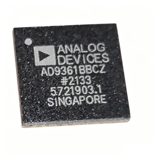
AD9361BBCZ - RF Agile Transceiver 70MHz-6GHz | Analog Devices
The AD9361BBCZ is a high performance, highly integrated radio frequency (RF) Agile Transceiver™ from Analog Devices, designed for 3G and 4G base station applications. It integrates dual transmitters and dual receivers, along with high-performance ADCs, DACs, frequency synthesizers, and digital signal conditioning blocks, into a single 144-ball CSPBGA package. Operating from 70 MHz to 6 GHz, it supports a wide range of wireless standards including LTE, WCDMA, and Wi-Fi. An RF transceiver is a device that combines a transmitter and receiver in a single package, sharing common circuitry. The AD9361 is a specific type of RF transceiver known as an RF Agile Transceiver, which offers wideband frequency coverage and programmability, making it suitable for software-defined radio (SDR) applications. It sits in the hierarchy of RF transceiver -> RF integrated circuit -> analog/mixed-signal IC -> semiconductor. Key features include a 2x2 transceiver architecture with 12-bit ADCs and DACs, a frequency range of 70 MHz to 6 GHz, and support for channel bandwidths from 200 kHz to 56 MHz. The device offers a high level of integration, reducing external component count and board space. It also features a configurable digital interface supporting CMOS and LVDS standards, and a flexible gain control scheme. Technically, the AD9361 uses a direct conversion architecture with integrated synthesizers and filters. It provides excellent linearity and noise performance, with a noise figure of 2 dB in the receive path and an error vector magnitude (EVM) of less than 1% for LTE signals. The device is programmable via a 3-wire or 4-wire SPI interface, allowing dynamic configuration of frequency, gain, and filtering. Typical applications include 3G/4G base stations, software-defined radios, military communications, and test and measurement equipment. Its wideband capability and programmability make it ideal for multi-standard, multi-band radios. The AD9361 is also used in MIMO systems and phased array radar. When designing with the AD9361, careful attention must be paid to power supply decoupling and PCB layout to achieve optimal RF performance. The device requires multiple supply rails, and proper grounding and shielding are essential to minimize noise and interference.
AD9361BBCZ-CSL - RF Agile Transceiver, 70MHz-6GHz | Analog Devices
The AD9361BBCZ-CSL is a high-performance, highly integrated RF Agile Transceiver from Analog Devices, designed for 3G and 4G base station applications. It operates over a frequency range of 70 MHz to 6 GHz and features a 2x2 transceiver architecture with integrated frequency synthesizers, making it ideal for a broad range of radio transceiver applications. The device is housed in a 144-ball CSPBGA package and is qualified for space applications, with radiation testing for Total Ionizing Dose (TID) effects and enhanced reliability for aerospace environments. An RF transceiver is a device that combines a transmitter and receiver in a single package, handling both the modulation/demodulation of signals and the conversion between RF and baseband frequencies. The AD9361BBCZ-CSL integrates the RF front end, mixed-signal baseband, and frequency synthesizers, simplifying design-in and reducing component count. This integration is part of a hierarchy: RF transceiver -> RF front end -> mixed-signal baseband -> frequency synthesizer -> radio communication system. Key features include a wide frequency range of 70 MHz to 6 GHz, support for channel bandwidths from 200 kHz to 56 MHz, and a 12-bit ADC/DAC resolution. The device offers programmable gain control, digital filtering, and a flexible digital interface supporting CMOS and LVDS standards. Its high level of integration eliminates the need for external VCOs and loop filters, reducing board space and design complexity. Technically, the AD9361BBCZ-CSL uses a direct-conversion architecture with integrated fractional-N synthesizers, achieving excellent phase noise and linearity. The device supports both FDD and TDD modes, making it versatile for various wireless standards. Its radiation-hardened design ensures reliable operation in space environments, with TID testing and enhanced screening. Typical applications include 3G/4G base stations, software-defined radios (SDR), military and aerospace communications, and point-to-point microwave links. The wide frequency range and programmability make it suitable for multi-band, multi-standard radios. When designing with this device, careful attention must be paid to power supply decoupling and PCB layout to maintain optimal RF performance. The device requires multiple supply rails and a clean reference clock for best results.
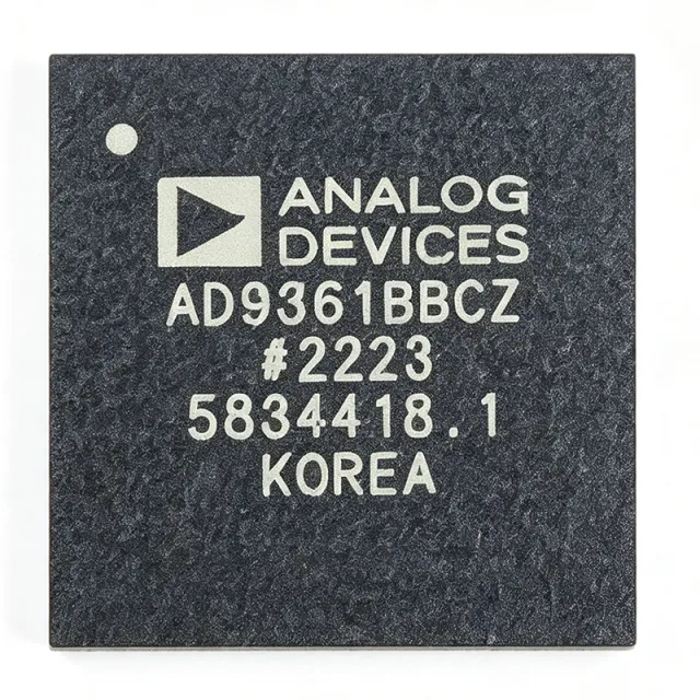
AD9361BBCZ-REEL - 70MHz-6GHz RF Agile Transceiver | Analog Devices
The AD9361BBCZ-REEL is a high performance, highly integrated radio frequency (RF) Agile Transceiver from Analog Devices, designed for 3G and 4G base station applications. It operates over a frequency range of 70 MHz to 6 GHz, covering a wide spectrum of cellular and other wireless standards. The device integrates a 2x2 transceiver architecture with configurable 12-bit CMOS/LVDS digital baseband interface, enabling flexible connection to baseband processors. Housed in a 144-ball CSPBGA package, it offers a compact solution for multi-band, multi-standard radio designs. An RF transceiver is a device that combines both a transmitter and a receiver, sharing common circuitry. The AD9361 is an agile transceiver, meaning it can be dynamically reconfigured to support different frequency bands, channel bandwidths, and modulation schemes. This flexibility makes it a key component in software-defined radio (SDR) systems, where the same hardware can adapt to various communication standards without redesign. The AD9361 sits at the heart of the RF front-end, bridging the antenna and the digital baseband processor, and is essential for modern wireless infrastructure. Key features include a frequency range of 70 MHz to 6 GHz, support for channel bandwidths from less than 200 kHz to 56 MHz, and a highly linear receiver with noise figure as low as 2 dB. The transmitter offers excellent error vector magnitude (EVM) performance, enabling high-order modulation schemes. The device also includes integrated fractional-N synthesizers, digital filters, and automatic gain control (AGC), reducing external component count and simplifying design. Technically, the AD9361 employs a direct conversion architecture with advanced calibration algorithms to mitigate I/Q imbalance and DC offset. It supports both FDD and TDD modes, and its programmable interface allows seamless integration with various baseband processors. The device operates from a 1.3V core supply and includes multiple power-down modes for efficient power management. Typical applications include 3G/4G base stations, small cells, software-defined radios, military communications, and test and measurement equipment. Its wide frequency range and programmability make it suitable for multi-band, multi-standard radio platforms. When designing with the AD9361, careful attention must be paid to power supply decoupling and PCB layout to achieve optimal RF performance. The device requires a clean 1.3V supply and proper grounding to minimize noise and interference.
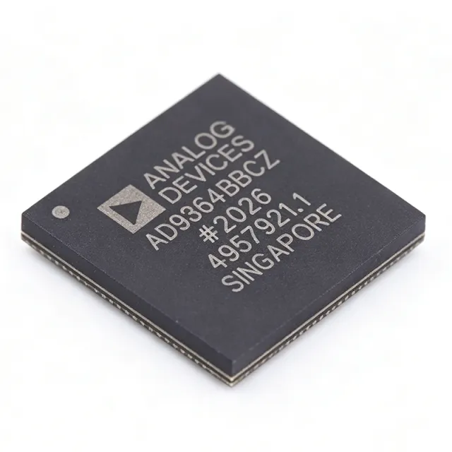
AD9364BBCZ - 70MHz-6GHz RF Agile Transceiver | Analog Devices
The AD9364BBCZ is a high-performance, highly integrated radio frequency (RF) Agile Transceiver™ from Analog Devices, designed for 3G and 4G base station applications. It operates from 70 MHz to 6.0 GHz, covering most licensed and unlicensed bands, and supports channel bandwidths from less than 200 kHz to 56 MHz. The device combines an RF front end with a flexible mixed-signal baseband section and integrated frequency synthesizers, simplifying design-in by providing a configurable digital interface to a processor. It is a 1x1 variant with 2 receive and 2 transmit paths, packaged in a 144-ball LFBGA/CSPBGA. An RF transceiver is a device that both transmits and receives radio frequency signals, integrating the RF front end, mixed-signal baseband, and frequency synthesis in a single IC. It sits between the antenna and the digital baseband processor in a communication system, converting RF signals to digital baseband and vice versa. The AD9364 is part of the RF Agile Transceiver family, which includes the AD9361 and AD9363, and is designed for software-defined radio (SDR) applications. Key features include wide frequency coverage (70 MHz to 6 GHz), programmable channel bandwidth (200 kHz to 56 MHz), integrated synthesizers, and a configurable digital interface. The device supports FDD and TDD modes, and includes auxiliary ADC/DACs for monitoring and control. Its high integration reduces external component count and board space, making it ideal for compact base station designs. The AD9364 uses a direct-conversion architecture with integrated filters and gain control, providing excellent linearity and sensitivity. It includes a dual-channel receiver and transmitter, with support for MIMO configurations when paired with multiple devices. The device is programmable via a 3- or 4-wire SPI interface, allowing dynamic reconfiguration of frequency, gain, and filter settings. Typical applications include 3G/4G base stations, software-defined radio, point-to-point microwave links, and test and measurement equipment. Its wide frequency range and bandwidth flexibility make it suitable for both licensed and unlicensed band operation. When designing with the AD9364, careful attention must be paid to power supply decoupling and RF layout to achieve optimal performance. The device requires multiple supply rails and a clean reference clock. Proper grounding and shielding are essential to minimize noise and interference.
AD9364BBCZ-REEL - 70MHz-6GHz RF Agile Transceiver | Analog Devices
The AD9364BBCZ-REEL is a high-performance, highly integrated RF Agile Transceiver™ from Analog Devices, designed for a broad range of wireless applications. It operates from 70 MHz to 6.0 GHz, covering most licensed and unlicensed bands, and supports channel bandwidths from less than 200 kHz to 56 MHz. The device integrates an RF front end, a flexible mixed-signal baseband section, and frequency synthesizers, simplifying design-in by providing a configurable digital interface to a processor. This 1x1 variant features one receive and one transmit channel, making it ideal for single-channel transceiver designs. An RF transceiver is a device that combines both a transmitter and a receiver in a single package, handling the modulation, demodulation, and frequency conversion of RF signals. It is a critical component in wireless communication systems, bridging the analog RF domain and the digital baseband processor. The AD9364 belongs to the RF Agile Transceiver family, which includes the AD9361 (2x2) and AD9363 (1x1, reduced bandwidth), all sharing a similar architecture and programming model. Key features of the AD9364 include a wide frequency range of 70 MHz to 6 GHz, support for channel bandwidths from 200 kHz to 56 MHz, and a configurable digital interface (CMOS/LVDS) for baseband connectivity. The device offers excellent receiver sensitivity and transmitter linearity, with an output power of 8 dBm. It also includes integrated fractional-N synthesizers, reducing external component count and simplifying frequency planning. Technically, the AD9364 employs a direct-conversion architecture with advanced calibration algorithms to minimize I/Q imbalance and DC offset. The device supports both FDD and TDD modes, making it versatile for various wireless standards. Its programmability allows dynamic reconfiguration of frequency, bandwidth, and gain, enabling software-defined radio (SDR) implementations. Typical applications include 3G/4G base stations, software-defined radios, portable test equipment, and military communications. The wide frequency range and bandwidth flexibility make it suitable for multi-standard radios that must operate across different bands. When designing with the AD9364, careful attention must be paid to power supply decoupling and clocking. The device requires multiple supply rails, and proper filtering is essential to achieve optimal performance. The digital interface should be configured for the appropriate voltage levels and data rate to match the baseband processor.
AD9371BBCZ - Dual RF Transceiver 300MHz-6GHz | Analog Devices
The AD9371BBCZ is a highly integrated, wideband RF transceiver from Analog Devices, designed for dual-channel transmitters and receivers with integrated synthesizers and digital signal processing functions. It operates over a frequency range of 300 MHz to 6 GHz, making it suitable for a wide variety of wireless applications. The device is packaged in a 196-ball LFBGA/CSPBGA (12 mm x 12 mm) and is part of the Mykonos family. An RF transceiver is a device that combines both a transmitter and a receiver in a single package, enabling bidirectional communication over radio frequencies. The AD9371 is a system-on-chip (SoC) that integrates the RF front-end, analog-to-digital converters (ADCs), digital-to-analog converters (DACs), and digital signal processing (DSP) blocks, reducing the need for external components and simplifying system design. It sits within the hierarchy of RF transceivers -> wideband transceivers -> software-defined radio (SDR) components. Key features include dual transmitters and receivers, support for TDD and FDD modes, and a digital interface that supports JESD204B serial data. The device offers high dynamic range and low power consumption, making it ideal for battery-powered and portable applications. It also includes an observation path for transmitter monitoring and calibration, enhancing system performance. Technically, the AD9371 integrates fractional-N synthesizers for local oscillator (LO) generation, reducing external LO circuitry. The device supports a maximum receiver bandwidth of 100 MHz and transmitter bandwidth of 250 MHz, enabling wideband operation. It operates from a 3.3V supply and includes power management features to optimize efficiency. Typical applications include software-defined radios, cellular base stations (3G/4G/5G), point-to-point microwave links, and military communications. Its wide frequency range and high integration make it a versatile choice for both commercial and defense systems. When designing with the AD9371, careful attention must be paid to power supply decoupling and thermal management, as the device dissipates significant power. The JESD204B interface requires proper clocking and synchronization to ensure data integrity.
AD9371BBCZ-REEL - Dual RF Transceiver 300MHz-6GHz | Analog Devices
The AD9371BBCZ-REEL from Analog Devices is a highly integrated, wideband RF transceiver designed for dual-channel transmitters and receivers, integrated synthesizers, and digital signal processing functions. Operating from 300 MHz to 6 GHz, this device supports a wide range of wireless communication standards, including 4G/5G cellular infrastructure, software-defined radio (SDR), and radar systems. The transceiver is housed in a 196-ball CSP_BGA package (12 mm × 12 mm), offering a compact solution for high-performance RF front-ends. An RF transceiver is a device that combines both a transmitter and a receiver in a single package, handling the modulation, demodulation, and frequency conversion of RF signals. In the hierarchy of wireless communication systems, an RF transceiver sits between the baseband processor and the antenna, converting digital baseband data to analog RF signals for transmission and vice versa for reception. The AD9371 integrates dual transmitters and receivers, along with observation and feedback paths, enabling advanced features like digital pre-distortion (DPD) and envelope tracking. Key features of the AD9371 include dual-channel transmitters and receivers, integrated synthesizers, and a digital signal processing block that supports various filtering and calibration functions. The device offers a high dynamic range and low noise figure, making it suitable for demanding applications. It also includes an observation receiver (ORx) path for DPD and a feedback path for transmit monitoring. The transceiver supports a wide frequency range, from 300 MHz to 6 GHz, covering most cellular and ISM bands. Technically, the AD9371 employs a direct-conversion architecture with advanced calibration algorithms to achieve high performance. It integrates fractional-N synthesizers for both transmit and receive paths, reducing external component count. The device operates from a 1.3 V core supply and 1.8 V I/O supply, with power dissipation typically around 5 W. The digital interface supports JESD204B, a high-speed serial interface standard, enabling efficient data transfer to FPGAs or ASICs. Typical applications include 4G/5G macro and small cell base stations, software-defined radios, phased array radar, and test and measurement equipment. The AD9371's wide frequency range and high integration make it ideal for multi-band, multi-standard systems where board space and power efficiency are critical. When designing with the AD9371, careful attention must be paid to power supply decoupling and thermal management. The device requires multiple supply rails, and proper filtering is essential to achieve the specified noise performance. The exposed pad on the CSP_BGA package should be soldered to a thermal via array to ensure adequate heat dissipation.
AD9375BBCZ - Dual RF Transceiver with DPD | Analog Devices
The AD9375BBCZ is a highly integrated, wideband radio frequency (RF) transceiver from Analog Devices, designed for 3G/4G/5G base stations and massive MIMO systems. It features dual-channel transmitters (Tx) and receivers (Rx), integrated synthesizers, a fully integrated digital predistortion (DPD) actuator and adaptation engine, and comprehensive digital signal processing functions. Operating from 300 MHz to 6 GHz, it supports a wide range of cellular and wireless standards. An RF transceiver is a device that combines both a transmitter and a receiver in a single package, sharing common circuitry. In the hierarchy of wireless communication systems, an RF transceiver is a key component within the RF front-end, which sits between the antenna and the baseband processor. It handles the conversion of RF signals to and from intermediate frequencies or baseband, enabling wireless communication. The AD9375 is a high-performance example, integrating DPD to enhance linearity and efficiency in power amplifiers. Key features include dual-channel operation, integrated DPD, and a frequency range of 300 MHz to 6 GHz. The device supports observation paths for DPD and includes digital signal processing functions such as filtering, gain control, and calibration. It is housed in a 196-ball LFBGA/CSPBGA package, suitable for compact base station designs. The integrated DPD engine reduces the need for external DPD components, simplifying system design and reducing bill of materials. Technically, the AD9375 uses a direct conversion architecture with high dynamic range and linearity. It includes multiple PLLs and synthesizers for flexible frequency planning. The DPD actuator and adaptation engine work together to correct power amplifier nonlinearities, improving system efficiency and reducing spectral regrowth. The device also supports MIMO configurations, making it ideal for advanced antenna systems. Typical applications include 3G/4G/5G base stations, massive MIMO systems, software-defined radios, and military communications. Its wide frequency range and DPD capability make it suitable for both FDD and TDD systems. When designing with the AD9375, careful attention must be paid to power supply decoupling and thermal management. The device requires multiple supply rails and a well-designed PCB layout to achieve optimal performance. The integrated DPD engine requires configuration and calibration, which can be done via the serial peripheral interface (SPI).