USB Interface ICs
بەرهەمەکان (37)

ADM211EAR - 5V RS-232 Transceiver, 28-SOIC | Analog Devices
The Analog Devices ADM211EAR is a 4-driver, 5-receiver RS-232 and V.28 interface transceiver designed for single-supply operation from +5 V. The device operates at data rates up to 200 kbps in the ADM211 family and is available in a 28-pin SOIC package. It is intended for communication links where a higher-voltage RS-232 supply is unavailable or inconvenient. An RS-232 transceiver is an interface integrated circuit that combines line drivers and receivers with the electrical conversion required for balanced-looking differential signaling over single-ended, bipolar RS-232 connections. The ADM2xxE family is positioned as a robust RS-232 and V.28 interface solution, with onboard charge-pump support and external 0.1 uF capacitors used for the RS-232 interface voltage generation. The ADM211EAR provides four RS-232 drivers and five receivers, allowing multiple channels and a full-duplex communications arrangement in one package. The manufacturer describes the ADM211 as a production part with a 200 kbps data rate, while the related ADM211E family is described as supporting rates up to 230 kbps. The device also provides shutdown and enable control functions in relevant family members, making it useful for systems that need controlled power states or interface isolation. Key application areas include industrial data acquisition, test and measurement equipment, POS terminals, industrial controls, and embedded systems communicating with legacy RS-232 peripherals. The +5 V supply requirement simplifies system design where the logic supply is already present and a separate ±12 V RS-232 supply is not practical. External charge-pump capacitors should be placed close to the relevant pins, and the receiver inputs should be protected from electrostatic discharge and excessive voltage excursions. When selecting this device, verify the exact driver and receiver count, enable and shutdown behavior, package suffix, and operating-temperature requirements against the Analog Devices ADM211 datasheet Rev. D. The 28-SOIC package is intended for conventional PCB assembly and offers a larger pin count than compact RS-232 interface packages. The ADM211EAR is therefore appropriate when a design needs several RS-232 channels from one +5 V supply and a standard SOIC footprint.

DS90C387VJD-TI - Dual Pixel LVDS Transmitter | Texas Instruments
Texas Instruments DS90C387VJD-TI is a +3.3 V dual-pixel LVDS display interface transmitter for SVGA and QXGA flat-panel systems. It converts 48 bits of CMOS/TTL dual-pixel color data into 8 LVDS differential data streams and transmits VSYNC, HSYNC, DE, and two user-defined control signals during blanking intervals. The device is associated with the DS90CF388 receiver in a host-to-flat-panel display link. A dual-pixel LVDS display interface, also called LDI, is a high-speed serial display-link technology that reduces the number of parallel signal traces required between a graphics host and a display panel. The DS90C387VJD-TI accepts parallel CMOS/TTL pixel data and converts it into low-voltage differential signaling, while the paired receiver reconstructs the data at the display end. This hierarchy places the device within interface ICs, display-interface transceivers, LVDS signaling, and semiconductor interface components. The principal feature set includes 48-bit dual-pixel input, eight LVDS output streams, support for SVGA and QXGA resolutions, and +3.3 V operation. The transmitter is intended for systems in which a display controller cannot directly drive the long, high-speed differential bus required between the host and flat-panel display. Its differential outputs are designed to support reliable transfer of pixel data across a cable or PCB connection while reducing signal-noise pickup relative to a single-ended interface. The DS90C387VJD-TI is a display transmitter rather than a general-purpose LVDS transceiver, and its clocking, data mapping, control-signal timing, and receiver pairing must be treated as a coordinated system. The 100-pin TQFP package provides the numerous data, control, power, and ground connections required by the dual-pixel architecture. Its surface-mount construction supports automated board assembly, while the dense pin count requires careful escape routing and controlled-length routing between the host and display interface. Typical applications include desktop flat-panel monitors, industrial HMI panels, medical display controllers, automotive display links, and other SVGA or QXGA systems that use the DS90C387 and DS90CF388 transmitter/receiver pairing. The interface is especially appropriate where a parallel host bus must be converted to a compact differential display connection across a larger physical distance. Designers should use the pin-description table and recommended decoupling arrangement in the Texas Instruments datasheet when assigning every signal and planning the power network. Differential LVDS pairs should be routed as tightly coupled pairs with controlled impedance, while the CMOS/TTL inputs require clean return paths and adequate settling time. Board-level validation should include power-up sequencing, blanking-period control signaling, data mapping, receiver synchronization, and compliance with the display timing requirements of the final panel system. This page combines the manufacturer product information with a practical view of system compatibility, package constraints, and display-link implementation considerations. It also distinguishes exact drop-in alternatives from family members that require different packages or interface functions, helping engineers avoid treating electrically similar LVDS devices as PCB-compatible replacements.

DS90C402MX/NOPB - Dual LVDS Receiver | Texas Instruments
The Texas Instruments DS90C402MX/NOPB is a dual low-voltage differential signaling receiver optimized for high data-rate and low-power point-to-point interfaces. It supports two LVDS receiver channels, a maximum data rate of 155.5 Mbps, a 4.5 V to 5.5 V supply range, and an 8-pin SOIC package. Its ±100 mV differential input threshold and common-mode noise protection improve receiver performance in systems where signal integrity matters. An LVDS receiver is an interface circuit that converts a small differential voltage into a compatible digital logic signal. LVDS belongs to the differential-signal interface family and is commonly positioned between a high-speed transmitter and downstream digital circuitry. The DS90C402 receiver works with the DS90C401 transmitter to form a complete high-speed point-to-point link. This architecture reduces signal amplitude while preserving noise immunity compared with many single-ended interfaces. The DS90C402MX/NOPB provides a dual-receiver configuration in an 8-pin SOIC, allowing two data channels to share one device. Its 155.5 Mbps maximum data rate supports legacy point-to-point links that may appear in industrial control, telecommunications, test equipment, and embedded systems. A 4.5 V minimum supply supports 5 V interface designs, while the 5.5 V maximum accommodates standard 5 V supply tolerances. The receiver's ±100 mV threshold sensitivity defines the differential signal amplitude required for reliable detection. Common-mode noise protection helps separate the intended differential signal from voltage disturbances shared by both conductors. Because LVDS depends on balanced routing and controlled termination, the receiver itself does not eliminate the need for proper PCB geometry, characteristic-impedance control, and connector or source termination. Typical applications include dual-channel point-to-point backplanes, industrial data links, telecommunications equipment, instrumentation, and embedded control systems. The DS90C402 is especially appropriate when two receive channels are needed near one another and a compact 8-pin SOIC is preferred over larger receiver packages. Pairing it with the DS90C401 provides a matched transmitter and receiver solution for a bidirectional or paired communication path. PCB layout should keep the LVDS traces short, continuous, and matched in geometry, with a solid ground plane providing the return path. Place termination components at the appropriate transmitter or receiver endpoint, and avoid stubs or test-point structures that create impedance discontinuities. Decoupling capacitors should connect directly to the device power and ground pins to minimize supply-loop inductance. This page combines manufacturer specifications, ordering information, drop-in replacement guidance, comparison data, and practical interface-layout guidance. It supports faster component selection for engineers designing a 155.5 Mbps LVDS link while highlighting the electrical and package conditions required for true PCB-level substitution.

DS90CR215MTD - 21-Bit 66MHz LVDS Transmitter | Texas Instruments
The Texas Instruments DS90CR215MTD is a 3.3 V, rising-edge data-strobe LVDS transmitter for parallel-to-serial data transfer, supporting 21 bits at up to 66 MHz in a 48-TSSOP package. The device is intended for point-to-point links that require low-voltage differential signaling, a dedicated clock strobe, and compact digital-interface conversion. An LVDS transmitter, also called an LVDS driver, converts low-voltage digital signals into a balanced differential pair. This differential signaling method improves noise immunity by rejecting common-mode noise and allowing the receiver to detect smaller voltage differences. In the DS90CR215, the data-strobe architecture carries 21 data bits together with a clock signal, placing the transmitter within the parallel-interface and serial-link hierarchy of communication ICs. Principal characteristics include 3.3 V operation, 21-bit parallel data handling, a 66 MHz maximum signaling rate, and a 48-TSSOP package. The manufacturer identifies the device as a rising-edge data-strobe LVDS interface IC. Its operating temperature range extends from -40 °C to +85 °C, supporting industrial-temperature equipment. The package is intended for surface-mount assembly and provides a relatively high pin count for the parallel data and differential output connections. The DS90CR215MTD is designed for systems in which a processor, FPGA, display controller, or data acquisition engine must communicate over a fast, noise-resistant differential link. Because the link uses balanced signaling, it can operate in environments containing switching equipment, long internal cable runs, or multiple high-speed digital sources where single-ended routing would be more susceptible to interference. Typical uses include industrial control cabinets, test and measurement systems, medical monitoring equipment, instrumentation, video-processing modules, and embedded data acquisition. The 66 MHz channel-link rate supports high-throughput point-to-point transfers, while the 21-bit parallel interface reduces the number of package pins required for data compared with a fully serialized interface. Matching receiver characteristics and controlled trace geometry remain important for reliable operation. For PCB design, treat the differential data and clock outputs as controlled-impedance nets, place the device close to the connector or receiving interface, and route the differential pair as a matched pair without plane splits or excessive stubs. Verify power and ground distribution, follow the manufacturer's decoupling recommendations, and confirm that the receiver and cable meet the link's timing and termination requirements. This page consolidates the manufacturer's product characteristics, package information, operating limits, sourcing links, and practical interface guidance into one engineering reference. It also highlights the limited availability of verified pin-compatible substitutes and distinguishes exact lead-finish variants from parts that cannot replace the transmitter function.
DS90CR216MTD - 21-Bit 66 MHz LVDS Receiver | TI
The Texas Instruments DS90CR216MTD is a 3.3 V rising-edge data-strobe LVDS receiver for a 21-bit Channel Link interface operating up to 66 MHz, housed in a 48-pin TSSOP package. It accepts three differential data pairs plus a differential clock pair, returning 21 parallel data bits and one clock in a serialized-to-parallel interface commonly used for high-speed backplane and inter-board communication. A Channel Link receiver is a low-voltage differential signaling receiver that recovers parallel logic data from a serialized LVDS link. Its position in the signal chain is transmitter, twisted-pair cable, receiver, and parallel logic destination. By multiplexing up to 21 data lines plus one clock onto as few as nine conductors, the interface reduces cable width while preserving the noise immunity associated with differential signaling. The device's principal features include a 21-bit parallel output, a 66 MHz maximum signaling rate, 3.3 V operation, LVDS-compatible differential inputs, and rising-edge data strobe. The 48-pin TSSOP package provides a practical surface-mount footprint for systems where cable reduction and low-voltage differential signaling are more important than minimizing connector count. The DS90CR216 is designed for point-to-point links carrying serialized data between boards, backplanes, or rack-mounted equipment. Its 3:1 multiplexing architecture reduces the number of transmission lines relative to a conventional parallel bus while retaining a differential clock lane. The receiver's separate data and clock outputs allow the receiving logic to capture the recovered data using the supplied clock signal. Typical applications include industrial control systems, test equipment, instrumentation racks, high-speed backplanes, video-processing modules, and embedded communication links. Because the interface is voltage-based rather than a current-mode driver topology, board designers should treat the LVDS input routing as a controlled-impedance transmission-line problem and maintain a continuous return path beneath the pair. The primary design consideration is signal integrity. Route each differential pair as a tightly coupled pair over a controlled-impedance board, keep stub lengths short, and place receiver termination close to the device pins. Confirm the cable length, connector loss, and receiver tolerance against the channel-link operating limits before releasing a multi-board system. This page combines manufacturer family information, package and interface details, sourcing links, replacement analysis, and practical LVDS layout guidance to help engineers evaluate the DS90CR216MTD for 21-bit channel-link systems.

DS90LV019TMTCX - 3.3V/5V LVDS Transceiver | Texas Instruments
The Texas Instruments DS90LV019TMTCX is a 3.3 V or 5 V LVDS driver and receiver capable of 100 Mbps point-to-point signaling in a 14-pin TSSOP package. It translates single-ended TTL-compatible logic into Low Voltage Differential Signaling and converts the differential input back to TTL levels. An LVDS transceiver is a high-speed interface device that combines a differential line driver, a differential receiver, and associated biasing or termination functions. Within the interface hierarchy, it belongs to the line-driver and receiver class, then to LVDS interface ICs, and ultimately to the broader semiconductor category. Differential signaling reduces sensitivity to common-mode noise because the receiving circuit evaluates the voltage difference between two conductors rather than the voltage referenced to ground. The device supports both 3.3 V and 5 V operation, provides one transmit and one receive path, and uses a flow-through pin arrangement that supports short PCB routing between logic and differential pins. According to the Texas Instruments product page, the DS90LV019 is intended for high-speed, low-power point-to-point interconnects. Its operating temperature range is -40 °C to +85 °C. The DS90LV019 uses current-mode differential signaling to keep power dissipation controlled at higher data rates. Cross-reference information reports a 3.5 mA output loop current and a 0.45 V differential output level. The receiver converts the differential LVDS input into a single-ended TTL-compatible output, allowing the same device to bridge a TTL source and an LVDS link. Typical uses include clock distribution, point-to-point data links, telecom equipment, industrial controllers, test and measurement systems, and embedded backplane interconnects. The 14-pin TSSOP package is suitable for compact multilayer PCB designs where a conventional dual-row surface-mount footprint is preferred over larger leaded packages. For reliable LVDS operation, place the differential pair on a controlled-impedance PCB layer, keep the two traces closely coupled, terminate the receiver as recommended by the manufacturer, and avoid routing the pair through noisy power or switching regions. Confirm the board's trace impedance and connector or cable loss before selecting a long cable or high data rate. This page consolidates manufacturer specifications, distributor package information, verified drop-in cross-references, interface-comparison parameters, and practical PCB guidance so engineers can evaluate the DS90LV019TMTCX as a complete LVDS interface solution.
MAX13487EESA+T - 5V RS-485/RS-422 Transceiver | Maxim Integrated
The Analog Devices (Maxim Integrated) MAX13487EESA+T is a +5V half-duplex RS-485/RS-422-compatible transceiver with ±15kV ESD protection, proprietary AutoDirection control, and 500 kbps data rate, housed in an 8-pin NSOIC (SOIC-8, 3.90mm width) package with one driver and one receiver. An RS-485/RS-422 transceiver is a differential interface IC that converts single-ended logic signals into differential bus signals, sitting within the interface IC hierarchy of serial communications semiconductors. Half-duplex RS-485 transceivers share one differential pair for both transmit and receive, so direction control is a key architectural decision. Traditional parts require a microcontroller GPIO to drive the DE/RE pins; the MAX13487E instead uses Maxim's AutoDirection architecture, which senses the driver input and enables the driver automatically. Key features include true fail-safe receiver circuitry guaranteeing a logic-high receiver output when inputs are shorted, open, or idle, hot-swap capability that eliminates false transitions on the bus during power-up or live insertion, and ±15kV ESD protection on the transceiver pins. The /SHDN pin reduces supply current for low-power systems, and /DI, /RE and /SHDN pins are rated from -0.3V to +6V, allowing direct interfacing with 3.3V microcontrollers without level shifting. Architecturally, the device integrates one driver and one receiver operating from a +5V supply, with receiver input being 1/8 unit load, permitting up to 256 transceivers on a shared bus (per Cosine reference to equivalent-class devices). AutoDirection removes firmware overhead and timing errors associated with GPIO direction switching in polled half-duplex protocols. Typical applications include industrial fieldbus and Profiling nodes, building automation and HVAC controllers, motor/drive networks, battery-management stacks, and embedded metering where robust differential communication over long cables is required. Design consideration: the hot-swap feature matters when nodes are inserted into a live backplane; for software-controlled designs a conventional DE/RE part may be preferred instead. Verify bus biasing resistors for idle-state fail-safe operation. This page synthesizes distributor availability data, cross-reference findings, and practical design notes not found in the manufacturer datasheet alone.

MAX14819AATM+T - Dual IO-Link Master Transceiver | Analog Devices
The Analog Devices (formerly Maxim Integrated) MAX14819AATM+T is a low-power, dual-channel IO-Link master transceiver with integrated sensor/actuator power-supply controllers, housed in a 48-pin LFCSP (TQFN) 7x7 mm package. The device integrates two IO-Link physical layers, two L+ supply controllers, two auxiliary digital input channels, and framers/L+ drivers compliant with IO-Link v1.1.3, IEC 61131-2, and IEC 61131-9 SDCI standards. An IO-Link master transceiver is a type of industrial communication controller that bridges a higher-level fieldbus (e.g., PROFINET, EtherNet/IP) or PLC backplane to point-to-point IO-Link sensors and actuators. Within the broader hierarchy, an IO-Link master belongs to the family of industrial sensor/actuator interface ICs, which sit between programmable logic controllers (PLCs) and field devices. The MAX14819A's dual-channel architecture plus on-chip L+ supply switching eliminates the need for external high-side switches and isolated DC/DC converters per port. Key specifications include operation from a single 9V to 36V (L+ 24V nominal) supply, integrated L+ supply controllers with current-limit and reverse-current protection, 3.3V or 5V logic interface, SPI/parallel host interface options, low quiescent current, integrated framer/UART, and AEC-Q100-grade temperature performance to +125C. Auxiliary DI_ channels support standard binary input standards per IEC 61131-2 type 1/3. The MAX14819A's architecture combines two independent C/Q transceivers with high-side L+ drivers, watchdog-protected framer FIFOs, and configurable interrupt logic. Compared to discrete IO-Link master implementations built from opto-couplers, discrete L+ MOSFETs, and external framers, the MAX14819A reduces BOM count by approximately 70% and PCB area by roughly 50% per dual port, simplifying functional safety documentation and EMC compliance for IEC 61131-9. Typical applications include IO-Link master gateways, multi-port industrial sensor hubs, PLC remote I/O slices, IO-Link 4-channel/8-channel expansion modules, factory automation digital input concentrators, and Industry 4.0 retrofit I/O modules. Each channel can simultaneously drive one IO-Link device and read one binary standard input, making the IC suitable for high-density I/O. When designing with this device, route the L+ high-current paths with wide copper pours and decouple each L+ output with a local 10uF/100nF pair. Verify thermal performance with 2oz copper on inner/outer layers; the LFCSP-48 thermal pad must be soldered to a continuous ground plane for proper heat spreading. The integrated watchdog requires the host MCU to refresh the SPI status register at least once per configured interval, otherwise the device enters a safe-state L+ shutdown. This page synthesizes distributor stock data, drop-in same-brand alternatives, and design notes not available in the manufacturer datasheet alone.

MAX14882AWE+ - 5kVRMS Isolated CAN Transceiver, 16-SOIC | Analog Devices
The Analog Devices MAX14882AWE+ is an isolated high-speed CAN transceiver providing 5kVRMS (60s) galvanic isolation between the CAN-protocol controller-side (TDX, RXD) and the physical CAN bus wires (CANH, CANL), housed in a 16-pin Wide SOIC (W SOIC) package with 8mm of creepage and clearance. Key parameters include: ±25V receiver input common-mode range exceeding the ISO 11898 requirement of -2V to +7V, ±54V fault tolerance on CANH/CANL bus pins, and ±15kV ESD protection (Human Body Model) on bus-side GNDB. An isolated CAN transceiver is a physical-layer interface device that integrates galvanic isolation directly between the digital logic side and the bus side of a CAN (Controller Area Network) controller, replacing discrete optocouplers or digital isolators plus a separate CAN transceiver. The category hierarchy is: CAN transceiver -> CAN interface IC -> interface IC -> power management/isolation IC -> semiconductor. The MAX14882 reduces BOM count, simplifies PCB layout, and ensures deterministic propagation delay across the isolation barrier compared with discrete isolation + transceiver solutions. Key differentiating features include a wide 3.0V to 5.5V supply on the controller-side (VDDA) and 4.5V to 5.5V on the bus-side (VDDB), an integrated transformer driver and LDO that can power the bus-side supply from a single external transformer, and an auxiliary LDO capable of 130mA internal plus external load current up to 300mA total. Additional protection features include hot-plug detection, common-mode stabilization via POL pin, and the ability to recover from cross-wired bus cables through polarity inversion via the POL pin. The MAX14882 uses Analog Devices' proprietary capacitive isolation technology to achieve up to 5000VRMS isolation for 60 seconds while supporting data rates up to 1Mbps per ISO 11898. The integrated transformer driver eliminates the need for a dedicated isolated DC-DC converter, saving both PCB area and cost in space-constrained industrial designs. Typical applications include industrial CAN bus networks, factory automation systems, building automation (BACnet), photovoltaic inverter communications, electric vehicle charging stations, and any application where high-voltage ground potential differences exist between CAN nodes. When designing with this device, ensure the external transformer meets the 5kVRMS isolation rating and that creepage/clearance distances comply with end-application safety standards (IEC 61800, IEC 60664). Decoupling capacitors must be placed close to both VDDA and VDDB pins to minimize switching noise on the bus-side supply. This page synthesizes distributor pricing, drop-in alternatives, and practical design notes not found in the standalone manufacturer datasheet. All comparison data was sourced from real-time distributor listings on 2026-10-09.

MAX202EUE+ - 5V RS-232 Transceiver 2/2 TSSOP-16 | Analog Devices
The Analog Devices MAX202EUE+ is a +5V-powered RS-232 transceiver with 2 drivers and 2 receivers, housed in a 16-pin TSSOP package, requiring only four 0.1uF external capacitors and supporting data rates up to 120kbps. An RS-232 transceiver is a line driver and receiver IC that converts logic-level serial signals (TTL/CMOS, 0V to 5V) to the higher voltage EIA/TIA-232E levels (+/-5V or greater) required by serial communication ports, and converts incoming RS-232 levels back to logic levels. It sits within the interface IC family of the broader semiconductor taxonomy, bridging a microcontroller UART and a physical DB-9 serial port without needing +/-12V supplies. Key features include single +5V operation, which eliminates the dual supply rails older RS-232 interfaces required; dual charge-pump voltage converters that generate the RS-232 signaling levels from the 5V rail using only small 0.1uF flying and storage capacitors; and the E-suffix enhanced ESD protection family design intended for harsh industrial environments. The MAX202E family also uses a proprietary low-dropout transmitter output stage that maintains required +/-5V minimum EIA/TIA-232E output levels even at full load. According to Analog Devices, the drivers and receivers meet all EIA/TIA-232E and CCITT V.28 specifications at data rates up to 120kbps when loaded, and the drivers sustain +/-5V output swings at data rates in excess of 120kbps under the specified EIA/TIA-232E loading. The MAX202E/MAX232E devices are offered in 16-pin TSSOP, narrow SO, wide SO, and DIP packages, giving designers footprint flexibility across a common pinout. Typical applications include legacy industrial serial links (PLC and instrumentation ports), point-of-sale terminals and printers, set-top box and modem debug UARTs, and any embedded system that must interoperate with a standard RS-232 COM port. The dual-driver, dual-receiver configuration covers the TX/RX plus RTS/CTS handshake lines of a full serial port. Design consideration: place the four 0.1uF charge-pump capacitors and the V+ / V- storage capacitors close to the IC pins; ceramic X7R capacitors are recommended, and excessive ESR on C1/C2 degrades charge-pump efficiency and output swing. This page adds value beyond the manufacturer datasheet by consolidating drop-in alternative cross-references, ESD-grade family comparisons, practical layout guidance, and sourcing information in one place.

MAX3232EIPWG4 - Dual RS-232 Transceiver 250kbps | TI
The Texas Instruments MAX3232EIPWG4 is a 3-V to 5.5-V multichannel RS-232 line driver/receiver with dual drivers and dual receivers, 250 kbps data rate, and +/-15-kV IEC ESD protection, housed in a 16-pin TSSOP (PW) package rated from -40C to +85C. An RS-232 line driver/receiver is an interface transceiver that converts logic-level UART signals (TTL/CMOS, 0 V to VCC) into the higher-voltage RS-232 signal levels defined by TIA/EIA-232-F (+/-5 V minimum) and back again. It sits in the physical layer of the serial-communication hierarchy - below protocols such as UART framing - and within the broader family of line drivers, bus transceivers, and interface ICs. Because RS-232 levels exceed the supply rail, these devices integrate charge-pump voltage converters that generate the required positive and negative rails from a single low-voltage supply. Key features of the MAX3232E include operation from a single 3.0 V to 5.5 V supply, a proprietary low-dropout transmitter output stage delivering true RS-232 performance from 3.3 V and 5 V rails, dual charge pumps requiring only four small 0.1 uF external capacitors, and 250 kbps minimum data rate. ESD protection is rated at +/-15 kV (IEC 61000-4-2 air-gap), +/-8 kV (IEC 61000-4-2 contact discharge), and +/-15 kV human-body model on the RS-232 bus pins. Architecturally, the device uses two charge-pump stages (voltage doubler and inverter) with external flying and reservoir capacitors to synthesize approximately +/-5.5 V transmitter supplies from the VCC rail. The transmitter outputs meet or exceed TIA/EIA-232-F and ITU V.28 requirements and are protected against unlimited +/-15 V simultaneous shorts, while receivers keep the input threshold compatible with legacy 5 V logic. Typical applications include industrial process-control serial links, point-of-sale terminals and barcode scanners, battery-powered instrumentation using the low 0.3 mA typical supply current, and legacy DB9 COM-port interfacing for microcontrollers such as MSP430 and STM32. When designing, use 0.1 uF charge-pump capacitors placed within 10 mm of the device, and remember the receivers remain active even when transmitters are tri-stated. This page synthesizes distributor pricing, drop-in alternatives, pinout data, and practical design notes not found in the manufacturer datasheet, as of 2026-09-11.

MAX3243CPWRE4 - 3:5 RS-232 Transceiver | Texas Instruments
The Texas Instruments MAX3243CPWRE4 is a 3:5 multichannel RS-232 line driver and receiver operating from a 3 V to 5.5 V supply. It supports data rates up to 250 kbps, provides three driver and five receiver channels, and includes plus or minus 15 kV human-body-model ESD protection on the interface pins. The device is offered in a 28-pin TSSOP package. A multichannel RS-232 transceiver is an interface IC that combines the electrical drivers and receivers required to connect a low-voltage digital system to an RS-232 port. Within the interface hierarchy, it is both a line transceiver and a multichannel RS-232 interface IC. Its mixed driver-and-receiver arrangement supports equipment designs that need more receive channels than transmit channels, such as data acquisition, industrial control, test equipment, and multiport communications systems. Key features include a 3 V to 5.5 V operating range, 250 kbps maximum signaling rate, three drivers, five receivers, and plus or minus 15 kV ESD protection rated to the human-body-model test method. The 28-pin TSSOP package provides a compact surface-mount footprint, while its gull-wing terminal arrangement supports automated assembly and conventional PCB routing. The MAX3243 family uses charge-pump-assisted interface circuitry to generate the RS-232 bipolar voltage levels required by the standard. This allows the host-side logic to operate from a single 3 V or 5 V supply rather than requiring a separate negative rail for the RS-232 drivers. The transmitter handles the voltage translation and signal shaping, while the receiver converts the bipolar RS-232 input into a logic-compatible signal. Typical uses include industrial serial controllers, programmable-logic-interface equipment, data loggers, point-of-sale terminals, test-and-measurement instruments, and embedded systems that connect a TTL or CMOS serial port to an RS-232 bus. The five receiver channels also make the device suitable for monitoring multiple inbound RS-232 signals, including modem-control or status lines. The obsolete ordering code MAX3243CPWRE4 should not be used for new production releases without confirming an authorized supply route. For new designs, select the currently supported ordering option from the MAX3243 family and confirm the commercial temperature requirement, package fit, and availability before layout release. This page consolidates the manufacturer device description, lifecycle information, package details, interface characteristics, and verified cross-reference findings. It also provides engineering guidance on supply-voltage design, ESD protection, logic compatibility, and the practical differences between current family members and the obsolete original ordering code.

MAX3243ECAI+TG1Z - 3V RS-232 Transceiver | Analog Devices
Analog Devices MAX3243ECAI+TG1Z is a 3-driver, 5-receiver RS-232 interface transceiver designed for 3V-powered serial communications. The device operates from 3.0V to 5.5V, supports data rates up to 120 kbit/s, and is housed in a 28-pin SSOP package. Its AutoShutdown feature reduces supply current to 1 µA when no valid receiver signal is present, while enhanced electrostatic-discharge protection helps protect ports exposed to cable transients. An RS-232 transceiver is an interface IC that converts logic-level signals into RS-232 voltage levels and converts incoming RS-232 signals back into logic-compatible levels. It belongs to the line-driver and line-receiver hierarchy, connecting UART, microprocessor, or industrial-control logic to a cable-based serial port. The MAX3243 family is particularly useful when a design requires more than the standard two-transmitter, two-receiver arrangement and also needs low-power standby operation. Key features include three active drivers, five receivers, and one always-active receiver intended for external monitoring. The 3.0V to 5.5V supply range supports both 3.3V and 5V systems. Automatic shutdown and wakeup reduce power when the connected equipment is inactive, while the always-active receiver permits monitoring without keeping the main transmitter circuitry powered. The 120 kbit/s data rate covers legacy RS-232 equipment and industrial serial links. The MAX3243 uses charge-pump circuitry to generate the bipolar voltage levels required by RS-232 while operating from a single low-voltage supply. Its enhanced ESD protection is intended for interfaces connected to external cables, where electrostatic discharge and switching transients are more likely than on internal logic nets. Because the interface is not a differential communications standard, cable length, grounding, termination, and data direction must be considered during system integration. Typical uses include industrial control consoles, laboratory equipment, POS terminals, printers, data-acquisition systems, and service interfaces. The five-receiver arrangement can support several incoming RS-232 connections, while the three drivers support outgoing channels. The always-active monitoring receiver is useful in systems that must detect a remote or peripheral status signal even when automatic shutdown has disabled the normal receiver bank. Place the device close to the connector and route the exposed driver and receiver pins directly to the protected interface boundary. Keep logic-side traces away from cable-side pins, provide a stable ground reference, and follow the manufacturer application guidance for bypass capacitors and charge-pump capacitors. Verify signal polarity, direction, and shutdown behavior in firmware because these details determine how the transceiver should be enabled during communication. This product page combines the manufacturer family description with package-specific identification, practical interface design guidance, selection criteria, and a verified list of drop-in alternatives. It is intended to help engineers confirm supply compatibility, understand receiver and driver assignments, and determine whether the MAX3243 feature set fits a particular RS-232 design before layout release.
MAX3243ECPWG4 - 3/5 RS-232 Transceiver 28-TSSOP | Texas Instruments
Texas Instruments MAX3243ECPWG4 is a 3-to-5.5-V multichannel RS-232 line driver/receiver with 3 drivers, 5 receivers, and ±15-kV IEC ESD protection in a 28-pin TSSOP package. The device is designed for equipment that needs multiple RS-232 ports while operating from a single 3-V or 5-V supply. Its listed data rate is 500 kbps, and the operating temperature grade is commercial, 0°C to 70°C. An RS-232 transceiver combines the electrical interface functions required by a serial communications port. The driver section translates digital logic levels into RS-232 line signals, while the receiver section converts incoming line signals into logic-compatible outputs. A multichannel device such as the MAX3243ECPWG4 supports three driver channels and five receiver channels, allowing a system to implement several serial links without using separate single-channel transceivers. The family is commonly positioned for point-to-point RS-232 equipment, industrial control interfaces, and legacy peripheral connections. The MAX3243E family supports supply voltages from 3 V to 5.5 V, making it suitable for systems with 3.3-V or 5-V digital rails. The device includes ±15-kV IEC ESD protection on its external RS-232 connections, helping protect interface circuitry when cables are connected to user-accessible equipment. The MAX3243ECPWG4 is specified in a 28-TSSOP package with a 4.40-mm body width, and the commercial temperature range covers 0°C to 70°C. Use the manufacturer datasheet and package drawing to confirm the exact pin functions, exposed-pad arrangement, decoupling requirements, and recommended external charge-pump capacitors. The MAX3243E family operates as a multichannel RS-232 interface rather than as a voltage regulator or logic IC, so its power, ground, and signal connections should follow the device-specific application circuit. Request a quote through the XAIPART Request a Quote form for current commercial sourcing information. This page summarizes the device's RS-232 interface role, key electrical ratings, package information, and practical design considerations. It also distinguishes the obsolete MAX3243ECPWG4 ordering code from available family members and drop-in candidates, helping engineers make a controlled replacement decision rather than relying on package similarity alone.
MAX3243EIPWE4 - 3/5 RS-232 Transceiver | Texas Instruments
Texas Instruments MAX3243EIPWE4 is a 3-to-5.5 V multichannel RS-232 line driver and receiver with three drivers, five receivers, 250 kbps operation, and ±15 kV ESD protection in a 28-pin TSSOP package. It provides the physical-layer interface between RS-232 cable signals and TTL or CMOS-compatible logic used by embedded and industrial equipment. An RS-232 transceiver is an interface IC that converts between single-ended, bipolar RS-232 voltage levels and the lower-voltage logic levels used by digital circuits. The MAX3243 belongs to the broader line-driver and receiver hierarchy, combining three transmit channels with five receive channels in one device. Its multichannel arrangement allows one package to support several serial ports or a mixture of host and peripheral connections while reducing the number of interface components on the PCB. The MAX3243EIPWE4 operates from a 3 V to 5.5 V supply, making it suitable for systems using either 3.3 V or 5 V logic. Its stated maximum data rate of 250 kbps addresses conventional RS-232 links used by embedded controllers, test equipment, industrial controls, and point-of-sale systems. ±15 kV electrostatic-discharge protection helps improve robustness on connector-adjacent circuits where cables can expose equipment to electrostatic discharge. The industrial temperature grade, rectangular gull-wing TSSOP-28 package, and 28 terminals make the device appropriate for leaded-surface-mount industrial assemblies. Operating from a 3 V to 5.5 V supply also allows logic-level sharing with modern microcontrollers and programmable controllers. The three-driver and five-receiver arrangement can conserve board area compared with separate one-channel line-driver and receiver packages when several RS-232 signals must be handled. When designing the interface, connect each driver to the appropriate RS-232 TX and receiver to the RS-232 RX lines, then keep logic-side signals within the supply voltage. Place the required charge-pump capacitors and interface-network components according to the manufacturer datasheet. Route the exposed connector and cable paths away from sensitive logic, and provide the specified ESD-protection network where the transceiver is not adjacent to the connector. For reliable operation, verify that the selected UART supports the required 250 kbps line rate and that the cable length and baud rate satisfy RS-232 practice. Ensure power sequencing does not enable the interface before its logic supply is stable. This page compares the MAX3243EIPWE4 with documented alternatives and summarizes package, channel-count, speed, protection, and supply considerations for faster engineering selection.
P82B96TD/S410,118 - Dual I2C Bus Buffer 400kHz | NXP
The NXP Semiconductors P82B96TD/S410,118 is a dual bidirectional bus buffer IC that creates a non-latching, bidirectional logic interface between the standard I2C-bus and a wide range of other bus configurations, housed in an 8-pin SOIC (SOT96-1) surface-mount package. It operates at data rates up to 400 kHz, supports bus voltage levels from 3 V up to 15 V, and enables reliable I2C communication over bus lines up to 40 m in length. A bus buffer (also called an I2C repeater, level shifter, or bus extender) is an interface IC that isolates and strengthens signal lines in a serial communication system. In the hierarchy of I2C system components, it sits between the I2C master/slave devices and the physical bus, solving problems such as bus capacitance limits, mixed-voltage domains, and long cable runs that a plain two-wire I2C-bus cannot tolerate. The P82B96 belongs to the broader family of interface ICs - signal buffers, repeaters, and redrivers. Key features of the P82B96 include two independent buffer channels that handle both SCL and SDA I2C signals, bidirectional data transfer without latching, and a unique split of each I2C signal into forward and reverse (Tx/Ty and Rx/Ry) signal paths. According to NXP product information, it can interface I2C-bus logic signals to 350 uA SMBus systems, to 3.3 V logic devices, and to 15 V levels and/or low-impedance lines. The bipolar (bipolar transistor) process technology gives it robust drive strength and wide supply tolerance compared with typical CMOS buffers. Technically, each channel presents three ports: a logic-level side for standard I2C systems, and two additional ports that allow level translation between different voltage domains and drive of low-impedance or heavily loaded lines. Because the device is non-latching, it does not suffer from the lock-up issues common to some I2C repeater designs during arbitration or clock stretching. Typical applications include I2C bus extension over long cables (up to 40 m), mixed-voltage interfacing between 3.3 V and 15 V bus segments, SMBus systems, and driving multiple heavily loaded I2C branches in industrial and automotive bodies-electronics environments. A key design consideration: because the buffer passes drive current, the pull-up resistor values on each bus segment must be calculated independently for each side of the buffer rather than for the whole bus. This page synthesizes distributor pricing, drop-in alternatives, pinout data, and practical design notes not found in the manufacturer datasheet.
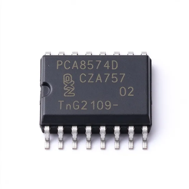
PCA8574D - 8-Bit I2C I/O Expander 400kHz SO16 | NXP
The NXP Semiconductors PCA8574D is a remote 8-bit I/O expander for the I2C-bus with interrupt output, housed in a 16-pin SO16 (SOIC) package. It operates from a 2.3 V to 5.5 V supply, supports a 400 kHz fast-mode I2C interface, and provides eight quasi-bidirectional GPIO ports with three hardware address pins (A0-A2) allowing up to eight devices on one bus. An I/O expander is a peripheral IC that increases the number of general-purpose input/output pins available to a microcontroller over a serial bus. In the power-management and interface hierarchy, the PCA8574D sits between the host MCU and external loads or switches: it belongs to the I2C GPIO expander family, which itself is part of the broader interface IC and remote peripheral category. Expanders save PCB traces, connector pins, and MCU pin budgets in pin-constrained designs. Key features include quasi-bidirectional I/O ports that can be independently assigned as inputs or outputs without a direction register, a latched interrupt output (INT) that flags any input change, totem-pole output capability via the open-drain INT pin, and direct LED driving with 25 mA sink capability per the datasheet family description. The three hardware address pins allow eight PCA8574 devices, or eight each of PCA8574 and PCA8574A, on the same I2C bus - up to 128 I/Os total. Architecturally, the PCA8574D uses a simple register-less command structure: the last written byte defines the port state, and a read returns port pin levels. Power-on reset initializes all ports high (quasi-bidirectional input mode), enabling simple push-button and key-matrix reads without software initialization. Typical applications include keypads and push-button interfaces, LED and backplane status indication, LCD bias and control lines in instrumentation, system monitoring for chassis and rack cards, and spare-I/O expansion in industrial controllers. Design tip: because quasi-bidirectional outputs source only a weak current (100 uA class), drive LEDs and relays by sinking current, and add pull-ups where input levels must be defined. Note: NXP lists the PCA8574D as End of Life. This page adds drop-in replacements, pricing tiers, and design notes beyond the manufacturer datasheet.

PCA9509DP,118 - I2C/SMBus Level Translating Repeater | NXP
The NXP Semiconductors PCA9509DP,118 is a dual-supply level translating I2C-bus/SMBus repeater that buffers both the SDA and SCL lines at up to 400 kHz, housed in an 8-pin TSSOP surface-mount package. It enables a processor-side low-voltage 2-wire serial bus to interface with standard I2C-bus or SMBus I/O while retaining all operating modes of the I2C-bus system during level translation. A level translating I2C buffer (also called an I2C repeater, bus buffer, or redriver) sits between two segments of an I2C or SMBus network. Its role in the signal-chain hierarchy is: bus buffer -> interface IC -> 2-wire serial interconnect. By isolating the two bus segments, it breaks the total bus capacitance into two independent segments, allowing longer trace lengths and more devices per bus than the raw I2C capacitance limit would otherwise permit, while simultaneously shifting logic levels between a lower core voltage domain and a higher peripheral voltage domain. Key features include bidirectional buffering of both SDA and SCL, dual supply pins supporting different voltage domains on each side, and support of the 400 kHz Fast-mode I2C timing class per DigiKey's product listing. Because the device actively drives both segments, rise and fall times are restored on each side, improving signal integrity in capacitive, fan-out-heavy systems. Technically, the repeater uses a rising-edge detector and output driver scheme on each channel so that a LOW on either segment is propagated as a LOW on the other, while allowing either side to pull LOW independently, preserving the wired-AND arbitration and clock-stretching behavior required by the I2C protocol. This makes it transparent to masters and slaves without software configuration. Typical applications include processor low-voltage I2C ports interfacing with standard 3.3V or 5V SMBus peripherals, telecom and server management buses (PMBus/SMBus), and extension of I2C reach in industrial control backplanes. The 8-TSSOP footprint suits dense board layouts where many bus segments must be buffered. Design consideration: keep pull-up resistor values on each segment sized independently for that segment's capacitance and supply, and respect supply sequencing guidance from the manufacturer datasheet for the VCC1/VCC2 domains. This page synthesizes distributor listings, pricing context, and sourcing information for the PCA9509DP,118 in one place, beyond the raw manufacturer datasheet content.

SI3210-KT - 3.13V to 5.25V Telecom SLIC/CODEC | Silicon Labs
The Silicon Labs SI3210-KT is a programmable CMOS ProSLIC subscriber line interface and codec with ringing and battery voltage generation, packaged in a 38-pin TSSOP. It is designed for wireline telephone interface applications and integrates a single-channel SLIC and codec function. The verified distributor information identifies the device as a telecom subscriber line interface circuit, while the product documentation describes the SI3210 family as a programmable CMOS SLIC/codec with ringing and battery voltage generation. The SI3210-KT operates from a 3.13 V minimum supply voltage to a 5.25 V maximum supply voltage, making it suitable for conventional telecom line-interface power environments where the exact rail conditions are compatible. Its 38-TSSOP package provides a defined surface-mount footprint for telecom line-card and subscriber-line equipment. The family is associated with Silicon Labs ProSLIC technology and is positioned for applications requiring integrated analog line termination, voice-channel processing, DTMF support, and line-power or battery-voltage generation functions. The available verified sources identify the SI3210-KT as a single-channel SLIC/codec with DTMF capability, but they do not provide the complete electrical limits, temperature range, clock requirements, pin names, or internal block-level timing values needed for a complete design specification. Consequently, the relevant parameters are identified as requiring confirmation from the manufacturer datasheet rather than being inferred. The SI3210-KT is best evaluated as a telecom interface IC for voice-over-copper equipment, line cards, subscriber line access designs, and related wired-communication products. Because its implementation depends on exact line impedance, battery voltage, ring cadence, codec timing, and host-control requirements, engineers should verify the complete datasheet, pinout, application circuit, and operating limits before releasing production hardware.

SN65HVD10P - 3.3V 32Mbps RS-485 | Texas Instruments
The Texas Instruments SN65HVD10P is a 3.3 V half-duplex RS-485 transceiver rated for 32 Mbps signaling and housed in an 8-pin PDIP (P) package. It combines a three-state differential line driver with a differential receiver in one IC, allowing a design to transmit and receive over the same balanced RS-485 bus. The device operates from a single 3.3 V supply and is specified over -40 °C to +85 °C. An RS-485 transceiver is an interface IC that converts logic-level signals into differential voltages for a balanced communication bus and converts received differential voltages back into CMOS-compatible logic. The RS-485 interface belongs to the interface-IC hierarchy and supports robust, multipoint data links used in industrial automation, instrumentation, building controls, and communications equipment. Differential signaling improves noise immunity by comparing the voltage between two conductors rather than relying on a signal measured against ground. The SN65HVD10P supports operation at 32 Mbps, making it suitable for data links that require substantially more signaling speed than conventional low-speed RS-485 equipment. Its three-state driver permits the bus driver to be disabled when the node is not transmitting. Available bus-pin ESD protection exceeds 16 kV using the HBM test method, according to the retrieved technical description. The family also provides a 1/8-unit-load option capable of supporting as many as 256 nodes on a bus. The device is designed for balanced transmission lines and meets or exceeds ANSI TIA/EIA-485-A and ISO 8482:1993 requirements, as stated on the Texas Instruments family page. This makes it applicable to both industrial control networks and shorter, high-speed interconnects where point-to-point communication is suitable. Because its package is through-hole PDIP rather than a surface-mount package, the SN65HVD10P is particularly convenient for prototypes, leaded industrial assemblies, and designs that favor easy inspection or rework. Typical uses include industrial sensor gateways, factory automation controllers, building-automation nodes, instrumentation links, and communication ports that exchange data at rates up to 32 Mbps. Half-duplex operation means the connected nodes share the bus and must avoid transmitting simultaneously. The bus direction can be controlled by a host or network controller, while receiver logic remains available for monitoring the bus according to the system architecture. PCB implementation should preserve the differential pair as a continuous, impedance-controlled route from the transceiver to the bus connector. Place termination, biasing, protection, and any required isolation close to their associated bus nodes, and route the pair away from switching nodes and high-current paths. Because the verified source data does not provide the complete pin table or recommended external-component values, those details should be confirmed in the manufacturer datasheet before layout release. This product page consolidates verified manufacturer specifications, distributor availability references, same-family drop-in candidates, and practical RS-485 design considerations. It also distinguishes confirmed parameters from information that still requires engineering review, helping designers evaluate the SN65HVD10P for industrial, automation, and high-speed balanced-bus applications.
SN65HVD20P - Extended Common-Mode RS-485 Transceiver | TI
Texas Instruments SN65HVD20P is an extended common-mode RS-485 transceiver with one driver and one receiver, supplied in an 8-pin PDIP package. It is designed for industrial communication networks using twisted-pair cabling and combines an RS-422/RS-485 transceiver with extended common-mode operation, wide receiver hysteresis, high ESD protection, and failsafe behavior. The device supports half-duplex communication and is identified by the SN65HVD20P PDIP ordering suffix. An RS-485 transceiver is an interface IC that converts logic-level signals between a host controller and a differential, balanced cable. The transmitter drives complementary differential outputs, while the receiver converts the differential input back into a logic signal. This differential signaling improves noise immunity over longer interconnects and is widely used in industrial automation, building controls, instrumentation, and communications equipment. The SN65HVD20 belongs to the RS-485 transceiver family within interface ICs and broader semiconductor communication devices. The principal feature of the SN65HVD2x family is its extended common-mode range. According to the Texas Instruments SN65HVD2x datasheet, the family operates over an extended range of common-mode voltages beyond typical RS-485 devices while meeting the requirements of the TIA/EIA-485-A standard. The family also provides high ESD protection, wide receiver hysteresis, and failsafe operation, making it suitable for noisy industrial environments where ground-potential differences can occur between connected equipment. The SN65HVD20P provides one transmit and one receive channel and operates in a half-duplex RS-422/RS-485 arrangement. Its PDIP package provides through-hole mounting and thermal reliability for industrial control equipment where surface-mount-only packages may be inconvenient. Exact propagation-delay, data-rate, common-mode, and supply-current limits should be selected against the operating requirements in the manufacturer datasheet before placing the part into a new bus design. Typical applications include RS-485 industrial control networks, factory automation equipment, remote sensor interfaces, building-management systems, data-acquisition equipment, and communications between controller boards separated by different ground potentials. In these systems, the transceiver serves as the physical-layer interface between a microcontroller or programmable logic controller and a field bus. Cable length, topology, termination, biasing, and common-mode voltage determine whether the selected transceiver provides adequate signal margin. For a new board, preserve the manufacturer-recommended decoupling near the supply pins, connect the driver and receiver grounds carefully, and install termination only at appropriate physical ends of the bus. The SN65HVD2x extended common-mode capability can improve tolerance to ground offsets, but it does not remove the need for twisted-pair routing, controlled-impedance layout, surge protection, and a correctly engineered bus. Use the pin-description table and application information in the manufacturer datasheet when assigning signals and defining the board footprint. This product page combines the manufacturer identification, package information, sourcing references, drop-in replacement guidance, comparison parameters, and practical design notes needed to evaluate the SN65HVD20P for an industrial differential-communication design.
SN65HVD78D - 3.3V 50Mbps Half-Duplex RS-485 | TI
The Texas Instruments SN65HVD78D is a 3.3 V half-duplex RS-485 transceiver with one differential driver, one differential receiver, 50 Mbps signaling, and IEC ESD protection, housed in an 8-pin SOIC package. Its 3 V to 3.6 V supply range, -40°C to +125°C operating range, and robust bus-pin protection suit demanding industrial communication systems. An RS-485 transceiver is a physical-layer interface IC that combines a differential line driver and receiver for bidirectional data transfer over a balanced bus. The half-duplex arrangement allows the same differential pair to support transmission and reception, although the design must control bus direction so that multiple drivers do not contend on the bus. Within the broader hierarchy, this device is an RS-485 interface IC, a wired-network transceiver, and a semiconductor. Key features include 50 Mbps maximum signaling, a 3.3 V nominal supply, one driver and one receiver, half-duplex operation, and enhanced ESD protection on the bus pins. The manufacturer describes protection against both Human Body Model and IEC Contact Discharge events. These characteristics distinguish the SN65HVD78D from slower RS-485 transceivers intended for lower-speed industrial multidrop networks. The combination of a differential driver and receiver on a single 3.3 V supply supports compact point-to-point and multidrop bus implementations. Half-duplex communication reduces the number of signal conductors, while the 50 Mbps capability allows the physical layer to carry high-speed command, measurement, or control traffic. The SOIC-8 package also supports conventional surface-mount assembly and is compatible with automated production equipment. Typical applications include industrial factory automation, industrial sensor and actuator networks, building-control equipment, robotics, test and measurement systems, and embedded industrial controllers. The device is especially appropriate where a 3.3 V system requires a compact, high-speed RS-485 physical layer and where exposed bus connections increase ESD risk. Designers should verify driver-enable sequencing, termination, fail-safe behavior, and signal-integrity margins against the complete bus topology. The 3.3 V supply must remain within 3 V to 3.6 V, and exposed RS-485 conductors may still require external surge and common-mode protection beyond the device's specified ESD capability. This page consolidates manufacturer information, verified distributor listings, drop-in comparison options, and practical design guidance. It distinguishes confirmed ratings from parameters that still require consultation of the complete manufacturer datasheet before production release.

SN65LVDT100DGKR - 2Gbps LVDS Repeater/Translator | Texas Instruments
The Texas Instruments SN65LVDT100DGKR is a 2-Gbps LVDS, LVPECL and CML to LVDS differential repeater/translator housed in an 8-pin VSSOP (DGK) package, rated for operation from -40C to +85C. It accepts LVDS, PECL or CML input signals at signaling rates up to 2 Gbps and repeats them as LVDS output levels on a 3.3-V supply. A differential repeater/translator is an interface IC that regenerates high-speed differential signals degraded by long transmission lines, connectors or backplanes. Within the signal-chain hierarchy, it sits between physical transceivers and their serializers or receivers: the device receives a differential waveform, squares its edges, and re-drives it with clean LVDS levels, extending the achievable link distance beyond what a plain transceiver can reach. Key features include a 2-Gbps maximum signaling rate, low total jitter (less than 65 ps per the device overview), maximum 100-ps part-to-part skew, and an integrated 110-ohm differential line-termination resistor. The on-chip termination reduces board space, component count and stub length compared with external resistor networks. The receiver input threshold hysteresis further improves noise immunity on marginal differential links. The architecture combines a high-speed differential receiver with an LVDS driver connected as a repeater. TI positions the SN65LVDT100 as a low-power alternative for the MC100EP16, while adding signal reconditioning. The integrated 7-V protected output structure tolerates hot-swap-style line conditions, and the wide input-format acceptance (LVDS/LVPECL/CML) removes the need for level-shifting front ends in mixed-logic designs. Typical applications include LVDS LCD panel links needing extra cable reach (as discussed in TI's E2E interface forum for 5-m cable runs), backplane and rack-to-rack differential clock or data distribution, and generic 2-Gbps signal reconditioning in telecommunications, industrial imaging and test equipment. When designing with this device, keep the 110-ohm integrated termination in mind when matching it to cables or boards whose characteristic impedance differs significantly from 100 ohms, and minimize stub length by placing the part directly at the connector. This page adds distributor pricing context, verified drop-in alternatives, and practical design notes not found in the manufacturer datasheet, with pricing references marked as of 2026-10-19.
SN75117P - 5V Differential Line Transceiver | Texas Instruments
The Texas Instruments SN75117P is a 5 V differential line transceiver combining one driver and one receiver in an 8-pin PDIP package. It provides TTL-compatible driver inputs, TTL-compatible receiver outputs, three-state driver output circuitry, and a receiver output strobe for party-line or bus-organized systems. According to the manufacturer datasheet, the family also supports optional line termination through an internal 130-ohm equivalent resistor. A differential line transceiver is an interface circuit that translates digital logic signals between a TTL-compatible system and a differential transmission line. The transmitter converts a single-ended logic input into a differential line signal, while the receiver converts the differential signal back into a single-ended TTL-compatible output. This interface hierarchy belongs to the broader class of bus transceivers, which connect digital logic ICs to communication lines. The SN75117P is intended for bus-organized equipment where multiple transceivers can share a common line. Its three-state driver permits the driver output to be electrically disabled when another node must transmit, helping prevent bus contention when system control is correctly coordinated. The strobe control provides a way to control when the receiver output is presented to the connected logic circuit. The implementation combines a single 5 V supply with bipolar differential line-driver and receiver functions. A listed propagation-delay value of 75 ns supports moderate-speed party-line data transfer, while the receiver-side frequency-response control permits system designers to trade response speed for improved differential noise immunity. The internal line-termination option helps control reflections on suitably designed cables or PCB interconnects. Typical uses include industrial data buses, controller networks, test equipment, and embedded systems that need a compact TTL-to-differential interface. The device can also participate in multi-drop arrangements where node enable control is coordinated by host logic. For systems using complementary RS-485 transceivers, the interface functions remain functionally related, but modern devices may add fail-safe behavior and stronger electrostatic-discharge protection. When laying out a board, place the transceiver near the line connector and keep the differential route short, balanced, and away from switching nodes. Confirm that enable and strobe timing cannot place two drivers on the bus simultaneously. Select external termination values from the actual cable impedance and topology rather than enabling every termination option by default. This page combines the SN75117P interface characteristics, package information, replacement considerations, and practical bus-design guidance into a focused engineering reference. It also identifies the verified family relationship used for the available drop-in alternative and highlights functional differences that must be checked before board reuse.