IRF7854TRPBF vs IRF7389PBF Vergleich
Detaillierter Direktvergleich von IRF7854TRPBF von Infineon und IRF7389PBF von Infineon. Vergleichen Sie die wichtigsten Spezifikationen, elektrischen Parameter, Gehäuse, Lebenszyklusstatus, Preise und Verfügbarkeit, um das beste Bauteil für Ihre Designanforderungen zu ermitteln.
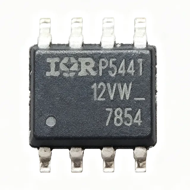

Spezifikationsvergleich
| Parameter | IRF7854TRPBF | IRF7389PBF |
|---|---|---|
| Marke | Infineon | Infineon |
| Kategorie | MOSFETs | MOSFETs |
| Lebenszyklusstatus | Aktiv | Aktiv |
| Lagerstatus | In Stock | In Stock |
| Stückpreis (USD) | $0,48 | $0,61 |
| FET Type | N-Channel | — |
| Drain-Source Voltage (VDS) | 80 V | — |
| Continuous Drain Current (ID) at Ta=25°C | 10 A | — |
| Power Dissipation (PD) at Ta=25°C | 2.5 W | — |
| On-Resistance RDS(on) max at VGS=10V | 13.4 mΩ | — |
| Gate-Source Threshold Voltage VGS(th) max | 4.9 V | — |
| Total Gate Charge Qg | 27 nC | — |
| Gehäuse | SO-8 | SO-8 (SOIC-8) surface mount |
| Montageart | Surface Mount | Surface Mount |
| Technology | HEXFET (planar N-channel) | Generation V HEXFET |
| Betriebstemperaturbereich | -55°C to +150°C (TJ) | [DATA_NEEDED: full operating temperature range] |
| Lead-Free / RoHS | Yes (PBF suffix, lead-free) | — |
| Qualification | JEDEC industrial, Normal level | — |
| Solder Process | Reflow and wave-solderable | — |
| Gate Drive Voltage (recommended) | 10 V | — |
| Configuration | — | N and P-Channel (complementary half-bridge) |
| Drain-to-Source Voltage N-Ch (V_DSS) | — | 30 V |
| Drain-to-Source Voltage P-Ch (V_DSS) | — | -30 V |
| Continuous Drain Current N-Ch (I_D) | — | 7.3 A |
| Continuous Drain Current P-Ch (I_D) | — | -5.3 A |
| On-Resistance N-Ch R_DS(on) max | — | 0.029 ohm at V_GS=10V |
| On-Resistance P-Ch R_DS(on) max | — | 0.058 ohm at V_GS=10V |
| Total Gate Charge N-Ch (Q_g) typical | — | 22 nC |
| Total Gate Charge P-Ch (Q_g) typical | — | 23 nC |
| Power Dissipation (P_D) | — | 2.5 W |
| Pinout | — | Industry-standard complementary SO-8 |
| RoHS-Status | — | Compliant |
| Lead-Free | — | Yes |
| Halogenfrei | — | Yes |
| Avalanche Rated | — | Yes (fully avalanche rated) |