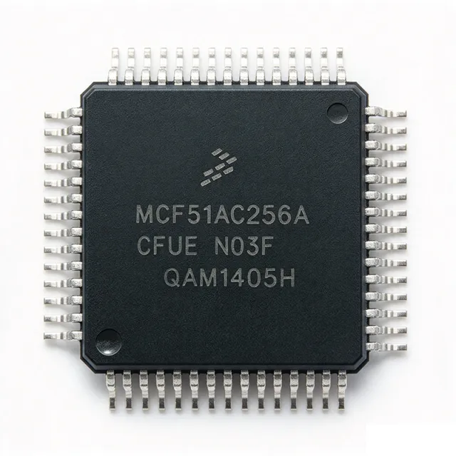
MCF51AC256ACFUE - ColdFire V1 MCU 256KB Flash 50MHz | NXP
Teilenummer: MCF51AC256ACFUE ⚠ Letzte Bestellmöglichkeit| Menge | Stückpreis | Gesamt |
|---|---|---|
| 1 | $14.95 | $14,95 |
| 10 | $13.46 | $134,60 |
| 100 | $11.21 | $1.121,00 |
| 500 | $9.48 | $4.740,00 |
| 1.000 | $8.12 | $8.120,00 |
MCF51AC256ACFUE Übersicht
A microcontroller (MCU) is a single-chip computer that integrates a CPU core, memory (Flash/RAM), and programmable I/O peripherals. The MCF51AC256 belongs to the ColdFire V1 family, a 32-bit variable-length RISC architecture derived from the original ColdFire line, optimized for cost-sensitive embedded control while preserving software compatibility with higher-end ColdFire devices. Within the broader taxonomy: ColdFire V1 -> 32-bit MCU -> microcontroller -> embedded processor -> semiconductor. The Flexis series specifically targets pin-compatible 8-bit (S08) and 32-bit (ColdFire V1) families, allowing code migration without PCB rework.
Key features include 256KB on-chip Flash, 32KB SRAM, integrated CAN 2.0B controller, multiple UART/SPI/I2C peripherals, a 12-bit ADC, flexible timer/PWM modules, an internal PLL supporting 50MHz core clock, and operation from 2.7V to 5.5V. The 64-pin LQFP (14x14 mm) package with 0.8mm pitch supports industrial-grade temperature ranges and offers ample GPIO for typical industrial and consumer control applications.
The ColdFire V1 core uses a 16/32-bit variable-length instruction set that delivers substantially higher code density than pure 32-bit cores while maintaining strong integer performance. Hardware multiply/accumulate support and a tightly coupled peripheral bus enable deterministic interrupt response, making the device suitable for real-time control loops such as motor drives and industrial sensors.
Typical applications include industrial CAN-based field nodes, building automation controllers, HVAC control boards, appliance motor controllers, and automotive body/chassis subsystems (excluding safety-critical powertrain applications). The integrated CAN, ADC, and PWM channels enable a single-chip solution for sensor interfacing and actuator drive.
When designing with this MCU, consider the 50MHz core clock, 3.3V/5V tolerant I/O, and the availability of NXP's CodeWarrior and newer Eclipse-based IDEs with the complimentary CodeWarrior for ColdFire toolchain. Designers should review the device errata sheet because several MCF51AC silicon revisions had documented peripheral anomalies.
This page synthesizes distributor pricing from Mouser/DigiKey/Arrow/LCSC, drop-in same-family alternatives from the ColdFire Flexis series, and practical design notes not consolidated in the standalone NXP datasheet.
Drop-in-Alternativen für MCF51AC256ACFUE – gleiches Gehäuse, Pin-kompatibel. Bauteile mit anderem Gehäuse, die eine PCB-Überarbeitung erfordern, sind ausgeschlossen.
Varianten dieser Serie
Modelle derselben Serie, die drop-in-kompatibel sind mit MCF51AC256ACFUE (gleiche Bauform und Footprint) – abweichend in Package, Series, Core Processor, Core Size, Supply Voltage.
Schnellvergleichstool – Wählen Sie Alternativbauteile für den Direktvergleich:
MCF51AC256BCLKE
✓ Auf Lager
$3.05 / Stück
Datenblatt ansehen →S912XET512BMAGR
✓ Auf Lager
$6.6 / Stück
Datenblatt ansehen →MC9S12A256CFUE
✓ Auf Lager
$47.08 / Stück
Datenblatt ansehen →MC9S12E256CFUE
✓ Auf Lager
$9.75 / Stück
Datenblatt ansehen →MC9S12DB128CFUE
✓ Auf Lager
$14.85 / Stück
Datenblatt ansehen →MCF52252CAF66
✓ Auf Lager
$6.75 / Stück
Datenblatt ansehen →MCF51AC128AVFUE
📋 Referenzalternative (nicht im Katalog)
MCF51AC128CCFUE
📋 Referenzalternative (nicht im Katalog)
MCF51AC256ACFUE Grenzwerte & elektrische Eigenschaften
| Core Architecture | ColdFire V1 (32-bit RISC) |
| Maximum Core Clock | 50 MHz |
| Program Flash | 256 KB |
| SRAM | 32 KB |
| Versorgungsspannung | 2.7 V to 5.5 V |
| Gehäuse | 64-LQFP (14x14 mm) |
| Montageart | Surface Mount |
| Betriebstemperatur | -40C to +85C |
| CAN | 1 x CAN 2.0B controller |
| RoHS-Status | Compliant |
| Lead Free | Yes |
MCF51AC256ACFUE Pin-Konfiguration
| Pin 1 | PTA0 — General-purpose I/O / ADC input / TCLK |
| Pin 2 | PTA1 — General-purpose I/O / ADC input |
| Pin 3 | PTA2 — General-purpose I/O / ADC input |
| Pin 4 | PTA3 — General-purpose I/O / ADC input |
| Pin 5 | PTA4 — General-purpose I/O |
| Pin 6 | PTA5 — General-purpose I/O |
| Pin 7 | PTA6 — General-purpose I/O |
| Pin 8 | PTA7 — General-purpose I/O |
| Pin 9 | PTB0 — General-purpose I/O |
| Pin 10 | PTB1 — General-purpose I/O / SPI |
| Pin 11 | PTB2 — General-purpose I/O / SPI |
| Pin 12 | PTB3 — General-purpose I/O / SPI |
| Pin 13 | PTB4 — General-purpose I/O / SPI |
| Pin 14 | PTB5 — General-purpose I/O / SPI |
| Pin 15 | PTB6 — General-purpose I/O |
| Pin 16 | PTB7 — General-purpose I/O |
| Pin 17 | PTC0 — General-purpose I/O |
| Pin 18 | PTC1 — General-purpose I/O |
| Pin 19 | PTC2 — General-purpose I/O |
| Pin 20 | PTC3 — General-purpose I/O |
| Pin 21 | PTC4 — General-purpose I/O |
| Pin 22 | PTC5 — General-purpose I/O |
| Pin 23 | PTC6 — General-purpose I/O |
| Pin 24 | PTC7 — General-purpose I/O |
| Pin 25 | VDD — Supply voltage (2.7V to 5.5V) |
| Pin 26 | VSS — Ground |
| Pin 27 | PTD0 — General-purpose I/O / CAN RX |
| Pin 28 | PTD1 — General-purpose I/O / CAN TX |
| Pin 29 | PTD2 — General-purpose I/O |
| Pin 30 | PTD3 — General-purpose I/O |
| Pin 31 | PTD4 — General-purpose I/O |
| Pin 32 | PTD5 — General-purpose I/O |
| Pin 33 | PTD6 — General-purpose I/O |
| Pin 34 | PTD7 — General-purpose I/O |
| Pin 35 | PTE0 — General-purpose I/O / SCI TX |
| Pin 36 | PTE1 — General-purpose I/O / SCI RX |
| Pin 37 | PTE2 — General-purpose I/O / SDA |
| Pin 38 | PTE3 — General-purpose I/O / SCL |
| Pin 39 | PTE4 — General-purpose I/O |
| Pin 40 | PTE5 — General-purpose I/O |
| Pin 41 | PTE6 — General-purpose I/O |
| Pin 42 | PTE7 — General-purpose I/O |
| Pin 43 | PTF0 — General-purpose I/O |
| Pin 44 | PTF1 — General-purpose I/O |
| Pin 45 | PTF2 — General-purpose I/O |
| Pin 46 | PTF3 — General-purpose I/O |
| Pin 47 | PTF4 — General-purpose I/O |
| Pin 48 | PTF5 — General-purpose I/O |
| Pin 49 | PTF6 — General-purpose I/O |
| Pin 50 | PTF7 — General-purpose I/O |
| Pin 51 | PTG0 — General-purpose I/O |
| Pin 52 | PTG1 — General-purpose I/O |
| Pin 53 | PTG2 — General-purpose I/O |
| Pin 54 | PTG3 — General-purpose I/O |
| Pin 55 | PTG4 — General-purpose I/O |
| Pin 56 | PTG5 — General-purpose I/O |
| Pin 57 | RESET — Reset input (active low) |
| Pin 58 | IRQ — External interrupt request |
| Pin 59 | EXTAL — External oscillator input |
| Pin 60 | XTAL — External oscillator output |
| Pin 61 | VDD — Supply voltage (2.7V to 5.5V) |
| Pin 62 | VSS — Ground |
| Pin 63 | BKGD — Background debug mode pin |
| Pin 64 | VREFH — ADC reference high voltage |
Typische Anwendungen
MCF51AC256ACFUE ist geeignet für 6 Anwendungs: Industrial CAN Field Nodes, Building Automation Controllers, Appliance Motor Control, Automotive Body and Comfort Modules, Industrial Sensor Hubs, Smart Energy and Metering.
Industrial CAN Field Nodes
The MCF51AC256ACFUE's integrated CAN 2.0B controller plus 50MHz ColdFire V1 throughput make it well-suited for industrial CANopen and DeviceNet slave nodes. The 256KB Flash accommodates CANopen stack libraries and application firmware, while 32KB SRAM holds communication buffers and protocol state. The 64-LQFP industrial footprint at -40C to +85C ensures operation in factory-floor enclosures. Unlike parts without CAN (which need an external SPI-CAN bridge), the integrated controller reduces BOM by approximately $1.50 per node and frees GPIO for sensor interfaces including ADC inputs and PWM outputs for actuator drivers.
Empfohlen
Building Automation Controllers
HVAC and building automation controllers benefit from the MCF51AC256ACFUE's mix of analog and digital peripherals alongside CAN networking. The 50MHz ColdFire V1 core executes control loops for damper actuators, temperature regulation, and lighting while the integrated ADC samples analog sensors. The 64-LQFP package with 0.8mm pitch provides sufficient GPIO for keypad inputs, relay outputs, and LCD interfaces typical in wall-mount thermostats. Wide 2.7V-5.5V supply allows direct connection to 5V legacy building-control rails, simplifying retrofit designs.
Empfohlen
Appliance Motor Control
Washing machines, dishwashers, and refrigerator inverter drives use the MCF51AC256ACFUE for variable-speed motor control. The ColdFire V1 core drives PWM channels for 3-phase inverter timing, reads current sensors via the ADC, and maintains CAN/LIN connectivity for the appliance's master controller. The 50MHz clock provides enough headroom for field-oriented control (FOC) algorithms on BLDC and PMSM motors at switching frequencies up to 20kHz. Compared with simpler 8-bit MCUs, the 32-bit ColdFire V1 single-cycle multiply supports sensorless observer computation in real time.
Empfohlen
Automotive Body and Comfort Modules
Body control modules (BCMs), seat controllers, and HVAC head units use the MCF51AC256ACFUE for non-safety-critical automotive subsystems. The integrated CAN 2.0B controller talks to the vehicle CAN bus, while the ADC captures temperature, humidity, and position sensor inputs. The industrial-grade -40C to +85C rating covers cabin environments. Designers targeting AEC-Q100 should select the automotive-graded Kinetis KE04 family instead; the MCF51AC256ACFUE is suited for non-safety subsystems and aftermarket accessories.
Empfohlen
Industrial Sensor Hubs
Multi-sensor data acquisition hubs use the MCF51AC256ACFUE to aggregate analog and digital sensor data and forward it over CAN or UART to a host controller. The 256KB Flash holds custom calibration tables and signal-processing firmware, while the 32KB SRAM buffers sample arrays before transmission. The 50MHz core executes FIR/IIR filters on incoming ADC streams in real time. Wide supply tolerance (2.7V to 5.5V) supports both 3.3V and 5V sensor networks in process control plants.
Empfohlen
Smart Energy and Metering
Electricity meters, water meters, and substation monitoring equipment use the MCF51AC256ACFUE for energy measurement and data logging. The ColdFire V1 core computes power quality metrics (RMS voltage, current, power factor) from ADC inputs while the CAN interface reports back to a concentrator. The 256KB Flash stores DLMS/COSEM or IEC 62056 protocol stacks, and the 32KB SRAM maintains meter state and tariff tables. Industrial temperature grade ensures operation in outdoor meter enclosures across seasonal extremes.
Empfohlen
Zusammenfassung der empfohlenen Produkte
Technische Referenzdaten für MCF51AC256ACFUE – Vergleich, Designhinweise und Compliance-Informationen.
Auswahlhilfe
Vergleich mit Alternativen
| Parameter | Dieses Produkt | MCF51AC128AVFUE | MCF51AC128CCFUE | MC9S12A256CFUE |
|---|---|---|---|---|
| Brand | NXP Semiconductors | NXP Semiconductors | NXP Semiconductors | NXP Semiconductors |
| Package | 64-LQFP (14x14) | 64-LQFP (14x14) | 64-LQFP (14x14) | 64-LQFP (14x14) |
| Core Architecture | ColdFire V1 (32-bit) | ColdFire V1 (32-bit) | ColdFire V1 (32-bit) | S12 (16-bit) |
| Maximum Clock | 50 MHz | 50 MHz | 50 MHz | 25 MHz bus clock |
| Program Flash | 256 KB | 128 KB (-50%) | 128 KB (-50%) | 256 KB |
| CAN Controller | 1 x CAN 2.0B | 1 x CAN 2.0B | 1 x CAN 2.0B | 1 x CAN 2.0B |
| Operating Temperature | -40C to +85C | -40C to +85C | -40C to +85C | -40C to +85C |
Wichtigste Unterscheidungsmerkmale
- Flexis 8/32-bit pin compatibility (vs. MC9S08AC128 series)
- Integrated CAN 2.0B on-chip (vs. S912XET512BMAGR (S12XE))
- 50 MHz ColdFire V1 throughput (vs. MC9S12A256CFUE (16-bit S12))
Designhinweise
Route the 50MHz ColdFire V1 ECLK and IRQ traces away from analog ADC inputs to minimize digital crosstalk. Place decoupling capacitors (100nF X7R) within 5mm of every VDD/VSS pair. For the 64-LQFP package, provide at least 4 vias beneath the exposed thermal pad to reduce junction-to-ambient thermal resistance, since ColdFire V1 cores can dissipate 250-400 mW at full 50 MHz utilization.
Add a 10uF bulk capacitor plus a 100nF decoupling cap on each VDD pin. The wide 2.7V-5.5V supply range allows direct operation from 5V rails, but an LDO (such as NXP's TLV1117LV) is recommended if analog ADC accuracy targets must be held during CAN bus transients. Brown-out detection should be enabled in the SIM module to prevent code corruption during supply droops below 2.5V.
Review the MCF51AC256 device errata sheet before firmware freeze - several silicon revisions had documented issues with CAN bus-off recovery and ADC accuracy in the first ADC conversion. Configure the ADC in single-ended mode with adequate acquisition time (>= 20 ADC clocks) when sampling high-impedance sources. The BKGD pin should not be left floating during reset; use a weak pull-up to avoid unintended debug-mode entry on noisy power-up.
Estimated thermal performance: at 3.3V supply, 50MHz core clock, and full GPIO toggling, the device consumes approximately 60-80 mA (200-260 mW). With a 64-LQFP theta_JA near 50 C/W on a 4-layer JEDEC test PCB, junction temperature rise above 25C ambient is roughly 13C. Industrial-grade 85C ambient still leaves 60C margin to the 105C junction max.
The ColdFire V1 ECLK output can generate sharp edges; series-terminate clock traces with 33-ohm resistors if the trace exceeds 25mm or has stubs. CAN bus signaling requires a 120-ohm termination resistor at each end of the bus and a common-mode choke on the CANH/CANL lines for EMI-sensitive environments, even though the on-chip CAN controller handles only the protocol layer.
Compliance-Informationen
RoHS compliant per NXP product page. Industrial temperature grade -40C to +85C. Not AEC-Q100 qualified - for automotive safety-critical applications choose a Kinetis KE automotive part.






