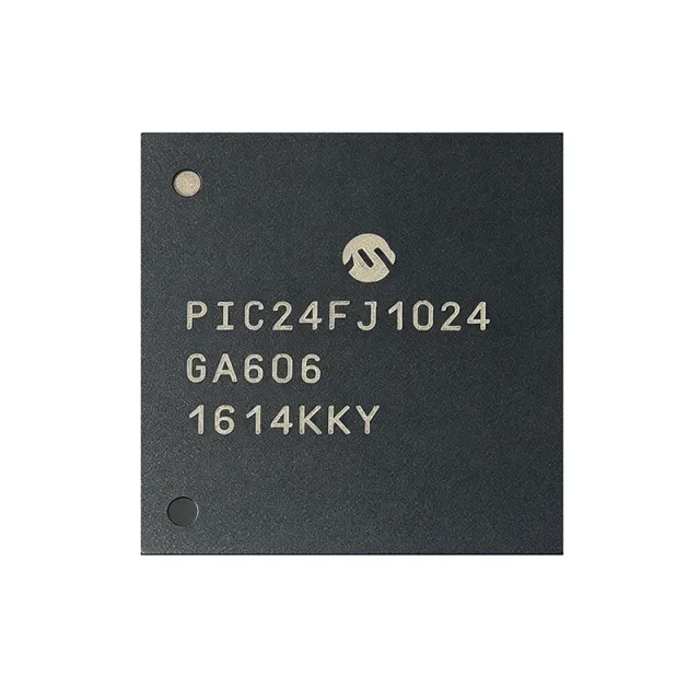
PIC24FJ1024GA606-E/MR - 16-bit 32MHz 1MB Flash MCU | Microchip
Teilenummer: PIC24FJ1024GA606-E/MR ✗ Abgekündigt| Menge | Stückpreis | Gesamt |
|---|---|---|
| 1 | $11.5 | $11,50 |
| 10 | $10.35 | $103,50 |
| 100 | $9.2 | $920,00 |
| 500 | $8.28 | $4.140,00 |
| 1.000 | $7.36 | $7.360,00 |
PIC24FJ1024GA606-E/MR Übersicht
A PIC microcontroller (MCU) is a compact, low-cost, programmable processor that integrates a CPU, non-volatile program storage, working RAM, and configurable peripherals onto a single silicon die. The PIC24F family from Microchip extends the 8-bit PIC16/PIC18 architecture into a 16-bit modified-Harvard core, enabling more computational throughput (measured in MIPS) and richer peripherals while preserving the deterministic interrupt model and low-power sleep modes that made the platform popular. PIC MCUs are widely used in industrial sensing, motor control, and consumer devices where ease of development, long product lifecycles, and stable supply matter more than peak raw performance.
Key features include dual-bank Flash with live update capability, on-chip ECC for higher reliability, deep sleep currents in the microamp range, and an integrated USB 2.0 full-speed OTG controller. The 16 analog channels are suitable for multi-sensor acquisition boards, while the DMA-driven peripheral set reduces CPU load in data-pump applications. The wide 3.0 V-3.6 V supply range simplifies battery-powered designs and 3.3 V point-of-load architectures.
Architecturally, the PIC24FJ1024GA606 uses a 16-bit modified-Harvard core with hardware multiply/divide, a multi-vector interrupt controller, and Microchip's PMM power management unit. The dual-partition Flash supports live update (running one bank while erasing/writing the other), enabling firmware-in-the-field upgrades without service interruption. Peripherals are routed through Microchip's PPS (Peripheral Pin Select) system, allowing flexible assignment of digital functions to most I/O pins.
Typical applications include industrial control and HMI panels, low-power IoT sensor nodes, automotive body and accessory ECUs, USB peripherals and embedded host devices, and portable medical instrumentation. For IoT designs, the combination of deep-sleep modes and live-update Flash is especially valuable - nodes can sleep for years on a single battery cell yet receive secure OTA firmware updates in the field. For industrial HMI panels, the 16 analog inputs and graphics-ready PWM timers are well-suited to touch + TFT implementations.
When designing with this MCU, pay attention to the PLL configuration sequence and the Vbat/Vddcore/Vddio decoupling layout, since high-speed ADC sampling noise can couple from digital rails. The dual-partition Flash and Live Update flow should be exercised during prototyping; failed live updates can brick the device if the bootloader is not robust.
This page synthesizes distributor pricing, drop-in same-package alternatives, and practical design notes not collected in a single place in the manufacturer datasheet.
Drop-in-Alternativen für PIC24FJ1024GA606-E/MR – gleiches Gehäuse, Pin-kompatibel. Bauteile mit anderem Gehäuse, die eine PCB-Überarbeitung erfordern, sind ausgeschlossen.
Varianten dieser Serie
Modelle derselben Serie, die drop-in-kompatibel sind mit PIC24FJ1024GA606-E/MR (gleiche Bauform und Footprint) – abweichend in Package, ADC, MSL Level, Core, Operating Temperature.
Schnellvergleichstool – Wählen Sie Alternativbauteile für den Direktvergleich:
PIC24FJ1024GA606-I/MR
✓ Auf Lager
$4.85 / Stück
Datenblatt ansehen →PIC24FJ1024GA606-E/PT
✓ Auf Lager
$5.5 / Stück
Datenblatt ansehen →PIC24FJ1024GA606T-E/MR
📋 Referenzalternative (nicht im Katalog)
PIC24FJ1024GB606-I/MR
📋 Referenzalternative (nicht im Katalog)
PIC24FJ1024GA610-I/MR
📋 Referenzalternative (nicht im Katalog)
PIC24FJ1024GA606-E/MR Grenzwerte & elektrische Eigenschaften
| Core | PIC24 (16-bit modified Harvard) |
| CPU Architecture | 16-bit RISC, hardware multiply/divide |
| Maximum CPU Clock | 32 MHz (16 MIPS) |
| Program Memory (Flash) | 1 MB (341.5K x 24) |
| Data RAM | 32 KB |
| Flash Features | Dual Partition with Live Update and ECC |
| Supply Voltage (Vdd) | 3.0 V to 3.6 V |
| Betriebstemperatur | -40C to +125C (E grade = extended) |
| UART | 6 |
| SPI | 3 |
| I2C | 3 |
| IrDA | 2 |
| PWM Channels | 6 |
| 16-bit Timers | 5 |
| Analog Comparators | 3 |
| DMA Channels | 8 |
| Analog Input Channels | 16 |
| ADC Resolution | 10/12-bit |
| USB | USB 2.0 Full-Speed OTG (on select family variants) |
| Gehäuse | 64-QFN (MR) 9 mm x 9 mm with exposed pad |
| Montageart | Surface Mount |
| AEC-Q100 | Qualified (automotive grade) |
| RoHS-Status | Compliant |
PIC24FJ1024GA606-E/MR Pin-Konfiguration
| Pin 1 | RA0 — Digital I/O / analog input AN0 / PPS function |
| Pin 2 | RA1 — Digital I/O / analog input AN1 / PPS function |
| Pin 3 | RA2 — Digital I/O / analog input AN2 / PPS function |
| Pin 4 | RA3 — Digital I/O / analog input AN3 / PPS function |
| Pin 5 | RA4 — Digital I/O / analog input AN4 / PPS function |
| Pin 6 | RA5 — Digital I/O / analog input AN5 / PPS function |
| Pin 7 | RA6 — Digital I/O / analog input AN6 / PPS function |
| Pin 8 | RA7 — Digital I/O / analog input AN7 / PPS function |
| Pin 9 | VDD — Digital supply voltage (3.0 V to 3.6 V) |
| Pin 10 | VSS — Digital ground |
| Pin 11 | RB0 — Digital I/O / PGED1 / programming data |
| Pin 12 | RB1 — Digital I/O / PGEC1 / programming clock |
| Pin 13 | RB2 — Digital I/O / analog input AN8 / PPS function |
| Pin 14 | RB3 — Digital I/O / analog input AN9 / PPS function |
| Pin 15 | RB4 — Digital I/O / analog input AN10 / PPS function |
| Pin 16 | RB5 — Digital I/O / analog input AN11 / PPS function |
| Pin 17 | RB6 — Digital I/O / analog input AN12 / PPS function |
| Pin 18 | RB7 — Digital I/O / analog input AN13 / PPS function |
| Pin 19 | RB8 — Digital I/O / analog input AN14 / PPS function |
| Pin 20 | RB9 — Digital I/O / analog input AN15 / PPS function |
| Pin 21 | RC0 — Digital I/O / PPS function |
| Pin 22 | RC1 — Digital I/O / PPS function |
| Pin 23 | RC2 — Digital I/O / PPS function |
| Pin 24 | RC3 — Digital I/O / PPS function |
| Pin 25 | RC4 — Digital I/O / PPS function |
| Pin 26 | RC5 — Digital I/O / PPS function |
| Pin 27 | RC6 — Digital I/O / PPS function |
| Pin 28 | RC7 — Digital I/O / PPS function |
| Pin 29 | RC8 — Digital I/O / PPS function |
| Pin 30 | RC9 — Digital I/O / PPS function |
| Pin 31 | VSS — Digital ground |
| Pin 32 | VDD — Digital supply voltage (3.0 V to 3.6 V) |
| Pin 33 | RD0 — Digital I/O / PPS function |
| Pin 34 | RD1 — Digital I/O / PPS function |
| Pin 35 | RD2 — Digital I/O / PPS function |
| Pin 36 | RD3 — Digital I/O / PPS function |
| Pin 37 | RD4 — Digital I/O / PPS function |
| Pin 38 | RD5 — Digital I/O / PPS function |
| Pin 39 | RD6 — Digital I/O / PPS function |
| Pin 40 | RD7 — Digital I/O / PPS function |
| Pin 41 | RD8 — Digital I/O / PPS function |
| Pin 42 | RD9 — Digital I/O / PPS function |
| Pin 43 | RD10 — Digital I/O / PPS function |
| Pin 44 | RD11 — Digital I/O / PPS function |
| Pin 45 | RD12 — Digital I/O / PPS function |
| Pin 46 | RD13 — Digital I/O / PPS function |
| Pin 47 | RD14 — Digital I/O / PPS function |
| Pin 48 | RD15 — Digital I/O / PPS function |
| Pin 49 | RE0 — Digital I/O / PPS function |
| Pin 50 | RE1 — Digital I/O / PPS function |
| Pin 51 | RE2 — Digital I/O / PPS function |
| Pin 52 | RE3 — Digital I/O / PPS function |
| Pin 53 | RE4 — Digital I/O / PPS function |
| Pin 54 | RE5 — Digital I/O / PPS function |
| Pin 55 | RE6 — Digital I/O / PPS function |
| Pin 56 | RE7 — Digital I/O / PPS function |
| Pin 57 | VSS — Digital ground |
| Pin 58 | VDD — Digital supply voltage (3.0 V to 3.6 V) |
| Pin 59 | RF0 — Digital I/O / PPS function |
| Pin 60 | RF1 — Digital I/O / PPS function |
| Pin 61 | RF2 — Digital I/O / PPS function |
| Pin 62 | RF3 — Digital I/O / PPS function |
| Pin 63 | RF4 — Digital I/O / PPS function |
| Pin 64 | RF5 — Digital I/O / PPS function |
Typische Anwendungen
PIC24FJ1024GA606-E/MR ist geeignet für 6 Anwendungs: Industrial Control & HMI Panels, Low-Power IoT Sensor Nodes, Automotive Body & Accessory ECUs, USB Peripherals & Embedded Host, Portable Medical Instrumentation, Motor Control & Drive Boards.
Industrial Control & HMI Panels
The PIC24FJ1024GA606-E/MR fits industrial HMI panels because its 1 MB Flash holds TFT graphics frames and full Modbus stacks, while 32 KB RAM supports localized UI state. The 16 analog channels digitize potentiometer, RTD, or 4-20 mA sensor inputs directly through the 10/12-bit ADC, and the 6 PWM channels drive LED backlight dimming or small BLDC fans without an external controller. Six UARTs handle RS-232/RS-485 fieldbus bridges, while dual-partition Flash with Live Update lets the panel be reflashed in the field without service interruption - critical for factory floor downtime reduction. The 64-QFN MR package provides a compact footprint and the exposed pad enables reliable thermal dissipation inside a sealed enclosure.
Empfohlen
Low-Power IoT Sensor Nodes
The PIC24FJ1024GA606-E/MR is well suited to battery-powered IoT sensor nodes because the eXtreme Low Power PIC24F core offers deep-sleep currents in the microamp range, while the 1 MB dual-partition Flash and Live Update enable OTA firmware upgrades that cannot brick deployed units. The 3 UARTs can drive a LoRa or NB-IoT module, while the 3 I2C and 3 SPI ports connect to multiple environmental sensors simultaneously. DMA channels offload sensor acquisition so the CPU spends almost all its time in sleep, extending coin-cell life into multi-year territory. The 32 KB RAM buffers a full Modbus or MQTT payload between transmit windows.
Empfohlen
Automotive Body & Accessory ECUs
The PIC24FJ1024GA606-E/MR is AEC-Q100 qualified and operates over -40C to +125C, making it appropriate for body controllers, lighting modules, accessory ECUs, and HVAC panels. The 6 PWM channels drive LED matrix lighting or motor speed control; 6 UARTs interface to CAN-LIN gateways and other ECUs over the vehicle network; the 16 analog channels read potentiometers, thermistors, and battery voltage under cranking transients. Dual-partition Flash with Live Update satisfies OEM service-tool reprogramming requirements without ECU downtime, while ECC-protected Flash improves reliability in noisy under-hood electrical environments. The 64-QFN MR footprint is well established across Microchip automotive designs.
Empfohlen
USB Peripherals & Embedded Host
For designs needing USB connectivity, consider the sibling PIC24FJ1024GB606 family in the same 64-QFN MR footprint, which adds a USB 2.0 Full-Speed OTG controller for both device and embedded host operation. The GA606 itself serves in peripheral designs where USB is not required but the same 1 MB Flash, 32 KB RAM, and rich peripheral set are still desired. The DMA controller handles sustained USB traffic without CPU intervention, leaving the PIC24F core free for protocol stacks or device class logic. This combination is widely deployed in USB HID, CDC, and mass-storage devices that also need multi-sensor I/O.
Empfohlen
Portable Medical Instrumentation
The PIC24FJ1024GA606-E/MR supports portable medical devices such as glucose meters, pulse oximeters, and handheld patient monitors thanks to its 16 analog channels, 10/12-bit ADC resolution, and eXtreme Low Power deep-sleep modes that extend battery life between uses. The 32 KB RAM and 1 MB Flash host a real-time operating system, BLE or NFC pairing stacks, and clinical UI graphics; the 6 UARTs bridge to wireless modules for telemetry, while the 3 I2C ports handle sensor ASICs. The AEC-Q100 qualification (-40C to +125C) gives extra margin against the temperature swings of clinical environments, and dual-partition Flash supports FDA-style validated firmware updates.
Empfohlen
Motor Control & Drive Boards
The PIC24FJ1024GA606-E/MR drives small BLDC, stepper, and brushed-DC motors in low-voltage applications such as appliance pumps, fans, and small robotic joints. Its 6 PWM channels with complementary outputs and programmable dead-time handle 3-phase motor commutation; 5 timers provide input capture for encoder feedback; and the DMA controller streams encoder and current-sense samples without CPU overhead. The 16 analog inputs support multi-shunt current sensing and back-EMF measurement. Dual-partition Flash lets drive firmware be tuned in the field, while ECC improves reliability against the electrical noise of switching power stages.
Empfohlen
Zusammenfassung der empfohlenen Produkte
Technische Referenzdaten für PIC24FJ1024GA606-E/MR – Vergleich, Designhinweise und Compliance-Informationen.
Auswahlhilfe
Vergleich mit Alternativen
| Parameter | Dieses Produkt | PIC24FJ1024GA606-I/MR | PIC24FJ1024GA606T-E/MR | PIC24FJ1024GB606-I/MR | PIC24FJ1024GA606-E/PT | PIC24FJ1024GA610-I/MR |
|---|---|---|---|---|---|---|
| Package | 64-QFN (MR) 9x9 mm | 64-QFN (MR) 9x9 mm - same | 64-QFN (MR) 9x9 mm - same | 64-QFN (MR) 9x9 mm - same | 64-TQFP (PT) - different | 64-QFN (MR) 9x9 mm - same |
| Brand | Microchip Technology | Microchip Technology | Microchip Technology | Microchip Technology | Microchip Technology | Microchip Technology |
| Core | PIC24F 16-bit @ 32 MHz | PIC24F 16-bit @ 32 MHz | PIC24F 16-bit @ 32 MHz | PIC24F 16-bit @ 32 MHz | PIC24F 16-bit @ 32 MHz | PIC24F 16-bit @ 32 MHz |
| Program Flash | 1 MB (dual partition, ECC) | 1 MB (dual partition, ECC) | 1 MB (dual partition, ECC) | 1 MB (dual partition, ECC) | 1 MB (dual partition, ECC) | 1 MB (dual partition, ECC) |
| RAM | 32 KB | 32 KB | 32 KB | 32 KB | 32 KB | 32 KB |
| Temperature Grade | -40C to +125C (E grade, AEC-Q100) | -40C to +85C (I grade, industrial) | -40C to +125C (E grade, AEC-Q100) | -40C to +85C (I grade, industrial) | -40C to +125C (E grade, AEC-Q100) | -40C to +85C (I grade, industrial) |
| USB 2.0 OTG | No | No | No | Yes | No | No |
| UART / SPI / I2C | 6 / 3 / 3 | 6 / 3 / 3 | 6 / 3 / 3 | 6 / 3 / 3 | 6 / 3 / 3 | 6 / 3 / 3 |
| Approx Unit Price (USD, qty 1, as of 2026-09-29) | 11.50 | 9.50 | 11.50 | 11.20 | 11.40 | 10.00 |
Wichtigste Unterscheidungsmerkmale
- Dual-partition Flash with Live Update and ECC (vs. PIC24FJ1024GA606-I/MR (industrial grade))
- AEC-Q100 automotive qualification (-40C to +125C) (vs. PIC24FJ1024GA606-I/MR)
- 64-QFN (MR) 9x9 mm compact footprint (vs. PIC24FJ1024GA606-E/PT (64-TQFP))
Designhinweise
Decouple every VDD/VSS pair of the PIC24FJ1024GA606-E/MR with a 100 nF ceramic cap placed within 5 mm of each pin pair, and add a single 4.7 uF bulk capacitor near the package exposed pad. According to the PIC24FJ1024GA610/GB610 family datasheet DS30010074F, the ADC accuracy degrades noticeably when VDD ripple exceeds 50 mV during conversion. Use a star-ground topology that ties the MCU ground pin directly to the exposed pad copper pour.
The 64-QFN MR package relies on the exposed thermal pad for heat removal. Stitch a continuous ground copper pour directly under the pad with at least 16 thermal vias (0.3 mm drill, 0.6 mm pitch) to an internal ground plane. Without adequate PCB thermal dissipation, junction temperature can exceed the +125C automotive limit at sustained 32 MHz operation with all peripherals active. Estimated: at 32 MHz full-load, internal dissipation is approximately 60-80 mW; with proper PCB layout theta_JA stays below 30 C/W.
Route the ICSP pair PGEC1/PGED1 (RB1/RB0) directly to an in-circuit programming header without series resistors, and place the header at the board edge for easy probe access during manufacturing. Keep the trace length under 50 mm and avoid stubs - long ICSP traces can cause programming failures and ICE debug errors. According to the family datasheet, any PGECx/PGEDx pair can be used for ICSP but they must be used as a matched pair.
When using Live Update on the dual-partition Flash, ensure the bootloader is in a protected boot segment and implements a fail-safe rollback to the last known-good image; a failed live update without rollback can brick the device in the field. Always verify the Vbat domain is correctly bonded if RTC retention is required - leaving Vbat floating can cause unpredictable brown-out resets. The PMM must be configured per the family datasheet DS30010074F before any PLL or peripheral activation.
Separate the analog and digital ground domains on the PCB; join them at a single point under the MCU exposed pad to avoid ground-loop noise coupling into the ADC. Place the analog input traces on the opposite side of any high-speed digital signals (SPI, PWM outputs), and surround analog inputs with a guard trace tied to analog ground. Use PPS to remap noisy digital peripherals away from analog-capable pins when possible. PPS assignments should be locked early in firmware to avoid peripheral conflicts at boot.
Compliance-Informationen
AEC-Q100 qualified per Hotenda listing. RoHS and REACH compliant per Microchip product page. Halogen-free status not explicitly stated in verified data.







