RF y Wireless
Subcategorías
Productos (682)

E180-2G4Z20SX-TB - EFR32MG21 ZigBee 3.0 Test Kit | EBYTE
The Chengdu Ebyte E180-2G4Z20SX-TB is a development test board based on the E180-2G4Z20SX wireless module, integrating the Silicon Labs EFR32MG21 ZigBee 3.0 SoC with an integrated power amplifier in a compact 28.5 x 24.6 mm USB-stick form factor pre-soldered to the carrier PCB. A ZigBee module is a pre-certified, surface-mount radio module that integrates an RF transceiver, microcontroller, antenna interface, and matching networks into a single shielded package. ZigBee modules belong to the broader hierarchy of wireless connectivity modules -> short-range IoT radios -> 2.4 GHz ISM-band transceivers -> IEEE 802.15.4-based mesh networking devices, designed to reduce RF design complexity for OEMs building mesh-enabled smart products. Key features of the E180-2G4Z20SX-TB test kit include: the host module operates in the 2.4 GHz ISM band with maximum transmit power of 20 dBm, supports ZigBee 3.0 self-organizing mesh networking, and provides USB power and serial port access via a 2.0 mm pitch pin header. The carrier PCB is pre-soldered to the E180-2G4Z20SX module so developers can plug the kit directly into a breadboard or USB host. Product weight is 3.5 g +/- 0.1 g. The E180-2G4Z20SX-TB is purpose-built for engineers evaluating the E180-2G4Z20SX module: it exposes the module's UART, GPIO, and power pins through standard 2.54 mm headers, removes RF layout risk during firmware bring-up, and ships with reference firmware for rapid ZigBee 3.0 stack validation. The internal PA delivers the 20 dBm TX power needed for long-range mesh nodes. Typical applications include ZigBee 3.0 smart-home device prototyping, industrial sensor mesh networking, smart metering pilots, building automation gateways, and wireless HVAC/lighting control development. The test kit is also used as a reference design for designers integrating the bare E180-2G4Z20SX module into their own carrier PCB. When designing with this test kit, note that the kit is a development-only assembly - it is not intended for deployment in the final product. For production designs, use the host E180-2G4Z20SX module directly on a custom carrier PCB and obtain modular transmitter / certification requirements before shipping. This page synthesizes distributor pricing, drop-in alternatives, and practical design notes not found in the manufacturer datasheet, giving engineers a single source for E180-2G4Z20SX-TB selection, sourcing, and integration guidance.
E180-Z6907A - 2.4GHz ZigBee 3.0 SoC Module, 7dBm, TLSR8269
Chengdu Ebyte E180-Z6907A is a surface-mount 2.4 GHz ZigBee 3.0 wireless SoC module built around the Telink TLSR8269 chip, delivering 7 dBm transmit power with -40C to +85C industrial operating range in an 11.5 x 22 mm SMD package with on-board PCB antenna. A ZigBee module is a pre-certified, RF-tested sub-system that integrates the radio transceiver, microcontroller, antenna, and matching network into a single drop-in component, allowing designers to add mesh networking capability without performing RF layout, impedance matching, or radio regulatory compliance from scratch. Within the broader taxonomy, the E180-Z6907A sits inside RF & Wireless > RF Modules, and the underlying TLSR8269 belongs to the IEEE 802.15.4 / ZigBee family of low-power, low-data-rate mesh protocols used for short-range IoT connectivity. This background matters because antenna integration, regional RF certification (FCC, CE, SRRC), and firmware stack licensing are typically the largest engineering risks in any wireless product, and integrating a certified module eliminates most of them. Key specifications include 7 dBm typical transmit power, a stated link range of approximately 130 m line-of-sight at low data rate, and a supply voltage of 3.3 V with peak TX current near 65 mA and RX/TX-idle current near 40 mA. The module exposes GPIO for host interfacing, supports on-chip battery telemetry for battery-powered devices, and includes an RF diagnostic function for production testing and link debugging. The integrated PCB antenna eliminates the need for an external antenna trace. Architecturally, the TLSR8269 combines a 32-bit MCU core with an IEEE 802.15.4 / Bluetooth Low Energy / RF 6E capable 2.4 GHz radio, allowing the same module to participate in ZigBee 3.0 mesh networks or proprietary point-to-point links depending on firmware. Ebyte ships the module with a ZigBee 3.0 stack pre-loaded; engineers who need BLE or proprietary protocols can reflash using Telink's TLSR8269 SDK and the Ebyte hardware programming pins. Typical applications include smart-home lighting, door/window sensors, occupancy and environmental sensors, smart plugs, and ZigBee coordinators or routers for mesh networks. The small SMD footprint suits space-constrained designs such as in-wall switches and battery-powered sensor nodes. Design consideration: this module is SMD reflow-only (220C peak per JEDEC J-STD-020), and the antenna keep-out zone on the host board must remain clear of copper, traces, and grounded metal within roughly 5 mm of the PCB antenna edge to preserve radiated performance. This page synthesizes distributor pricing, drop-in alternatives, and practical design notes not found in the manufacturer datasheet.
E180-ZG120A - 2.4GHz ZigBee 3.0 Module, 20dBm, EFR32MG1B | EBYTE
The EBYTE E180-ZG120A is a compact, surface-mount 2.4 GHz ZigBee 3.0 wireless module built on the EFR32MG1B "Mighty Gecko" SoC from Silicon Labs, housed in a 17.5 x 28.7 mm SMD package and certified to CE/FCC/RoHS standards. It delivers +20 dBm (100 mW) transmit output power with an integrated high-efficiency PA and LNA chain, enabling a line-of-sight range of approximately 1 km and high sensitivity reception in noisy RF environments. A ZigBee module is a pre-certified, application-ready radio subsystem that integrates the RF transceiver, microcontroller, antenna matching network, and regulatory shielding into a single reflow-compatible component. It belongs to the product taxonomy: ZigBee module -> 802.15.4 wireless module -> short-range IoT radio module -> RF & Wireless module -> electronic component. By embedding an ARM Cortex-M4 core with up to 256 kB flash and 32 kB RAM, the E180-ZG120A removes the design complexity of impedance-controlled RF layout from the integrator's responsibility, dramatically shortening time-to-market for IEEE 802.15.4 products. Key features include full ZigBee 3.0 protocol stack support, GPIO exposure through castellated edge pads, an integrated PCB antenna with optional external antenna variants, low standby current for battery-powered nodes, and an operating temperature range suited to industrial IoT deployments. Compared with bare-chip CC2530 designs, the PA+LNA chain on the EFR32MG1B platform delivers substantially better link margin in industrial environments. Technically, the module exposes the Silicon Labs EFR32MG1B232F256GM48 die with hardware-accelerated AES-128/256, true random number generation, and rich peripheral set including ADC, timers, USART, and I2C. Developers can program the module directly via Silicon Labs' Simplicity Studio toolchain and EmberZNet (ZigBee 3.0) or OpenThread/Zigbee R22 SDK, with reference designs for coordinator, router, and end-device roles available from the manufacturer. Typical applications include ZigBee 3.0 smart home hubs, wireless lighting control, building automation sensor meshes, industrial telemetry, and battery-powered end devices such as window/door sensors and HVAC thermostats. The integrated antenna footprint and pre-loaded EmberZNet image make it ideal for low-volume OEM products that need a fast regulatory path. When designing with this module, follow the manufacturer's PCB keep-out region around the integrated antenna, observe reflow profile of 245 C peak, and verify that the host product's enclosure material does not deshalve more than 3 dB of radiated power. Stack-up and supply decoupling should follow Silicon Labs' AN1018 reference for best RF performance. This page consolidates distributor pricing, pin-compatible module swaps, and reference-design workflows beyond the manufacturer datasheet to support fast BOM decisions for ZigBee 3.0 product teams.
E180-ZG120B - 2.4GHz ZigBee 3.0 SMD Module | EBYTE
The EBYTE E180-ZG120B is a small, low-power, high-reliability 2.4 GHz ZigBee SMD wireless module based on the Silicon Labs EFR32MG1B SoC, integrating a high-performance 32-bit ARM Cortex-M4 core with an integrated power amplifier delivering up to 19 dBm (20 dBm typical chip-side) transmit output. The module measures 18 x 11.5 mm in surface-mount form factor, runs on a 3.3 V supply, and includes an IPEX/U.FL antenna connector for flexible RF chain design. A ZigBee module is a pre-certified surface-mount radio block that combines an RF transceiver, microcontroller, crystal oscillator, and matching network into a single shield-ready component. Within the broader wireless taxonomy, ZigBee (IEEE 802.15.4) sits alongside BLE, Thread, and proprietary sub-GHz protocols as a low-power mesh networking standard for IoT. The E180-ZG120B specifically supports ZigBee 3.0, enabling interoperability with the ZigBee Home Automation, Light Link, and Green Power profiles for unified mesh device ecosystems. Key features include 19 dBm (135 mA peak) maximum RF output, 10 mA average receive current, SMD package with castellated edge contacts, UART host interface, and an operating temperature range of -40 C to +85 C. The module exposes GPIO pins and supports AT command-mode as well as transparent serial-port operation, simplifying integration into legacy and new MCU designs. The EFR32MG1B SoC core delivers Cortex-M4 processing with built-in hardware crypto, hardware AES, and integrated balun, eliminating the need for external RF components. The internal PA bypass network and SAW filter on the module PCB provide 1.3 km line-of-sight range per the manufacturer's benchmark, while sleep current in low-power modes enables multi-year battery operation. Pre-loaded ZigBee 3.0 stack reduces firmware development time. Typical applications include smart home lighting and switch control, ZigBee 3.0 coordinator and router nodes, industrial sensor telemetry, wireless meter reading, and remote control scenarios where mesh networking and AES-128 security are required. The module's compact SMD footprint suits dense PCB designs and reflow-compatible assembly. For best performance, place the module at the PCB edge away from metal enclosures, route the IPEX antenna path clear of ground pours, and provide a stable 3.3 V LDO with at least 200 mA headroom to handle the 135 mA transmit peak. The UART baud rate, GPIO mapping, and AT command set are configured through the host MCU. This page synthesizes distributor pricing, drop-in alternatives, and practical design notes that complement the official E180-ZG120A/B user manual v1.0 from Chengdu Ebyte Electronic Technology.
E22-400M22S - SX1268 LoRa 22dBm 7km 410-493MHz Module | EBYTE
The EBYTE E22-400M22S is an industrial-grade, surface-mount LoRa RF transceiver module built around the Semtech SX1268 chip, delivering up to 22.3 dBm (170 mW) of transmit output power and a stated line-of-sight range of 7 km over the 410-493 MHz ISM band, packaged in a compact 20 x 14 mm SMD-22 stamp-hole footprint with both on-board chip antenna and U.FL (IPEX) external antenna connector options. What is a LoRa transceiver module? A LoRa (Long Range) transceiver module is a complete sub-system that combines a Semtech LoRa-modulation radio IC, an RF front-end (PA, LNA, filtering, antenna switch), a TCXO or crystal reference, and an SPI host interface on a single PCB. It belongs to the broader family of wireless modules -> sub-GHz transceivers -> RF modules -> RF & wireless modules. Designers use LoRa modules instead of bare LoRa ICs to skip RF layout certification and pass radio regulations in target regions more easily. Key features of the E22-400M22S include a -147 dBm receive sensitivity that enables long-range links, a wide 1.8 V to 3.7 V supply window that is friendly to Li-ion and 2xAA battery rails, programmable output power from a few mW up to 22.3 dBm, support for both LoRa spread-spectrum modulation and traditional GFSK, and a 32 MHz high-precision TCXO that improves frequency stability under temperature swing. The SX1268 inside also offers an integrated DC-DC converter option for improved transmit efficiency. The module architecture is built on Semtech's SX1268, the 410-810 MHz variant of the SX126x family, paired with an external power amplifier path to reach the 22 dBm level, an SAW band filter for out-of-band rejection, and an SPI bus for register access from the host MCU. Compatibility with the older SX1276/SX1277/SX1278 commands simplifies migration for existing LoRa designs, while the SX1268 offers lower receive current and higher bit-rate flexibility. Typical applications include remote metering and automatic meter reading (AMR), agricultural soil and irrigation sensors, industrial wireless telemetry over 433/470 MHz license-free bands, smart home and building automation backhaul, asset tracking in outdoor yards, and long-range drone or robotics telemetry links where a 7 km class range is required. A key design consideration is antenna selection: at 433/470 MHz a correctly tuned external antenna on the U.FL connector delivers far better range than the on-board chip antenna, and a 50 ohm controlled-impedance feed must be maintained. Designers should also budget for the 100 mA peak supply current during +22 dBm transmit bursts and decouple the supply rail close to the module pins. This page synthesizes distributor pricing, SX1268 versus SX1278 migration notes, drop-in same-footprint alternatives, and practical antenna and power-rail design guidance not found in the EBYTE datasheet alone, giving engineers a single decision-grade reference for selecting and implementing the E22-400M22S.
E22-400MM22S - SX1268 LoRa 433/470MHz Module | Ebyte
The Chengdu Ebyte E22-400MM22S is an ultra-small SMD LoRa wireless transceiver module operating over a continuous 410-493 MHz frequency range (covering the 433 MHz and 470 MHz ISM bands), with 22.3 dBm maximum transmit power and -147 dBm receive sensitivity in a 10 x 10 mm castellated (stamp-hole) SMD package with IPEX antenna interface option. A LoRa module is a sub-GHz radio transceiver subsystem that implements Semtech's LoRa spread-spectrum (chirp spread spectrum) and traditional GFSK modulation to deliver long-range, low-power wireless links. Within the system hierarchy it sits above the bare RF chip (here the Semtech SX1268) and below full application nodes, providing the RF front end, matching network, and host interface that an MCU controls over SPI. Key features include a very low receive current of 6.5 mA (with DC-DC power configuration), wide 1.8 V to 3.7 V supply range, transmit current of 100 mA, and a communication range of up to 7 km in open field. The SX1268 core supports multiple modulation schemes, enabling both long-range LoRa links and higher-throughput GFSK links on the same hardware. The SX1268 generation adds improved link budget and configurable power-amplifier and LDO/DC-DC supply modes; selecting the high-efficiency buck converter mode substantially lowers receive current for battery-powered nodes. Sensitivity of -147 dBm at low data rates allows deep penetration and multi-kilometer range, making the module well suited to dense deployments with infrequent small-payload transmissions. Typical applications include smart agriculture sensor nodes, industrial telemetry and metering, smart-city infrastructure, and asset tracking in the 433/470 MHz regional ISM bands. Design consideration: at 22.3 dBm output the module requires a good ground plane and an efficient antenna (IPEX whip or matched PCB antenna); always verify duty-cycle and EIRP limits for your regional 433/470 MHz regulations before deployment. This page synthesizes distributor pricing from LCSC, JLCPCB, and Chipmall, drop-in alternative analysis, and practical design notes not found in the manufacturer datasheet.
EC21AFA-512-STD - LTE Cat 1 M2M Module | Quectel
The Quectel EC21AFA-512-STD is an LTE Cat 1 cellular module for M2M and IoT applications, delivering maximum downlink data rates up to 10 Mbps with LTE and WCDMA (3G) fallback support, in a surface-mount card-edge (LCC) package without an integrated antenna. The AFA suffix designates the North America variant, targeting carriers across the US and Canada. An LTE Cat 1 module is a category of LTE UE device class defined for low-cost, low-power machine-type communication. Within the wireless connectivity hierarchy (cellular module -> RF transceiver module -> wireless communication device), Cat 1 sits above Cat M1/NB-IoT in throughput but below Cat 4 and higher, making it the traditional choice for 2G/3G sunset migrations where a full-speed LTE fallback to WCDMA is required without the cost of higher LTE categories. Key features include cost-effective LTE Cat 1 connectivity with downlink speeds up to 10 Mbps, integrated WCDMA fallback for coverage resilience, and on-module memory comprising 4 Gbit ROM and 2 Gbit RAM, which supports embedded applications and firmware headroom. Because the antenna is external, designers retain full flexibility in antenna selection and placement for optimal RF performance in enclosures. The EC21 series architecture integrates the cellular modem, baseband, RF transceiver, and memory into a single LCC-style castellated package designed for reflow soldering onto the host PCB, a pattern common across Quectel's EC2x family, which simplifies layout reuse across family members. Typical applications include telematics and fleet tracking units, smart metering and utility gateways, industrial routers and DTUs, security and alarm panels, and POS terminals - all scenarios where reliable mid-rate cellular data and long product lifecycles matter more than peak throughput. A key design consideration is thermal and RF layout: the module must be placed with adequate ground plane and the external antenna matched per the carrier band plan for the North America variant; power supply sequencing and a stable 3.3-4.2 V rail with sufficient burst current are critical for LTE transmit bursts. This page synthesizes distributor availability from DigiKey, Mouser, Arrow, Avnet and Octopart, same-family drop-in alternatives, and practical design notes not found in the manufacturer datasheet. Pricing shown requires quotation; verify current stock and lead time before ordering.
EC800G (EC800G-CN) - LTE Cat 1 IoT Module with GPS | Quectel
The Quectel EC800G-CN is a cost-effective LTE Cat 1 (Cat 1 bis) wireless communication module optimized for M2M and IoT applications, delivering maximum data rates of 10 Mbps downlink and 5 Mbps uplink in a compact LCC surface-mount package with GNSS/GPS positioning support on region variants such as the EC800G-CN-GA. An LTE Cat 1 module is a cellular IoT transceiver that provides 4G LTE connectivity at reduced RF complexity and cost compared with Cat 4 modules. In the product hierarchy, it sits within the wireless communication module family (cellular module -> LTE module -> LTE Cat 1 bis module) and serves as the low-power wide-area link between a host MCU and the operator network via standard AT commands over UART. Key features include LTE Cat 1 data rates up to 10 Mbps DL / 5 Mbps UL, a compact and unified LCC form factor, and integration of GNSS positioning on variants such as the EC800G-CN-GA, which suits asset tracking and telematics. The EC800G-CN family is RoHS-compliant and offered in industrial-grade temperature options, making it appropriate for long-lifetime deployments. According to the Quectel EC800G-CN Reference Design V1.1, the design covers power supply, UART, USB and SIM interfaces, allowing a straightforward single-antenna LTE Cat 1 bis implementation. The LCC castellated package supports both reflow soldering for volume production and hand soldering for prototyping. Typical applications include smart metering, asset management and tracking, POS/smart payment terminals, telematics units, and general IoT M2M gateways where Cat 1 bis data rates are sufficient and 2G/3G networks are being sunset. Design consideration: verify power supply sequencing and the UART/USB interface termination against the official reference design, and confirm regional certification variant (CN, GA, etc.) matches your target market's operator bands. This page synthesizes distributor pricing, pin-compatible same-family alternatives, and practical design guidance not found in the manufacturer datasheet alone. Prices as of 2026-10-20.
EG25-G - LTE Cat 4 Module 150Mbps | Quectel
The Quectel EG25-G is an LTE Cat 4 IoT/M2M wireless module in a 29.0 mm x 32.0 mm x 2.4 mm LGA (land grid array) form factor, delivering maximum data rates of 150 Mbps downlink and 50 Mbps uplink while meeting the 3GPP Release 11 standard. An LTE Cat 4 module is a cellular communication device that provides fourth-generation mobile broadband connectivity for machine-to-machine systems. In the product hierarchy it sits as: cellular module -> LTE modem -> wireless transceiver module -> IoT connectivity component. LTE Cat 4 defines a UE capability class with 150 Mbps peak downlink and 50 Mbps peak uplink, sufficient for most IoT gateways, routers, and telematics units that do not require Cat 6 carrier aggregation speeds. Key features include the 150 Mbps/50 Mbps Cat 4 data rates, a unified LGA footprint compatible with the Quectel EC2x series (EC25, EC21, EC20 R2.1), the EG21-G LTE module, and the UC200T UMTS/HSPA+ series, and a rich set of industry-standard interfaces including USB with drivers for Windows, Linux, and Android. Technically, EG25-G adopts 3GPP Release 11 LTE technology and supports a broad set of Internet protocols, making integration with host processors straightforward. Firmware and regional variant management (for example -G global, -GL, -GGB, -GGC, -GGD suffixes) allows one PCB design to serve multiple regional certification requirements. Typical applications include industrial LTE routers and gateways, in-vehicle telematics units, IoT trackers and smart meters, and embedded systems such as the Pine64 PinePhone, which ships with the EG25-G as its cellular modem. Design consideration: the module is compatible with the EC2x unified footprint, but data rates, band support, and fallback (2G/3G) behavior differ between LTE-only EG25-G and multi-mode EC25 variants - verify regional variant suffix before release. USB_VBUS should be powered from a 5 V system for USB detection per the Quectel reference design. This page synthesizes verified manufacturer data, drop-in footprint-compatible alternatives, pinout guidance, and practical design notes not found in the manufacturer datasheet.
EG25-G 4G LTE Cat 4 Module - 150Mbps IoT M2M | Quectel
The Quectel EG25-G is an LTE Cat 4 IoT/M2M cellular module delivering up to 150 Mbps downlink and 50 Mbps uplink data rates in an LGA form factor measuring 29.0 mm x 32.0 mm x 2.4 mm, compliant with the 3GPP Release 11 standard. An LTE Cat 4 module is a type of cellular wireless transceiver that provides fourth-generation (4G) broadband connectivity for machine-to-machine (M2M) and Internet of Things (IoT) devices. Within the connectivity hierarchy, it sits as a cellular module -> wireless communication device -> network access layer component, and it typically replaces 2G/3G modems in industrial designs migrating to LTE-only networks. Key features include global band coverage on up to 30 LTE bands from a single SKU, an optional GNSS receiver supporting GPS, GLONASS, BeiDou, Galileo and QZSS (Qualcomm IZat Gen8C Lite in the -GL variant), and backward compatibility with EDGE and GSM/GPRS networks so devices remain connected in areas lacking 4G or 3G coverage. Peak data rates of 150/50 Mbps suit bandwidth-hungry IoT applications such as video gateways and industrial routers. Technically, the EG25-G adopts 3GPP Rel. 11 LTE technology and shares the compact unified LGA form factor of Quectel's EC2x series (EC25, EC21, EC20, EC20 R2.0/R2.1) and UC20/UC200T UMTS/HSPA+ modules, allowing drop-in migration between product generations without PCB redesign. A rich set of internet protocols and USB drivers for Windows XP/Vista/7/8/8.1/10, Linux and Android simplifies host integration via AT commands. Typical applications include industrial routers and gateways, vending machines and payment terminals, digital signage and LED screen controllers, and asset trackers requiring GNSS positioning. Design consideration: use the unified EC2x pinout to future-proof the PCB, and verify antenna matching on the ANT_MAIN and ANT_DIV pads per the Quectel EG25-G Hardware Design guide for optimal RF performance. This page synthesizes distributor pricing, drop-in alternatives within the Quectel LTE Standard family, and practical design notes not found in the manufacturer datasheet.

EG912Y - LTE Cat 1 M2M/IoT Module, 10 Mbps DL, 5 Mbps UL | Quectel
The Quectel EG912Y is a series of LTE Cat 1 cellular modules optimized specifically for M2M and IoT applications, delivering maximum data rates of 10 Mbps downlink and 5 Mbps uplink. Adopting the 3GPP Release 9 technology, the EG912Y is offered in regional variants (EG912Y-EU, EG912Y-CN and others) and is housed in a compact surface-mount LGA-126 package measuring approximately 29.0 mm × 25.0 mm × 2.3 mm with 1.0 mm pitch and 1.10 mm maximum height. An LTE Cat 1 module (also called LTE Category 1 or Cat 1) is a 4G LTE user-equipment category defined by 3GPP that provides single-antenna downlink MIMO with peak rates of 10 Mbps DL / 5 Mbps UL. Within the cellular module hierarchy, Cat 1 sits below Cat 4 (150/50 Mbps) but above Cat M1 and NB-IoT, making it the standard choice for mid-bandwidth IoT applications that require voice or video capability beyond low-power LPWA. Cellular modules like the EG912Y belong to the broader power management and RF/transceiver family of industrial modules, integrating baseband, RF transceiver, power management IC (PMIC) and connectivity firmware into a single shielded module that the host MCU/MPU communicates with via UART/USB. Key features of the EG912Y include multi-band LTE, UMTS/HSPA+ and GSM/GPRS/EDGE fallback on supported regional variants, embedded GNSS on selected SKU codes, AT-command firmware compatibility with the broader Quectel EG9x family, and an integrated TCP/IP stack. The module supports both Windows and Linux USB drivers, eSIM (selected variants), and FOTA (firmware-over-the-air) updates. The EG912Y uses Quectel's unified form-factor LGA package that is footprint-compatible with the BG95 series, BG96, EG91 series and EG915U series modules, allowing customers to migrate between LTE Cat 1, Cat M1/Cat NB1 and Cat 1 bis variants without PCB redesign. The 126-pad LGA exposes UART, USB 2.0, PCM digital audio, I2C, ADC and GPIO interfaces to the host processor. Typical applications include asset tracking and fleet management, smart metering (electricity/gas/water), industrial gateways, telematics, POS terminals, and healthcare remote monitoring. The 10/5 Mbps throughput is well suited to video telemetry and periodic firmware updates while maintaining low power consumption versus higher-category LTE modules. Designers should note that the Powerfleet knowledge-base article in this page's sources mentions that the EG912Y-EU variant has been discontinued and replaced in one product family by an EG915N-EA modem, so lifecycle verification is critical before new design-in. Plan PCB pad layout using Quectel's reference land pattern, provide a stable 3.8 V typical VBAT supply, and include a USB type-A or micro-USB footprint for firmware update convenience. This page consolidates distributor pricing, drop-in module alternatives and engineering notes beyond the manufacturer specification document.
EM4200 - 128-bit 125kHz Read-Only RFID IC | EM Microelectronic
The EM Microelectronic EM4200 is a 128-bit read-only CMOS low-frequency contactless identification IC designed to operate at 125 kHz carrier frequency for electronic Read Only RF transponders. Per the EM Microelectronic datasheet, the part integrates a 128-bit laser-programmed ROM memory, an on-chip resonance capacitor, and supports ISO 11785-compliant modulation with Manchester encoding. The die is supplied as a bare chip for inlay/coin/card embedding or in the EM4200A6DF2C-001+ 2-VDFN package variant. An RFID (Radio Frequency Identification) transponder IC is a passive silicon device that harvests energy from an incident electromagnetic field, stores a unique identification code in non-volatile memory, and transmits that code back to an interrogator via load modulation. Within the RFID taxonomy, the EM4200 is a low-frequency (LF, 30-300 kHz) passive read-only tag IC; within the LF tier it belongs to the 125 kHz proximity-ID family used for contactless cards, animal tagging, and access control. LF read-only tags sit below HF (13.56 MHz) and UHF (860-960 MHz) passive ICs in the RFID hierarchy, but offer superior performance near metal and water. Key features include: 128 bits of factory-locked memory (vs. 64 bits in EM4100/4102), supporting up to 100 billion unique identification codes; direct drop-in compatibility with EM4100/4102 and EM4005/4105 readers because the RF protocol, modulation, and 32-bit unique-ID framing are preserved; ISO 11785 animal-ID compliance; an operating frequency range of 100 kHz to 150 kHz; and typical read ranges of a few centimeters at 5 V antenna drive. The on-chip resonance capacitor eliminates the need for an external tuning capacitor in standard transponder layouts. Architecturally, the EM4200 uses a CMOS rectifier front-end, a bandgap-derived voltage reference, and a clock-recovery block synchronized to the 125 kHz carrier. The data path is hard-wired to the laser-programmed ROM array; there is no EEPROM, no write channel, and no anti-collision logic. This single-purpose silicon floor plan gives the EM4200 a cost advantage over the rewritable T5577/EM4305 family but limits it to read-only applications. Typical applications include 125 kHz proximity access cards, animal identification ear tags, industrial key fobs, parking transponders, and time-attendance badges. The EM4200 is the modern replacement for the discontinued EM4100/EM4102; an existing EM4100 reader decodes an EM4200-programmed credential identically. Designers should confirm antenna inductance (typically 1.0-7.5 mH) matches the on-chip resonance capacitor for the target reader field strength. When selecting an RFID transponder IC, decide whether read-only is sufficient - if credential reprogramming is needed, choose a writable chip such as T5577 or EM4305 instead. For pure read-only credentials where EM4100 protocol compliance is required, the EM4200 (original EM Microelectronic die) and TK4100 (Chinese second-source) are the dominant choices. This page synthesizes the EM Microelectronic datasheet, distributor stock data, protocol-level cross-reference information, and direct drop-in alternatives (TK4100, EM4100, EM4102) into a single engineering reference not available from any single distributor page.
EMB-LR1276S/UL - 868/915MHz LoRaWAN Module | Embit
The Embit EMB-LR1276S/UL is an ultra-low-power 868/915 MHz LoRa/LoRaWAN OEM wireless module with up to +18 dBm output power (US) or +14 dBm (EU), receiver sensitivity down to -136 dBm, and less than 1 uA sleep-mode current, housed in an ultra-compact 11.5 x 11.5 x 2 mm castellated LGA package. A LoRaWAN module is an LPWAN (Low Power Wide Area Network) radio module that implements the LoRaWAN protocol stack on top of Semtech's LoRa chirp spread spectrum modulation, sitting within the broader hierarchy of wireless connectivity: RF module -> LPWAN transceiver -> wireless communication subsystem -> IoT device. LoRaWAN enables multi-kilometer range links at very low energy budgets, making it the dominant technology for battery-powered wide-area telemetry. Key features of the EMB-LR1276S include an embedded LoRa/LoRaWAN protocol stack developed by Microchip, compliant with the latest LoRaWAN specifications including Class A and Class C device operation; high interference immunity inherent to LoRa spread-spectrum modulation; and extremely reduced power consumption of less than 1 uA in sleep mode, enabling years of battery life in fielded devices. The module integrates a Microchip SAM R34-class host-friendly interface set and communicates through a wide range of serial interfaces: UART, I2C, SPI, Full-Speed USB 2.0, plus digital and analog I/O ports. The AT-command-accessible LoRaWAN stack lets system integrators add long-range connectivity without developing RF firmware, shortening certification and time-to-market cycles. Typical applications include smart utility metering, agricultural sensor networks, smart-city infrastructure, asset tracking, and industrial telemetry - scenarios that demand kilometer-scale range, weak-signal robustness, and multi-year battery autonomy. Design consideration: the +14 dBm EU / +18 dBm US output power split means firmware and antenna design must respect the regional regulatory limit of the destination market; the 11.5 x 11.5 mm footprint requires a well-defined 50-ohm antenna match for maximum link budget. This page synthesizes verified distributor data, drop-in alternatives, and practical design guidance not found in the manufacturer datasheet alone.
ESMD-WISUN-A0 - Wi-SUN 902-928MHz Mesh Module | Eastsoft
The Eastsoft ESMD-WISUN-A0 is a Wi-SUN wireless communication module supporting IEEE 802.15.4g and Wi-SUN protocol stacks, operating in the 902-928 MHz sub-GHz ISM band (US/BZ frequency plans) with configurable RF transmit power up to 29 dBm in a compact certified module format. A Wi-SUN (Wireless Smart Utility Network) module is a radio module that implements the IEEE 802.15.4g SUN PHY and the Wi-SUN FAN (Field Area Network) mesh networking profile. Within the wireless connectivity hierarchy, it sits alongside LPWAN technologies such as LoRaWAN, NB-IoT, and Wi-Fi HaLow, but differentiates itself through self-forming, self-healing RF mesh networking that can scale to thousands of nodes, making it a de facto standard for smart utility and smart city infrastructure. Key features of the ESMD-WISUN-A0 include IEEE 802.15.4g/Wi-SUN compliance for multi-vendor interoperability, a programmable 902-928 MHz frequency band with selectable PHY operational modes, and high transmit power of up to 29 dBm (configurable), which supports the long-range, line-of-sight-avoiding links required in outdoor mesh deployments. The module has completed FCC certification testing, which significantly reduces the regulatory burden for integrators building end products for the US market. Architecturally, the module integrates the sub-GHz radio, protocol stack, and antenna matching into a single drop-in unit, so the host microcontroller only needs to handle application logic and serial/SPI communication. Certificate-based authentication provides highly secure joining and data exchange across the mesh. Typical applications include advanced metering infrastructure (AMI) for electric, water, and gas utilities, smart street lighting networks, and distribution automation in smart grid deployments, where self-healing mesh topology and long service life matter more than raw throughput. A key design consideration: the module ships without an antenna. The manufacturer recommends using their same-model antenna, otherwise new FCC re-certification will be necessary for the end product. This page synthesizes verified datasheet data, regulatory guidance, and application context not consolidated in the raw manufacturer manual.

ESP32-C5 - Dual-Band Wi-Fi 6 RISC-V SoC | Espressif Systems
The Espressif Systems ESP32-C5 is an ultra-low-power SoC with a 32-bit RISC-V HP processor and an LP 32-bit RISC-V processor, supporting 2.4 GHz and 5 GHz dual-band Wi-Fi 6 (IEEE 802.11ax), Bluetooth LE 5, Zigbee 3.0 and Thread 1.4, housed in a 48-pin VFQFN package with exposed pad. It is the industry's first RISC-V MCU to combine dual-band Wi-Fi 6 with 802.15.4 connectivity. A system-on-chip (SoC) integrates a processor core, memory, wireless baseband, RF transceiver and peripherals onto a single die, sitting at the top of the embedded microcontroller hierarchy: SoC -> wireless MCU -> microcontroller -> embedded processor. By integrating Wi-Fi, Bluetooth LE and IEEE 802.15.4 MAC/baseband with time-division coexistence, the ESP32-C5 replaces multi-chip wireless solutions and simplifies Matter and Thread product designs. Key features include dual-band 1T1R Wi-Fi 6 operation over 2412-2484 MHz and 5180-5885 MHz, uplink and downlink OFDMA for congested networks, 20 MHz-only non-AP mode per 802.11ax, and native Thread 1.4 plus Zigbee 3.0 for smart-home ecosystems. The dual-core RISC-V architecture separates wireless protocol stacks (LP core) from user applications (HP core), improving real-time responsiveness and power efficiency. The RF module and baseband implement Wi-Fi, Bluetooth LE and 802.15.4 with a coexistence mechanism, allowing a single PCB antenna path to serve concurrent protocol stacks. Flash can be supplied at 1.8 V (1.65-2.00 V) or 3.3 V (2.7-3.6 V) per the datasheet electrical characteristics. Typical applications include Matter/Thread smart-home devices, dual-band Wi-Fi gateways, industrial IoT sensors that benefit from the less-congested 5 GHz band, and wireless accessories requiring BLE 5 plus 802.15.4. For design, follow the Espressif ESP32-C5 Hardware Design Guidelines, which detail RF matching, power decoupling and GPIO matrix routing; flash supply voltage selection must match the chosen external flash part. This page synthesizes verified datasheet parameters, same-family drop-in variants, practical design notes, and FAQ content not found together on the manufacturer datasheet.
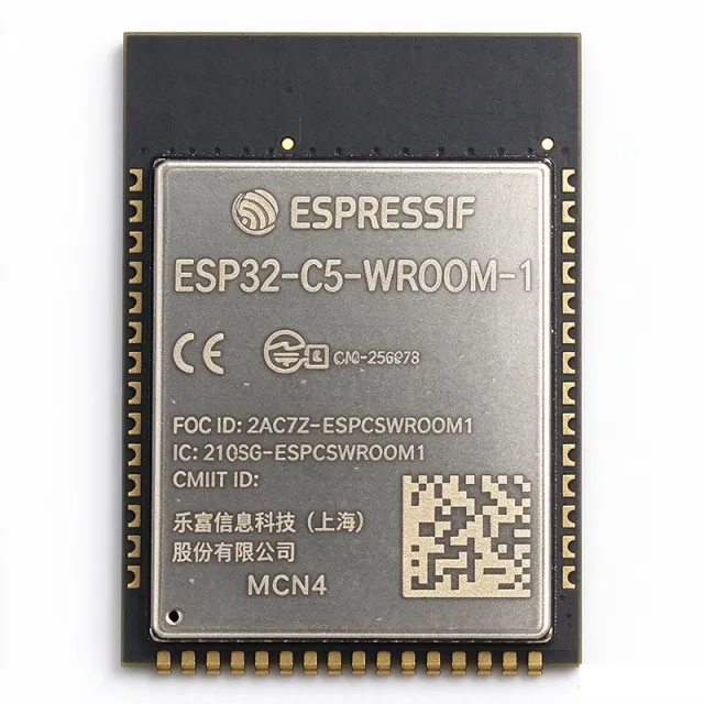
ESP32-C5-WROOM-1 - Dual-Band Wi-Fi 6 BLE Zigbee Module | Espressif
The Espressif ESP32-C5-WROOM-1 is a general-purpose 2.4 and 5 GHz dual-band Wi-Fi 6 (802.11ax) module with Bluetooth 5 (LE), Zigbee, and Thread (IEEE 802.15.4) connectivity, built on a single-core RISC-V MCU clocked up to 240 MHz, housed in a 27.5 x 18 mm surface-mount castellated-pad module with a PCB trace antenna. A wireless module is a pre-certified, fully integrated subassembly that combines a microcontroller SoC, RF front end, antenna, crystal, and flash memory on one small PCB, so designers add connectivity to a product without designing a radio from scratch. In the system hierarchy, a module sits above the SoC level (SoC -> module -> development board) and below complete end products, drastically shortening time-to-market for IoT devices and reducing RF certification effort. Key features include industry-first 5 GHz dual-band Wi-Fi 6 support in a RISC-V MCU, multi-protocol operation spanning 802.11ax, Bluetooth 5 LE, Zigbee, and Thread, and flash options ranging from 4 MB to 32 MB QuadSPI depending on the ordering code. The dual-band capability lets products use the less congested 5 GHz band for higher throughput and lower interference, a decisive advantage in dense smart-home deployments. Technically, the module is built around the ESP32-C5 SoC, which Espressif describes as the industry's first RISC-V MCU supporting 2.4/5 GHz dual-band Wi-Fi 6 alongside IEEE 802.15.4. This allows Matter-over-Thread and Zigbee 3.0 devices to coexist with Wi-Fi on a single chip, simplifying border-router and hub architectures. The ambient operating temperature range is -40 to +85 C per the module datasheet family table. Typical applications include smart-home devices (Matter, Thread, Zigbee), industrial automation nodes, healthcare and consumer electronics, where the rich peripheral set and multi-protocol radio reduce external component count. For design-in, note that strapping pins and the antenna keep-out area must follow Espressif's hardware design guidelines; the module requires a clean 3.3 V supply with adequate peak current capability for Wi-Fi 6 TX bursts. This page synthesizes datasheet specifications, family variants, drop-in alternatives, and practical design guidance not consolidated in the manufacturer datasheet alone.
ESP32-C5-WROOM-1U-N8R8 - Dual-Band Wi-Fi 6 BLE Module | Espressif
The Espressif Systems ESP32-C5-WROOM-1U-N8R8 is a general-purpose 2.4 GHz and 5 GHz dual-band Wi-Fi 6 (802.11ax) module with Bluetooth 5 (LE), Zigbee, and Thread (802.15.4) connectivity, built around a 32-bit RISC-V single-core processor running at up to 240 MHz, with 8 MB Quad SPI flash and 8 MB Quad SPI PSRAM in an 18.0 x 21.2 x 3.3 mm surface-mount package with an IPEX (U.FL) connector for an external antenna. A wireless module is a pre-certified, self-contained circuit board that integrates a microcontroller SoC, RF front end, crystal, flash memory, and antenna interface into a single castellated-edge surface-mount unit. Modules sit above bare SoCs in the electronics hierarchy - embedded system, wireless connectivity module, SoC, silicon - and let designers add certified radio connectivity without in-house RF design or regulatory re-certification. Key features include simultaneous dual-band Wi-Fi 6 support in the 2.412-2.484 GHz and 5.18-5.885 GHz bands, which reduces congestion in dense IoT deployments; 802.15.4 radio for Zigbee and Thread, enabling native Matter and Thread mesh networks; Bluetooth 5 LE for phone provisioning and beacons; and a low-power coprocessor that can monitor peripherals while the main CPU is powered off. At the core is the ESP32-C5 SoC, a single-core 32-bit RISC-V processor clocked up to 240 MHz with a rich peripheral set including SPI, I2C, UART, I2S, PWM, and ADC. The N8R8 variant pairs 8 MB flash with 8 MB PSRAM, providing ample headroom for TLS stacks, display buffers, and Matter applications. Typical applications include smart home hubs that must bridge Wi-Fi, Thread, Zigbee, and BLE simultaneously; industrial automation gateways using the 5 GHz band to avoid 2.4 GHz factory interference; and healthcare or consumer electronics requiring dual-stack wireless provisioning. For design, keep the IPEX antenna feedline at 50 ohms impedance and follow Espressif hardware design guidelines for module keep-out zones. Note that the 1U variant has no onboard PCB antenna, so an external antenna is mandatory. This page synthesizes verified datasheet specifications, drop-in same-family alternatives, and practical design notes not found on distributor listing pages.
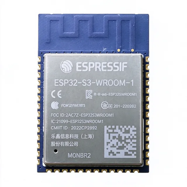
ESP32-S3-WROOM-1 - Wi-Fi 4 + BLE 5 Module, Xtensa LX7 Dual-Core | Espressif
The Espressif ESP32-S3-WROOM-1 is a 2.4 GHz Wi-Fi 4 (802.11 b/g/n) and Bluetooth 5 (LE) MCU module built around the ESP32-S3 series SoC, integrating an Xtensa dual-core 32-bit LX7 microprocessor with vector instructions for AI/ML acceleration. It is supplied as a surface-mount module with on-board PCB antenna, flash up to 16 MB (variant-dependent) and optional PSRAM up to 16 MB, exposed through up to 36 GPIOs. Common ordering codes include N8 (8 MB flash, no PSRAM), N16 (16 MB flash, no PSRAM), N8R8 (8 MB flash, 8 MB PSRAM), and N16R8 (16 MB flash, 8 MB PSRAM). A Wi-Fi + Bluetooth LE module is a self-contained radio subsystem that combines an RF transceiver, baseband, MCU, antenna, and regulatory shielding into a single reflow-solderable package. The module drops by several orders of magnitude of PCB RF design effort for the host product, exposing digital interfaces (UART, SPI, I2C, I2S, USB-OTG) instead of 50-ohm traces. Within the system hierarchy, an ESP32 module sits between the SoC layer and the finished connected-product (module -> wireless SoC -> 32-bit microcontroller -> embedded computing platform). The S3 series specifically adds vector instructions for SIMD-style acceleration of neural-network inference. Key features include hardware acceleration for neural network and signal processing workloads (vector instructions + ESP-DSP/VIEW libraries), integrated 2.4 GHz radio with Wi-Fi 4 (802.11 b/g/n, up to 150 Mbps) + Bluetooth 5 (LE) + Bluetooth Mesh, USB OTG 1.1 with on-chip PHY (no external bridge required), and rich peripherals including SPI, I2S, I2C, UART, ADC, DAC, TWAI (CAN), LCD, camera interface, RMT, pulse counters, and motor PWM. The module supports secure boot, flash encryption, and a hardware crypto accelerator (AES, SHA, RSA, HMAC, digital signature). Architecturally, the LX7 dual-core runs at up to 240 MHz with 512 KB SRAM, 2 MB PSRAM-internal block, and an additional 8 MB external PSRAM on R8 variants. Wi-Fi and Bluetooth share a single antenna through the on-module RF switch; the LX7 + radio architecture is the same die family as the bare ESP32-S3 chip, packaged with crystal, flash, RF matching network, and a copper-pour PCB antenna on the module substrate. Typical applications include AIoT endpoints (voice wake-word, on-device keyword spotting), smart-home hubs with Matter/Bluetooth Mesh, USB-HID devices (the S3 brings native USB-OTG so no UART bridge is needed), wearables with LCD/camera, industrial sensor nodes with TWAI (CAN), and low-cost Wi-Fi/BLE bridge boards. For new designs, observe the strapping-pin (GPIO0/3/45/46) boot-state requirements and ensure the on-module antenna keep-out zone is respected on the host PCB; failure to do so is the most common reason an otherwise-correct ESP32-S3 design has poor RF range. This page synthesizes Espressif datasheet specifications, family-level parametric positioning, and same-footprint alternatives - giving a one-stop overview that individual distributor listings cannot.
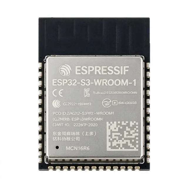
ESP32-S3-WROOM-1-N16R8 - WiFi+BLE 5, 16MB Flash | Espressif
The Espressif Systems ESP32-S3-WROOM-1-N16R8 is a 2.4 GHz Wi-Fi (802.11 b/g/n) and Bluetooth 5 (LE) MCU module built around the ESP32-S3R8 SoC, featuring a dual-core Xtensa 32-bit LX7 processor running at up to 240 MHz, 16 MB quad SPI flash, 8 MB octal PSRAM, and a PCB trace antenna in a surface-mount castellated package of approximately 18 mm x 25.5 mm x 3.1 mm. A Wi-Fi plus Bluetooth LE module is a wireless system-in-package that integrates an RF transceiver, antenna, microcontroller, memory, and power management onto a single certified PCB assembly. Within the hierarchy of wireless connectivity solutions, such modules sit above bare SoCs (which require RF design expertise) and below complete single-board computers, making them the standard choice for IoT product integration. Key differentiating features include 8 MB of octal SPI PSRAM for AI workloads, vector instructions for neural network computing acceleration, 36 GPIOs, and the ESP32-S3's rich peripheral set including SPI, I2S, I2C, UART, RMT, and a 14-bit LCD camera interface. The dual-core LX7 architecture allows one core to run the wireless protocol stack while the other executes user applications. Technically, the module integrates the ESP32-S3R8 chip with the PSRAM die stacked inside, a 40 MHz crystal, flash memory, and a PCB antenna with matching network. The AI acceleration makes it suitable for wake word detection, speech command recognition, and camera-based face detection at the edge. Typical applications include AIoT devices, smart speakers, home automation hubs, industrial sensor gateways, and battery-powered voice assistants. Design considerations: respect strapping pin configurations (IO0, IO45, IO46) at boot, and note peak Wi-Fi TX currents near 350 mA require a low-ESR 3.3 V supply with adequate decoupling. This page synthesizes distributor availability, same-family drop-in variants, and practical design notes not found in the manufacturer datasheet.
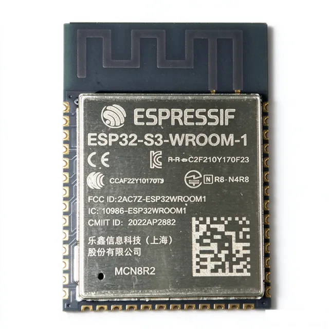
ESP32-S3-WROOM-1-N8 - WiFi/BLE5 MCU Module 8MB Flash | Espressif
The Espressif Systems ESP32-S3-WROOM-1-N8 is a generic Wi-Fi + Bluetooth LE MCU module built around the dual-core ESP32-S3 SoC, offering 8 MB of Quad SPI flash, 2.4 GHz Wi-Fi 802.11 b/g/n and Bluetooth 5 connectivity in a 25.5 x 18 mm surface-mount module with a PCB trace antenna. A Wi-Fi/BLE MCU module integrates a microcontroller, radio, RF matching network, antenna, flash memory and crystal oscillator onto a single certified surface-mount assembly. In the system hierarchy it sits above the bare SoC (here the ESP32-S3 chip) and below finished boards such as development kits, serving as the compute-plus-connectivity engine of an IoT device. Key differentiating features include a dual-core 32-bit LX7 processor that accelerates neural network computing and signal processing workloads, 8 MB of on-module SPI flash for code and assets, and Bluetooth 5 LE with long-range support. The module exposes a rich set of peripherals, making it suitable for designs that need both wireless connectivity and local AI inference such as wake word detection. Architecturally, the ESP32-S3 SoC combines two processor cores with vector instructions for machine-learning workloads, integrated Wi-Fi and BLE radios, and peripherals including SPI, I2C, UART, I2S, and native USB. The on-module PCB antenna and RF front end remove the need for external RF design, while flash is connected over Quad SPI for fast code execution from cache. Typical applications include AIoT devices performing wake word detection and speech command recognition, smart home and industrial IoT nodes, and human-interface products that leverage the ESP32-S3 USB and display-oriented peripherals. The 2.4 GHz radio and 8 MB flash cover the memory and connectivity needs of most connected-device firmware stacks. Design considerations: verify memory-map configuration for Quad SPI flash, respect strapping-pin requirements at boot, and provide clean 3.3 V power with adequate decoupling for Wi-Fi transmit bursts. This page adds value beyond the manufacturer datasheet by synthesizing distributor availability data, same-footprint memory variants for drop-in flexibility, comparison tables, and practical design notes in one place.
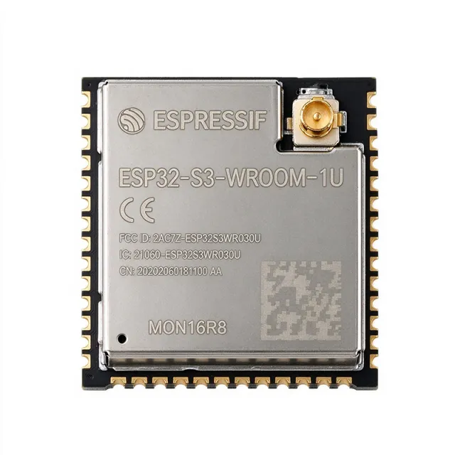
ESP32-S3-WROOM-1U - WiFi/BLE 5 Module, ESP32-S3 | Espressif
The Espressif Systems ESP32-S3-WROOM-1U is a generic 2.4 GHz Wi-Fi (802.11 b/g/n) and Bluetooth 5 (LE) MCU module built around the ESP32-S3 series SoC, featuring an Xtensa dual-core 32-bit LX7 processor, support for up to 16 MB flash and up to 8 MB PSRAM, and a U.FL connector for external antennas instead of an on-board PCB antenna. A Wi-Fi + Bluetooth LE MCU module is a surface-mount system-in-package that integrates a wireless SoC, flash memory, crystal oscillator, RF matching network, and power management onto a single castellated-edge PCB. Modules occupy the top of the embedded wireless hierarchy - above bare SoCs, which require RF layout expertise, and below finished development boards - and are the standard building block for IoT products that need certified radio performance without in-house RF engineering. Key features of the ESP32-S3-WROOM-1U include up to 36 GPIOs with a rich peripheral set, hardware acceleration for neural network computing and signal processing workloads, native USB OTG on the ESP32-S3 SoC, and Bluetooth 5 LE long-range support. The U.FL (IPEX) antenna connector allows designers to place the antenna remotely or use higher-gain external antennas, which distinguishes it from the PCB-antenna ESP32-S3-WROOM-1 sibling in the same series. Technically, the module is built around the ESP32-S3 SoC with dual-core LX7 CPUs clocked for general-purpose embedded workloads, integrating AI vector instructions that offload edge-inference tasks. The RF front end is pre-matched and pre-certified, dramatically reducing design risk compared to a discrete ESP32-S3 chip implementation where antenna matching and regulatory testing fall on the designer. Typical applications include AIoT edge devices, voice assistant endpoints, smart-home controllers, industrial sensor gateways, and any product requiring an external or remote-mounted antenna such as metal-enclosure designs that route the U.FL cable to an external bulkhead antenna. A key design consideration is strapping-pin handling: GPIO0, GPIO45, and GPIO46 configure boot mode and flash voltage at reset, so external circuits on these pins must respect datasheet pull-up/pull-down requirements to avoid boot failures. This page synthesizes the Espressif datasheet, distributor availability, drop-in family alternatives, and practical design notes not found on the manufacturer product page alone.
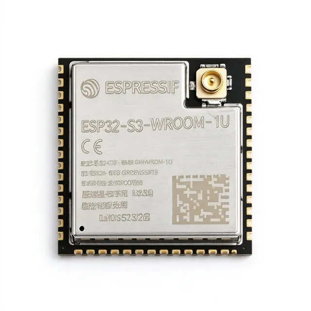
ESP32-S3-WROOM-1U-N16R2 - WiFi/BLE 5 Module 16MB Flash | Espressif
The Espressif Systems ESP32-S3-WROOM-1U-N16R2 is a Wi-Fi + Bluetooth LE MCU module built around the ESP32-S3R2 SoC, featuring a dual-core Xtensa LX7 CPU clocked at up to 240 MHz, 16 MB of quad SPI flash, and 2 MB of integrated quad SPI PSRAM, housed in a 19.2 x 18 x 3.2 mm SMD package with a U.FL (IPEX) antenna connector instead of an onboard PCB antenna. A Wi-Fi + Bluetooth LE MCU module is a system-in-package device that integrates a wireless SoC, flash memory, crystal oscillator, RF matching network, and power management into a single surface-mount unit. Within the embedded hierarchy, it sits above bare microcontrollers and below finished boards, functioning as the wireless connectivity and compute heart of an Internet of Things (IoT) node, edge-AI endpoint, or connected industrial device. Key differentiating features include the N16R2 memory configuration (16 MB flash + 2 MB PSRAM), the external-antenna U.FL footprint that lets designers place the antenna optimally inside a metal or RF-constrained enclosure, and the ESP32-S3 SoC's vector instructions for neural network computing and signal processing acceleration. The module supports Wi-Fi 802.11 b/g/n in the 2.4 GHz band and Bluetooth 5 LE, and exposes a rich peripheral set including SPI, I2C, I2S, UART, PWM, and native USB OTG. The underlying ESP32-S3R2 integrates the 2 MB PSRAM die inside the module stack, allowing quad SPI PSRAM access for memory-hungry workloads such as voice buffers, image frames, and TinyML models. The dual-core LX7 architecture lets one core handle the wireless protocol stack while the second executes application code, improving real-time determinism. Typical applications include wake word detection and speech command recognition, AIoT gateways, face recognition terminals, smart-home controllers, and industrial sensors where the external antenna connector simplifies certification and enclosure integration. Design consideration: because the RF path is external, keep the U.FL-to-antenna cable loss below approximately 1 dB and follow Espressif's RF layout guidance for the keep-out area near the connector; also respect the strapping pin states (GPIO0, GPIO45, GPIO46) at power-up for correct boot mode. This page synthesizes distributor pricing, same-family drop-in alternatives, practical design notes, and AI-optimized technical FAQs not found in the manufacturer datasheet alone. Pricing shown is as of 2026-10-11.
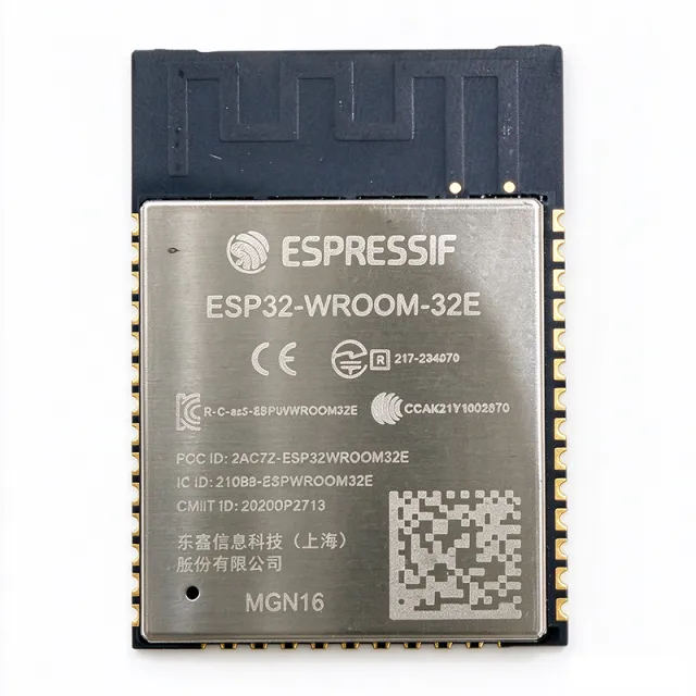
ESP32-WROOM-32E - WiFi + BT 4.2 MCU Module | Espressif
The Espressif Systems ESP32-WROOM-32E is a 2.4 GHz Wi-Fi and Bluetooth/Bluetooth LE combination module built around the ESP32-D0WD-V3 dual-core Xtensa LX6 SoC, delivering up to 240 MHz clock speed, 520 KB SRAM, and 4 MB SPI flash in a compact 18 x 25.5 x 3.1 mm castellated-pad module with an integrated PCB antenna. A Wi-Fi + Bluetooth MCU module is a surface-mount system-in-package that combines a microcontroller, radio transceiver, RF matching network, flash memory, crystal, and antenna onto a single certified PCB assembly. Such modules sit at the top of the embedded hierarchy: semiconductor -> wireless SoC -> RF-certified module -> end IoT device, letting engineers add wireless connectivity without RF design expertise or regulatory re-certification of the radio section. Key differentiating features include dual-core processing that separates Wi-Fi protocol stacks from user applications, 802.11 b/g/n with a data rate up to 150 Mbps, Bluetooth v4.2 BR/EDR and BLE Class 1/2/3 operation, and 38 castellated edge pads that allow both hand soldering and automated assembly. The castellated half-hole pads also enable mounting the module as a sub-PCB on a carrier board. Technically, the ESP32-D0WD-V3 silicon inside is the bug-fixed revision 3 die, improving RF transmit spectrum cleanliness and resolving the well-known strapping-pin flash-voltage issue found in older revision 1 silicon used in the original ESP32-WROOM-32. The module integrates a 40 MHz crystal, flash memory, and a PCB inverted-F antenna tuned during production. Typical applications include low-power sensor networks, voice encoding and MP3 streaming devices, smart-home nodes, and industrial IoT gateways, where integrated dual-radio connectivity and sufficient compute headroom are required in one certified package. For design, respect the strapping pins (GPIO0, GPIO2, GPIO12, GPIO15) at boot and keep the antenna area of the host PCB free of copper and components for best RF performance. This page synthesizes datasheet specifications, drop-in replacement options, and practical design notes not found on standard distributor listings.
ESP32-WROOM-32E-H4 - WiFi BT4.2 Module 4MB | Espressif
The Espressif Systems ESP32-WROOM-32E-H4 is a 2.4 GHz WiFi and Bluetooth 4.2 +BR/EDR/BLE combination module built on the ESP32-D0WD-V3 dual-core Xtensa LX6 SoC with 4 MB of embedded SPI flash, a PCB antenna, and a 25.5 x 18 x 3.1 mm castellated SMD package rated from -40C to +105C. A WiFi module is a self-contained embedded system that integrates a microcontroller, radio transceiver, antenna, flash memory, and power management into a single surface-mount unit, eliminating the RF design effort of discrete solutions. Within the wireless connectivity hierarchy, the ESP32-WROOM-32E-H4 sits at the system-in-package (SiP) module level: SoC (ESP32-D0WD-V3) -> module (WROOM-32E family) -> IoT device. Modules are pre-certified for radio regulatory domains, shortening time to certification for end products. Key features include dual-core 32-bit LX6 CPUs clocked up to 240 MHz, 520 KB on-chip SRAM, 802.11 b/g/n WiFi with up to 150 Mbps PHY rate and -98 dBm receive sensitivity, Bluetooth v4.2 BR/EDR and BLE, and 26 GPIOs with UART, SPI, I2C, SDIO, I2S, PWM, and 12-bit ADC peripherals. The -H4 suffix denotes 4 MB SPI flash; supply range is 3.0 V to 3.6 V with typical TX current around 112 mA and peak around 239 mA at 20 dBm output. The ESP32-D0WD-V3 silicon (ECO V3) incorporates the bug fixes and cleaner WiFi RF spectrum of the revised ESP32 revision, improving coexistence and reliability compared with original ESP32-WROOM-32 modules. The onboard PCB antenna is tuned for 2.4 GHz to 2.5 GHz operation, and the metal shield plus castellated edge pads simplify reflow assembly onto standard PCB footprints. Typical applications include smart-home devices and sensors, industrial automation and control nodes, and battery-powered IoT endpoints where integrated dual-protocol wireless reduces BOM cost and development risk. A key design consideration: the module is 3.3 V only - do not feed 5 V logic into GPIOs without level shifting, and keep copper keep-out clearance under and around the PCB antenna per Espressif hardware design guidelines. This page adds value beyond the datasheet by synthesizing distributor pricing tiers, drop-in same-footprint alternatives across flash densities, and practical engineering design notes in one place.