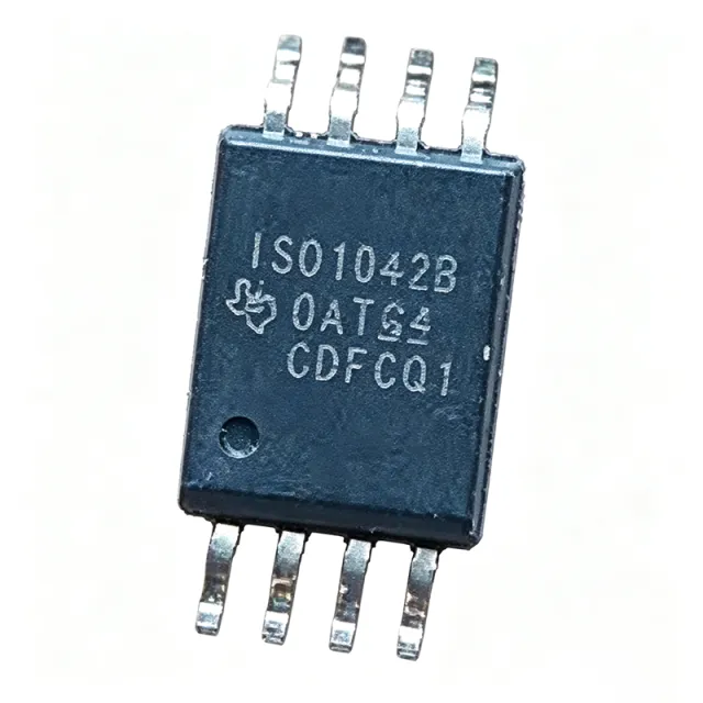
ISO1042BDWVR - Isolated CAN FD Transceiver 5Mbps 70V | TI
N.º de pieza: ISO1042BDWVR ✓ Activo| Cant. | Precio unitario | Total |
|---|---|---|
| 1 | $3.05 | $3,05 |
| 10 | $2.74 | $27,40 |
| 100 | $2.31 | $231,00 |
| 500 | $1.92 | $960,00 |
| 1.000 | $1.58 | $1.580,00 |
ISO1042BDWVR Descripción general
A CAN transceiver is the physical-layer interface device that translates logic-level signals from a CAN controller into differential bus signals (CANH/CANL) and back. Within the system hierarchy it sits between the protocol controller and the twisted-pair bus, and isolated variants like the ISO1042 belong to the broader class of digital-isolator-based interface ICs used in industrial and automotive networks.
Key features include 70-V bus fault protection (far beyond the -27V to 40V tolerance of typical transceivers), a 5 Mbps flexible data rate for CAN FD frames, and logic-side supply flexibility from 1.8V to 5.5V, allowing direct connection to low-voltage microcontrollers without level shifting. Integrated bus-pin ESD protection of +/-16 kV HBM, thermal shutdown, and dominant-timeout functions further harden the interface.
Architecturally, the device integrates the TX and RX signal isolation channels across TI's capacitive isolation barrier plus the CAN bus driver/receiver in one package, eliminating a separate digital isolator in front of a standard transceiver. The low loop delay of 152 ns supports longer bus lengths and faster arbitration in CAN FD communication, and the device meets ISO11898-2 (2016) standard specifications.
Typical applications include industrial automation and motor drive networks, building automation, NVIDIA Jetson-style embedded compute platforms requiring a CAN FD isolator, automotive body electronics (the ISO1042BQDWVRQ1 variant), and medical equipment needing safety isolation between controller and bus.
For design, maintain creepage and clearance around the isolation barrier in PCB layout, supply the logic side at 1.8V or 5.5V as specified, and place the 120-ohm bus termination per standard CAN practice.
This page synthesizes distributor pricing, drop-in alternatives, and practical design notes not found in the manufacturer datasheet. Pricing at authorized distributors starts near $0.77 as of 2026-09-01.
Alternativas directas para ISO1042BDWVR — mismo encapsulado, compatible pin a pin. Se excluyen las piezas de otro encapsulado que requieren retrabajo de la PCB.
Variantes de esta serie
Modelos de la misma serie compatibles directamente con ISO1042BDWVR (mismo factor de forma y huella) — difiere en Package, Product Type, Bus Fault Protection, Logic-Side Supply (VCC1), Protocol.
Herramienta de comparación rápida — seleccione piezas alternativas para compararlas lado a lado:
ISO1042DWVR
✅ Sustitución directa📋 Alternativa de referencia (no en el catálogo)
ISO1042BQDWVRQ1
✅ Sustitución directa ⚠️ Especificaciones sin verificar✓ En stock
$1.5052 / unidad
Ver hoja de datos →ISO1042BDWVR Especificaciones
| Product Type | Isolated CAN transceiver |
| Protocol | CAN / CAN FD (ISO11898-2 2016) |
| Velocidad de datos | Up to 5 Mbps (flexible data rate) |
| Bus Fault Protection | 70 V |
| Working Isolation Voltage | 1060 Vrms |
| Isolation Type | Basic isolation, capacitive barrier |
| Logic-Side Supply Range (VCC1) | 1.8 V to 5.5 V |
| Loop Delay | 152 ns |
| ESD Protection (Bus Pins) | +/-16 kV HBM |
| Duplex | Half duplex, 1 driver / 1 receiver |
| Temperatura de funcionamiento | -40C to +125C |
| Encapsulado | 8-pin SOIC (DWV), wide body |
| Tipo de montaje | Surface Mount |
| Protection Features | Thermal shutdown, bus fault protection |
| Estado RoHS | Compliant |
Configuración de pines de ISO1042BDWVR
| Pin 1 | VCC1 — Logic-side supply (1.8 V to 5.5 V) |
| Pin 2 | GND1 — Logic-side ground reference |
| Pin 3 | TXD — Transmit data input from CAN controller |
| Pin 4 | RXD — Receive data output to CAN controller |
| Pin 5 | GND2 — Bus-side ground reference (isolated) |
| Pin 6 | CANL — CAN low differential bus line |
| Pin 7 | CANH — CAN high differential bus line |
| Pin 8 | VCC2 — Bus-side supply (isolated) |
Aplicaciones típicas
ISO1042BDWVR es adecuado para 6 aplicacións: Industrial Automation and Motor Drives, Embedded Compute and Robotics Platforms, Automotive Body Electronics, Building Automation Networks, Medical Equipment Isolation, Test and Measurement Instrumentation.
Industrial Automation and Motor Drives
The ISO1042BDWVR fits industrial CAN networks where the transceiver sits at the boundary between an isolated controller domain and a shared fieldbus. Its 70-V bus fault protection survives wiring errors and motor-drive transients that would damage conventional -27V to 40V rated transceivers, while the 1060 Vrms working isolation blocks ground loops between drive chassis and controller grounds. With 5 Mbps CAN FD support and a 152 ns loop delay, it handles high-speed motion control frames, and the 1.8V to 5.5V logic supply range connects directly to modern 3.3V MCUs. Place a 120-ohm termination at each bus end and maintain creepage around the isolation barrier on the PCB for reliable operation in electrically noisy industrial cabinets.
Recomendado
Embedded Compute and Robotics Platforms
High-performance embedded compute platforms such as NVIDIA Jetson require a CAN FD isolator for robotics peripherals, and the ISO1042BDWVR is a TI-recommended choice in this exact use case per TI E2E forum guidance. The 5 Mbps flexible data rate matches CAN FD data phases used by modern robot bus architectures, while the 152 ns loop delay preserves bit timing margin at high data rates. The 1.8V-capable logic side interfaces directly with low-voltage SoC GPIO banks without level shifting, and 70-V bus fault protection guards against wiring faults in cable harnesses. Galvanic isolation prevents ground loops between the compute module and motor driver grounds, improving EMI robustness in dense robotics assemblies.
Recomendado
Automotive Body Electronics
For body control modules, lighting networks, and gateways, the automotive-qualified family member ISO1042BQDWVRQ1 provides the same 70-V bus fault protection and 5 Mbps CAN FD performance with AEC-Q100 qualification in the identical 8-SOIC DWV footprint, enabling PCB reuse. The wide -40C to +125C operating range covers under-hood and exterior lamp environments, and the 1060 Vrms working isolation separates noisy 12V/48V domains from sensitive controller logic. TI Q1-family transceivers such as TCAN1042VDRQ1 and SN65HVD230QDRQ1 cover non-isolated nodes on the same network. The dominant timeout and thermal shutdown features prevent a single faulted node from stalling the entire vehicle bus during fault conditions.
Recomendado
Building Automation Networks
Building automation and HVAC control systems run CAN or CAN FD segments across long cable runs where wiring faults and induced surges are common. The ISO1042BDWVR's 70-V bus fault protection tolerates miswiring to 24V auxiliary supplies, a frequent field failure mode for standard transceivers, while the isolation barrier separates field wiring grounds from the controller. The 5 Mbps data rate supports future-proof CAN FD upgrades of legacy 125 kbps to 1 Mbps segments, and the 152 ns loop delay keeps propagation delay low across multi-drop networks. Its +/-16 kV HBM ESD rating on bus pins handles handling and installation transients, reducing warranty returns in retrofit installations.
Recomendado
Medical Equipment Isolation
Patient-connected and laboratory medical equipment requires galvanic isolation between the controller electronics and externally accessible communication ports, and the ISO1042BDWVR provides 1060 Vrms working isolation with basic isolation ratings in a compact 8-SOIC package. The capacitive isolation barrier blocks ground potential differences between equipment racks and isolated patient modules, while the 70-V bus fault protection covers defibrillator-style transient environments better than standard 40-V rated parts. The 5 Mbps CAN FD rate supports high-throughput data acquisition nodes, and the low 152 ns loop delay keeps deterministic real-time control loops closed across the barrier. Maintain datasheet creepage and clearance rules in PCB layout to preserve the isolation rating.
Recomendado
Test and Measurement Instrumentation
Bench instruments, CAN bus analyzers, and HIL test fixtures benefit from the ISO1042BDWVR because its isolation protects the host instrument from unknown or faulted devices under test. The 70-V bus fault rating lets an analyzer survive connections to miswired harnesses, and the 1060 Vrms isolation prevents ground loop currents when testing equipment referenced to different grounds. Support for the full 5 Mbps CAN FD rate ensures the instrument can exercise modern automotive and industrial networks, while 1.8V to 5.5V logic-side flexibility matches any host interface voltage. TI's ISO1042DWEVM evaluation module provides a ready-made reference layout for integrating the transceiver into new instrument designs.
Recomendado
Resumen de productos recomendados
Datos de referencia de ingeniería para ISO1042BDWVR — comparación, orientación de diseño e información de cumplimiento.
Guía de selección
Comparación con alternativas
| Parámetro | Este producto | ISO1042DWVR | ISO1042BQDWVRQ1 |
|---|---|---|---|
| Package | 8-SOIC (DWV) | 8-SOIC (DWV) - same | 8-SOIC (DWV) - same |
| Brand | Texas Instruments | Texas Instruments | Texas Instruments |
| Bus Fault Protection | 70 V | Standard grade (reduced) | 70 V |
| Data Rate | 5 Mbps CAN FD | 5 Mbps CAN FD | 5 Mbps CAN FD |
| Working Isolation Voltage | 1060 Vrms | 1060 Vrms | 1060 Vrms |
| Logic Supply Range | 1.8 V to 5.5 V | 1.8 V to 5.5 V | 1.8 V to 5.5 V |
| AEC-Q100 Qualified | No | No | Yes (Q1) |
| Operating Temperature | -40C to +125C | -40C to +125C | -40C to +125C |
| Loop Delay | 152 ns | 152 ns | 152 ns |
Diferenciadores clave
- 70-V bus fault protection (frente a ISO1042DWVR)
- CAN FD 5 Mbps with low 152 ns loop delay (frente a ISO1050)
- AEC-Q100 path without redesign (frente a ISO1042BQDWVRQ1)
Notas de diseño
Maintain the datasheet creepage and clearance distances across the isolation barrier between the logic-side (pins 1-4) and bus-side (pins 5-8) domains. Route no logic-side traces under the bus-side region of the DWV package, and keep the area under the package free of internal-layer copper spanning both grounds. This preserves the 1060 Vrms working isolation rating and prevents barrier degradation during reflow and over product lifetime.
Decouple VCC1 and VCC2 each with a 0.1 uF ceramic capacitor placed within 2 mm of the pins, plus a bulk 1 uF to 10 uF capacitor per side. The logic side may run from 1.8 V, 3.3 V, or 5 V - confirm your MCU supply before wiring, since TXD thresholds scale with VCC1. On the bus side, size the 5 V supply for peak transmit current of the dominant state plus margin for bus fault events.
Do not assume pin compatibility with ISO1050 - per TI E2E forum confirmation, ISO1050 is not pin-to-pin compatible with ISO1042, so footprints are not interchangeable. Also verify the B-grade 70-V fault rating requirement: the ISO1042DWVR standard grade drops into the same footprint but does not provide the 70-V rating. Terminate the bus with a single 120-ohm resistor at each physical bus end, not at every node.
The 152 ns loop delay leaves timing margin for CAN FD at 5 Mbps, but total loop delay also includes the controller and any additional isolation in the RX path. Estimate the full round-trip delay budget before finalizing the bit-rate prescaler settings, and route TXD/RXD traces short and away from the CANH/CANL differential pair to minimize coupling between logic and bus domains.
Información de cumplimiento
RoHS compliant per TI product listing. Not AEC-Q100 qualified - use ISO1042BQDWVRQ1 for automotive. REACH and halogen-free status not stated in provided data.







