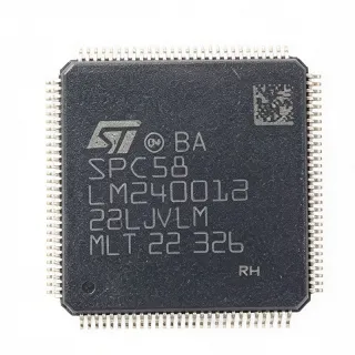
LPC1813JBD144551 - 32-bit Cortex-M3 MCU | NXP | LQFP-144
N.º de pieza: LPC1813JBD144551 ✓ ActivoLPC1813JBD144551 Descripción general
A microcontroller is a programmable system-on-chip that integrates a processor core, memory, clock circuitry, communication interfaces, timers, and general-purpose input/output ports. The ARM Cortex-M3 class belongs to the microcontroller hierarchy and is commonly used for real-time embedded control. Within that hierarchy, the LPC1813 combines general-purpose processing with higher-speed serial connectivity than a basic Cortex-M design, while its 144-pin package provides extensive external interface access.
The principal specifications include a 32-bit Cortex-M3 core, 512 KB of flash memory for firmware, 104 KB of SRAM for working data, and an LQFP-144 surface-mount package. The 512 KB of flash supports a substantially larger embedded program than small general-purpose MCUs, while the 104 KB SRAM can accommodate network buffers, protocol state, display or communication data, and real-time application variables.
Its feature set is positioned for connected embedded systems. Ethernet support is particularly useful for industrial terminals, network controllers, gateways, and embedded equipment that must communicate over an Ethernet network. The large pin count also supports multiple external interfaces and dedicated I/O, helping designers separate communication, control, sensing, and debug functions on a complex board.
Typical applications include industrial Ethernet controllers, communications gateways, motor and motion-control equipment, data acquisition systems, and embedded network appliances. In each case, the MCU can execute control logic while Ethernet handles higher-level connectivity. The LQFP-144 footprint offers ample pins for external transceivers, memories, sensors, isolation interfaces, and power-management components.
Board design should prioritize stable power and grounding, correct decoupling, signal integrity around Ethernet and high-speed digital interfaces, and careful programming of unused pins. Confirm the complete LPC1813 pin-description table, alternate-function settings, and exposed-pad requirements in the NXP LPC1813JBD144 datasheet before releasing the PCB layout.
This product page consolidates the verified LPC1813JBD144 manufacturer specifications, package information, sourcing links, practical integration guidance, and same-footprint family options into one engineering-focused reference for designers evaluating the LPC1813JBD144551.
Alternativas directas para LPC1813JBD144551 — mismo encapsulado, compatible pin a pin. Se excluyen las piezas de otro encapsulado que requieren retrabajo de la PCB.
Variantes de esta serie
Modelos de la misma serie compatibles directamente con LPC1813JBD144551 (mismo factor de forma y huella) — difiere en Package.
LPC1813JBD144E
✅ Sustitución directaConsulte el precio
Ver hoja de datos →LPC1813JBD144E
✅ Sustitución directaConsulte el precio
Ver hoja de datos →LPC1813JBD144551 Valores máximos y características eléctricas
| Microcontroller Type | 32-bit ARM Cortex-M3 microcontroller |
| Processor Core | ARM Cortex-M3 |
| Architecture | 32-bit |
| Flash Memory | 512 KB |
| SRAM | 104 KB |
| Maximum Flash in LPC1813 Family | 1 MB |
| Maximum SRAM in LPC1813 Family | 136 KB |
| Ethernet Support | Yes |
| Encapsulado | LQFP-144 |
| Tipo de montaje | Surface mount |
| Recuento de pines | 144 pins |
Guía de configuración de pines de LPC1813JBD144551 lqfp-144
Configuración de pines para LPC1813JBD144551 (encapsulado lqfp-144). Este CI digital incluye GPIO, interfaces de comunicación (UART, SPI, I2C) y pines de alimentación. Consulte la hoja de datos del fabricante para conocer las funciones alternativas de los pines y las opciones de configuración. Esencial para el diseño de sistemas embebidos y el diseño de PCB.
No hay datos detallados de patillaje disponibles para LPC1813JBD144551.
Consulte la hoja de datos para ver la configuración completa de patillas.
Aplicaciones típicas
LPC1813JBD144551 es adecuado para 6 aplicacións: Industrial Ethernet Controllers, Industrial Communications Gateways, Motor and Motion Control, Data Acquisition Systems, Networked Test and Measurement Equipment, Connected Building and Facility Equipment.
Industrial Ethernet Controllers
The LPC1813JBD144551 fits industrial Ethernet controllers because it combines a 32-bit ARM Cortex-M3 processor with 512 KB of flash, 104 KB of SRAM, Ethernet support, and 144 package pins. The processor can handle protocol processing and local control tasks, while the large SRAM provides room for packet buffers and network state. Its LQFP-144 package also exposes enough pins for an Ethernet PHY, isolation components, status indicators, and industrial I/O. A typical design uses the MCU beside an external Ethernet transceiver, with careful separation between analog, digital, and network-related circuitry.
Recomendado
Industrial Communications Gateways
The LPC1813JBD144551 is suitable for an industrial communications gateway that must combine network connectivity with multiple embedded control functions. Its 512 KB of flash accommodates gateway firmware, protocol stacks, configuration data, and update logic, while 104 KB of SRAM supports active sessions and protocol buffering. The 144-pin package can accommodate multiple UART, SPI, and digital-control connections alongside Ethernet. Compared with a compact 32-pin MCU, this device reduces the need for external I/O expanders and provides more parallel interface capacity for equipment that bridges Ethernet with local sensors or actuators.
Recomendado
Motor and Motion Control
The LPC1813JBD144551 can serve as the supervisory controller in a motor-control system where the MCU handles command processing, interlocks, diagnostics, and communications. Its 32-bit Cortex-M3 architecture supports responsive embedded tasks, and the LQFP-144 package offers a broad pin budget for encoders, control signals, fault inputs, and external interfaces. The 512 KB flash and 104 KB SRAM are useful when control, networking, and field-service functions share one processor. Power-stage design remains separate, so the MCU should be paired with appropriately rated drivers, protection circuitry, and isolated sensing where required.
Recomendado
Data Acquisition Systems
The LPC1813JBD144551 fits distributed data-acquisition equipment requiring local sampling control, buffering, and network reporting. Its 512 KB flash can hold acquisition firmware and calibration logic, while 104 KB of SRAM can temporarily hold process variables before transmission. The large LQFP-144 package provides numerous pins for sensor interfaces, digital inputs, communication ports, and status controls. Engineers should use the datasheet to map analog and digital functions, then preserve analog-signal separation on the PCB. Ethernet connectivity can centralize configuration and monitoring without requiring a separate communications processor.
Recomendado
Networked Test and Measurement Equipment
The LPC1813JBD144551 is appropriate for networked test and measurement equipment that combines real-time acquisition, configuration management, and Ethernet reporting. The 32-bit Cortex-M3 core provides a capable embedded control platform, and the 512 KB flash supports instrument firmware, calibration tables, and protocol handlers. With 104 KB SRAM, the controller can manage acquisition buffers while maintaining network activity. The LQFP-144 package provides a practical balance between interface access and board area, supporting front-panel signals, external memories, transceivers, and synchronization features without the complexity of a very large fine-pitch package.
Recomendado
Connected Building and Facility Equipment
The LPC1813JBD144551 can support connected building equipment such as room controllers, access-control nodes, environmental controllers, or equipment gateways. Its Ethernet capability allows remote management and status reporting, while the 32-bit processor performs local control when connectivity is unavailable. The 512 KB flash and 104 KB SRAM provide room for networking, logging, and multiple peripheral tasks in a single device. The LQFP-144 footprint is useful when a design requires many discrete I/O signals for relays, sensors, indicators, and field buses. The final design must include suitable isolation, surge protection, and environmental controls.
Recomendado
Resumen de productos recomendados
Datos de referencia de ingeniería para LPC1813JBD144551 — comparación, orientación de diseño e información de cumplimiento.
Guía de selección
Comparación con alternativas
| Parámetro | Este producto | LPC1813JBD144 | LPC1813JBD144E |
|---|---|---|---|
| Brand | NXP Semiconductors | NXP Semiconductors | NXP Semiconductors |
| Package | LQFP-144 | LQFP-144 | LQFP-144 |
| Processor Core | ARM Cortex-M3, 32-bit | ARM Cortex-M3, 32-bit | ARM Cortex-M3, 32-bit |
| Ethernet Support | Yes | Yes | Yes |
| Pin Count | 144 pins | 144 pins | 144 pins |
| Order Suffix Configuration | LPC1813JBD144551 | Base LPC1813JBD144 order code | E-suffixed LPC1813JBD144 order code |
Diferenciadores clave
- Large memory configuration within the same LQFP-144 footprint (frente a LPC1813JBD144)
- Network-capable Cortex-M3 platform (frente a LPC1813JBD144E)
- Broad peripheral integration for complex embedded equipment (frente a STM32L152C8T6TR)
Notas de diseño
Plan the LPC1813JBD144551 power tree from the NXP LPC1813JBD144 electrical requirements. Place required bulk and high-frequency decoupling capacitors close to the device's supply and ground pins, provide a stable source for the Ethernet PHY and other peripherals, and keep analog or sensitive measurement supplies on appropriately filtered branches. Use the datasheet pin table to identify all supply terminals rather than assuming that every rail has the same voltage.
Use the manufacturer LQFP-144 land pattern and pin numbering when laying out the PCB. Confirm exposed-pad, thermal, and ground-connection requirements in the package drawing. Preserve clear copper for thermal dissipation if an exposed pad is specified, and route high-current Ethernet magnetics or other power-conversion components away from sensitive microcontroller signals. A package-family match does not eliminate the need to verify footprint dimensions.
Separate Ethernet and other high-speed communication paths from clock, sensing, and control signals. Follow the reference layout and component placement used by the manufacturer application information, including the placement of the Ethernet PHY and its magnetic interface. Provide an uninterrupted ground reference, avoid routing communication signals beneath isolation barriers or noisy regulators, and apply differential-pair geometry consistently when the selected Ethernet interface requires it.
Do not treat LPC1813JBD144, LPC1813JBD144E, and LPC1813JBD144551 as interchangeable solely because they share the LQFP-144 package. Review the ordering suffix for temperature grade, packing, qualification, and lifecycle terms, then compare the complete datasheet pin table and errata. Also confirm that existing firmware supports the selected device revision and that all bootloader, clock, debug, and Ethernet peripheral assignments remain unchanged.
Información de cumplimiento
The product listings do not explicitly state RoHS, REACH, AEC-Q100, lead-free, halogen-free, or conflict-minerals status for this exact suffix. The device is a general-purpose microcontroller rather than an explicitly automotive-qualified variant.