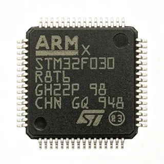
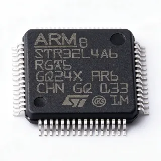
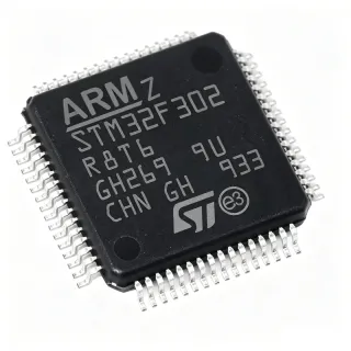
STM32L452RET6 - Ultra-Low-Power Cortex-M4 MCU 80MHz 512KB | ST
N.º de pieza: STM32L452RET6 ✓ Activo| Cant. | Precio unitario | Total |
|---|---|---|
| 1 | $7.82 | $7,82 |
| 10 | $7.04 | $70,40 |
| 100 | $6.26 | $626,00 |
| 500 | $5.55 | $2.775,00 |
| 1.000 | $4.95 | $4.950,00 |
STM32L452RET6 Descripción general
What is an ultra-low-power ARM Cortex-M4 microcontroller? It is a 32-bit processor core designed for embedded systems that balances computational performance with exceptionally low energy consumption. The Cortex-M4 includes a single-precision floating-point unit (FPU) and DSP extensions, enabling efficient math-intensive workloads. In the system hierarchy, a microcontroller (MCU) is a complete computer-on-a-chip integrating CPU, memory, and peripherals, and belongs to the embedded processor category within the broader semiconductor landscape. The STM32L4 series specifically targets energy-constrained applications, extending battery life in portable, wearable, and IoT devices.
Key features of the STM32L452RET6 include seven low-power modes (Sleep, Low-power run, Low-power sleep, Stop 0/1/2, Standby, Shutdown), a 12-bit ADC with hardware oversampling, a 12-bit DAC, two comparators, and an operational amplifier. The device also integrates a true random number generator (TRNG), AES-256 hardware crypto accelerator, secure firmware install, and a 96-bit unique ID. Communication interfaces include USB 2.0 Full-Speed Device, three USARTs, two UARTs, three I2C, three SPI, one CAN, and one SDMMC.
Technically, the STM32L452RET6 is built on a low-leakage 90 nm process and supports up to 100 DMIPS / 273 CoreMark. The integrated SMPS step-down converter generates the core voltage internally, further reducing active current. A flexible memory protection unit (MPU), FSMC external memory controller, and Quad-SPI (in higher-density siblings) support external memories. The device operates across -40 C to +85 C (or +125 C with the '6' high-temp suffix variant).
Typical applications include industrial sensors, smart meters, healthcare devices, wearable electronics, asset trackers, and IoT endpoints. Its combination of ultra-low quiescent current, Cortex-M4 DSP performance, and rich analog peripherals makes it ideal for battery-powered metering, medical wearables, and remote sensor nodes.
When designing, leverage Stop 2 mode with RTC for periodic wake-up duty cycles, place 100 nF decoupling on every VDD/VSS pair, and use STM32CubeMX + STM32CubeIDE for clock tree configuration, peripheral init, and power-mode tuning.
This page synthesizes distributor pricing, drop-in alternatives, and practical design notes not found in the manufacturer datasheet.
Alternativas directas para STM32L452RET6 — mismo encapsulado, compatible pin a pin. Se excluyen las piezas de otro encapsulado que requieren retrabajo de la PCB.
Variantes de esta serie
Modelos de la misma serie compatibles directamente con STM32L452RET6 (mismo factor de forma y huella) — difiere en Operating Temperature Range, ADC, SRAM, DAC, Package.
Herramienta de comparación rápida — seleccione piezas alternativas para compararlas lado a lado:
STM32L452RET6P
✅ Sustitución directa✓ En stock
$5.62 / unidad
Ver hoja de datos →STM32L451RET6
✅ Sustitución directa✓ En stock
$4.38 / unidad
Ver hoja de datos →STM32L476RET6
✅ Sustitución directa✓ En stock
$8.1 / unidad
Ver hoja de datos →STM32L462RET6
✅ Sustitución directa📋 Alternativa de referencia (no en el catálogo)
MKL27Z256VLH4
✅ Sustitución directa📋 Alternativa de referencia (no en el catálogo)
STM32L452RET6 Valores máximos y características eléctricas
| Core | Arm Cortex-M4 with FPU |
| Maximum CPU Frequency | 80 MHz |
| Performance | 100 DMIPS / 273 CoreMark |
| Flash Memory | 512 KB |
| SRAM | 160 KB |
| Supply Voltage Range | 1.71 V to 3.6 V |
| Rango de temperatura de funcionamiento | -40 C to +85 C |
| Shutdown Mode Current | 22 nA (5 wakeup pins) |
| VBAT Mode Current | 145 nA (RTC + 32x32-bit backup registers) |
| ADC | 12-bit, with hardware oversampling |
| DAC | 12-bit |
| Comparators | 2 ultra-low-power |
| Operational Amplifier | 1 on-chip |
| USB | USB 2.0 Full-Speed Device |
| DFSDM | Yes (digital filter for sigma-delta modulators) |
| SMPS Support | Yes (internal step-down core supply) |
| USART/UART | 3 USART + 2 UART |
| SPI | 3 |
| I2C | 3 |
| CAN | 1 (CAN 2.0B) |
| SDMMC | 1 |
| Crypto | AES-256 hardware accelerator |
| TRNG | Yes (true random number generator) |
| Unique ID | 96-bit |
| External Memory Interface | FSMC (SRAM, PSRAM, NOR, NAND) |
| Encapsulado | LQFP-64 (10x10 mm) |
| Tipo de montaje | Surface Mount |
| Estado RoHS | Compliant |
Configuración de pines de STM32L452RET6
| Pin 1 | PC13 — GPIO / Tamper-RTC (pin 1 of LQFP-64) |
| Pin 2 | PC14 — GPIO / OSC32_IN |
| Pin 3 | PC15 — GPIO / OSC32_OUT |
| Pin 4 | VBAT — RTC backup supply |
| Pin 5 | VREF+ — ADC reference positive |
| Pin 6 | VDD — Main digital supply |
| Pin 7 | VSS — Digital ground |
| Pin 8 | VDDA — Analog supply |
| Pin 9 | VSSA — Analog ground |
| Pin 10 | PA0 — GPIO / ADC_IN5 / WKUP1 |
| Pin 11 | PA1 — GPIO / ADC_IN6 |
| Pin 12 | PA2 — GPIO / USART2_TX |
| Pin 13 | PA3 — GPIO / USART2_RX |
| Pin 14 | PA4 — GPIO / SPI1_NSS |
| Pin 15 | PA5 — GPIO / SPI1_SCK |
| Pin 16 | PA6 — GPIO / SPI1_MISO |
| Pin 17 | PA7 — GPIO / SPI1_MOSI |
| Pin 18 | PB0 — GPIO / ADC_IN8 |
| Pin 19 | PB1 — GPIO / ADC_IN9 |
| Pin 20 | PB2 — GPIO |
| Pin 21 | PB10 — GPIO / I2C2_SCL |
| Pin 22 | PB11 — GPIO / I2C2_SDA |
| Pin 23 | VSS — Digital ground |
| Pin 24 | VDD — Main digital supply |
| Pin 25 | PB12 — GPIO / SPI2_NSS |
| Pin 26 | PB13 — GPIO / SPI2_SCK |
| Pin 27 | PB14 — GPIO / SPI2_MISO |
| Pin 28 | PB15 — GPIO / SPI2_MOSI |
| Pin 29 | PA8 — GPIO / RCC_MCO |
| Pin 30 | PA9 — GPIO / USART1_TX |
| Pin 31 | PA10 — GPIO / USART1_RX |
| Pin 32 | PA11 — GPIO / USB_DM |
| Pin 33 | PA12 — GPIO / USB_DP |
| Pin 34 | PA13 — GPIO / SWDIO |
| Pin 35 | VSS — Digital ground |
| Pin 36 | VDD — Main digital supply |
| Pin 37 | PA14 — GPIO / SWCLK |
| Pin 38 | PA15 — GPIO |
| Pin 39 | PB3 — GPIO / SWO |
| Pin 40 | PB4 — GPIO |
| Pin 41 | PB5 — GPIO |
| Pin 42 | PB6 — GPIO / USART1_TX (remap) |
| Pin 43 | PB7 — GPIO / USART1_RX (remap) |
| Pin 44 | BOOT0 — Boot mode select |
| Pin 45 | PB8 — GPIO / I2C1_SCL |
| Pin 46 | PB9 — GPIO / I2C1_SDA |
| Pin 47 | VSS — Digital ground |
| Pin 48 | VDD — Main digital supply |
| Pin 49 | PC0 — GPIO |
| Pin 50 | PC1 — GPIO |
| Pin 51 | PC2 — GPIO |
| Pin 52 | PC3 — GPIO |
| Pin 53 | PC4 — GPIO |
| Pin 54 | PC5 — GPIO |
| Pin 55 | PC6 — GPIO |
| Pin 56 | PC7 — GPIO |
| Pin 57 | PC8 — GPIO |
| Pin 58 | PC9 — GPIO |
| Pin 59 | PA0 (alt) — Reserved / pin 59 mirror on LQFP-64 per ST diagram - not connected on this die |
| Pin 60 | VDD — Main digital supply |
| Pin 61 | VSS — Digital ground |
| Pin 62 | VDD — Main digital supply |
| Pin 63 | VSS — Digital ground |
| Pin 64 | NRST — Reset input (active low) |
Aplicaciones típicas
STM32L452RET6 es adecuado para 6 aplicacións: Industrial Smart Meters, Wearable Health Devices, IoT Sensor Nodes, Portable Medical Instrumentation, Asset Tracking & Logistics, Human-Machine Interface (HMI).
Industrial Smart Meters
The STM32L452RET6 is well-suited for battery-powered electricity, gas, and water meters requiring 10+ year battery life. The Cortex-M4 with FPU handles metering DSP (RMS, harmonics) while DFSDM digitizes external sigma-delta current sensors. Stop 2 mode with RTC enables <3 uA average current at sub-Hz sampling rates, and the 1.71-3.6 V range supports direct LiSOCl2 cell connection. Compared to the STM32L476, the L452's integrated AES-256 allows secure firmware and tamper detection.
Recomendado
Wearable Health Devices
Continuous heart-rate, SpO2, and activity wearables benefit from the L452's 22 nA Shutdown and 145 nA VBAT modes. The integrated 12-bit ADC plus two op-amps drive front-end photodiode conditioning, while DFSDM captures oversampled sensor streams with hardware filtering. The Cortex-M4 FPU accelerates step-counting and biosignal DSP. USB Device supports firmware updates and charging. Choose L452 over STM32L432KCU6 when LQFP-64 GPIO count is needed for multi-sensor boards.
Recomendado
IoT Sensor Nodes
LoRa, BLE, sub-GHz, and Sigfox nodes running on coin cells leverage the L452's seven low-power modes for sub-1 uA idle current. The 80 MHz Cortex-M4 supports LoRaWAN, Matter, or Zigbee stacks on top of DFSDM-based environmental sensor acquisition. AES-256 hardware encryption secures radio payloads without crypto software overhead. The 96-bit unique ID enables per-node key provisioning for fleet management.
Recomendado
Portable Medical Instrumentation
Handheld pulse oximeters, glucose meters, and ECG patches benefit from the L452's combination of analog integration and ultra-low quiescent current. Two on-chip op-amps and a 12-bit ADC with hardware oversampling provide sensor conditioning; the AES-256 block secures patient data. Class-III medical certification is supported by the extended -40 C to +85 C (or +125 C) temperature range and IEC 60730-ready firmware libraries from ST.
Recomendado
Asset Tracking & Logistics
Battery-powered GPS/GNSS asset trackers use the L452's RTC-rich Stop 2 mode plus 5 wakeup pins for duty-cycled positioning. The Cortex-M4 executes cellular or BLE host stacks, AES-256 secures location data, and FSMC supports external NOR flash for geofence logging. The 22 nA Shutdown mode preserves shelf life before deployment. Choose L452 over STM32L412RBT6P if 512 KB Flash is needed for full GNSS firmware.
Recomendado
Human-Machine Interface (HMI)
Industrial HMI panels, e-paper badges, and small touch displays use the L452 to drive segment LCDs (via STM32L4 LCD driver on certain variants), USB HID touchscreens, and capacitive touch sensors. The Cortex-M4 + FPU renders menus and handles gesture recognition, while SDMMC reads images. Compared to STM32F302CBT6, the L452 offers ultra-low idle current for battery-augmented HMI installations.
Recomendado
Resumen de productos recomendados
Datos de referencia de ingeniería para STM32L452RET6 — comparación, orientación de diseño e información de cumplimiento.
Guía de selección
Comparación con alternativas
| Parámetro | Este producto | STM32L452RET6P | STM32L451RET6 | STM32L476RET6 | STM32L462RET6 | MKL27Z256VLH4 |
|---|---|---|---|---|---|---|
| Package | LQFP-64 (10x10 mm) | LQFP-64 (10x10 mm) - same | LQFP-64 (10x10 mm) - same | LQFP-64 (10x10 mm) - same | LQFP-64 (10x10 mm) - same | LQFP-64 (10x10 mm) - same |
| Brand | STMicroelectronics | STMicroelectronics | STMicroelectronics | STMicroelectronics | STMicroelectronics | NXP Semiconductors |
| Core | Arm Cortex-M4 with FPU | Arm Cortex-M4 with FPU | Arm Cortex-M4 with FPU | Arm Cortex-M4 with FPU | Arm Cortex-M4 with FPU | Arm Cortex-M0+ |
| Maximum CPU Frequency | 80 MHz | 80 MHz | 80 MHz | 80 MHz | 80 MHz | 48 MHz |
| Flash Memory | 512 KB | 512 KB | 256 KB | 1 MB | 512 KB | 256 KB |
| SRAM | 160 KB | 160 KB | 160 KB | 128 KB | 160 KB | 32 KB |
| Supply Voltage Range | 1.71 V to 3.6 V | 1.71 V to 3.6 V | 1.71 V to 3.6 V | 1.71 V to 3.6 V | 1.71 V to 3.6 V | 1.71 V to 3.6 V |
| USB Device | USB 2.0 Full-Speed | USB 2.0 Full-Speed | USB 2.0 Full-Speed | USB 2.0 Full-Speed + OTG | USB 2.0 Full-Speed | USB 2.0 Full-Speed |
| DFSDM | Yes | Yes | No | No | Yes | No |
| AES-256 Crypto | Yes (hardware) | Yes | Yes | Yes | Yes + Secure Firmware Install | AES-128 |
Diferenciadores clave
- DFSDM hardware digital filter for sigma-delta modulators (frente a STM32L451RET6)
- Lower Flash density than L476 for cost-sensitive designs (frente a STM32L476RET6)
- AES-256 hardware crypto without Secure Firmware Install overhead (frente a STM32L462RET6)
Notas de diseño
Use Stop 2 mode with RTC for sub-3 uA average current in duty-cycled applications. Wake sources are RTC alarm, 5 WKUP pins, or IWDG. Before entering Stop, ensure USART/SPI are idle and unused peripherals are in reset to minimize leakage. The integrated SMPS generates Vcore internally; bypass VDD_SMPS with a 100 nF + 4.7 uF pair as shown in the reference schematic. Estimated: at 1 Hz wake with 2 ms active execution at 80 MHz, average current is approximately 3 uA from a 3 V supply.
Place a 100 nF decoupling capacitor within 2 mm of every VDD/VDDA pin and a bulk 4.7 uF near the MCU. Use a star-ground topology with separate analog and digital ground planes joined at a single point under the VSSA pin. For USB applications, route the DP/DM pair with 90-ohm differential impedance and keep them short. The LQFP-64 exposed thermal pad (if present on die revision) should be soldered to a 10x10 mm copper pour for 0.5 W continuous dissipation.
Do not leave BOOT0 floating; tie it to GND through a 10 k resistor for normal boot, or to VDD for system memory boot. The NRST pin requires an external 10 k pull-up to VDD and a 100 nF capacitor to ground for reliable reset. PWR_ON pin (if used) must be sequenced after VDD stabilizes. Estimated: a floating BOOT0 may cause 1 in 1000 power-on cycles to enter System Memory bootloader inadvertently.
When routing SDMMC or USB signals, maintain 45-ohm single-ended (90-ohm differential for USB) controlled impedance. Place a 33-ohm series resistor on SDMMC clock close to the MCU. For ADC sampling above 1 MSPS, add a small RC filter (10 ohm + 10 nF) at each analog input to reduce chargekick-back ringing. The VREF+ pin requires a 100 nF + 1 uF low-ESR ceramic bypass placed within 5 mm.
Información de cumplimiento
RoHS and REACH compliant per ST product page. Not AEC-Q100 qualified - choose STM32L4xx AEC-Q variants for automotive.