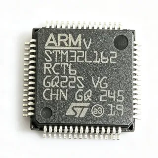
STM32L452RET6 - Ultra-Low-Power ARM Cortex-M4 MCU | STMicroelectronics
MPN: STM32L452RET6 ✓ Active| Qty | Unit Price | Extended |
|---|---|---|
| 1 | $8.5 | $8.50 |
| 10 | $7.65 | $76.50 |
| 100 | $6.8 | $680.00 |
| 500 | $6.12 | $3,060.00 |
| 1,000 | $5.5 | $5,500.00 |
STM32L452RET6 Overview
What is an ARM Cortex-M4 microcontroller? It is a 32-bit processor core designed for embedded systems, offering a balance of performance, power efficiency, and rich peripheral integration. The Cortex-M4 includes a floating-point unit (FPU) and DSP instructions, enabling efficient handling of complex mathematical operations. In the system hierarchy, a microcontroller (MCU) is a complete computer-on-a-chip, integrating CPU, memory, and peripherals, and is a subset of embedded processors, which are part of the broader semiconductor category. The STM32L4 series specifically targets low-power applications, extending battery life in portable and IoT devices.
Key features of the STM32L452RET6 include its ultra-low-power modes (Sleep, Low-power run, Low-power sleep, Stop 0/1/2, Standby, and Shutdown), with current consumption as low as 28 µA in Stop 2 mode with RTC and 112 nA in Shutdown mode. It also features a 12-bit ADC with hardware oversampling, a 12-bit DAC, two comparators, and an operational amplifier. The device supports a wide supply voltage range of 1.71 V to 3.6 V, making it suitable for battery-powered designs. It also includes a true random number generator (TRNG), a CRC calculation unit, and a 96-bit unique ID.
Technically, the STM32L452RET6 is built on a 40 nm process technology, enabling its low power consumption. It includes an advanced memory protection unit (MPU) and a secure access mode for enhanced security. The device supports external memory interfaces via FSMC for SRAM, PSRAM, NOR, and NAND memories. It also features a flexible power controller that allows dynamic voltage scaling to optimize power consumption based on processing load.
Typical applications include industrial sensors, smart meters, healthcare devices, wearable electronics, and IoT endpoints. Its combination of low power, high performance, and rich analog peripherals makes it suitable for applications requiring precise analog measurements and long battery life. For example, in a smart meter, the STM32L452RET6 can handle metrology calculations while maintaining low power consumption for battery operation.
When designing with this device, consider using the low-power modes effectively to maximize battery life. The Stop 2 mode with RTC is ideal for periodic wake-up applications. Also, ensure proper decoupling of the power supply pins and use the internal voltage regulator for optimal performance. The device supports a wide range of development tools, including STM32CubeMX and STM32CubeIDE, which simplify configuration and code generation.
Drop-in alternatives for STM32L452RET6 — same package, pin-to-pin compatible. Different-package parts requiring PCB rework are excluded.
Variants in this series
Same-series models that are drop-in compatible with STM32L452RET6 (same form factor and footprint) — differing in Core, Flash Memory, Package, SRAM.
Quick Comparison Tool — Select alternative parts for side-by-side comparison:
STM32L452RET7
✅ Drop-In ⚠️ Specs Unverified📋 Reference alternative (not in catalog)
STM32L452RCT6
✅ Drop-In ⚠️ Specs Unverified📋 Reference alternative (not in catalog)
STM32L452RGT6
✅ Drop-In ⚠️ Specs Unverified📋 Reference alternative (not in catalog)
STM32L452RCT7
✅ Drop-In ⚠️ Specs Unverified📋 Reference alternative (not in catalog)
STM32L452RGT7
✅ Drop-In ⚠️ Specs Unverified📋 Reference alternative (not in catalog)
STM32L452RET6TR
✅ Drop-In ⚠️ Specs Unverified📋 Reference alternative (not in catalog)
STM32L452RET6
✅ Drop-In ⚠️ Specs Unverified✓ In Stock
$5.5 / Unit
View Datasheet →STM32L452RET6 Maximum Ratings & Electrical Characteristics
| Core | ARM Cortex-M4 with FPU |
| Max Clock Frequency | 80 MHz |
| Flash Memory | 512 KB |
| SRAM | 160 KB |
| Supply Voltage Range | 1.71 V to 3.6 V |
| Operating Temperature Range | -40°C to +85°C |
| Package | LQFP-64 |
| Mounting Type | Surface Mount |
| Number of I/Os | 51 |
| ADC Resolution | 12-bit |
| DAC Resolution | 12-bit |
| Communication Interfaces | USART, SPI, I2C, USB 2.0 FS, SAI, CAN |
| Low Power Mode Current (Stop 2) | 28 µA (typ) with RTC |
| Low Power Mode Current (Shutdown) | 112 nA (typ) |
| RoHS Status | Compliant |
STM32L452RET6 Pin Configuration
| Pin 1 | VBAT — Backup battery supply |
| Pin 2 | PC13 — GPIO / RTC tamper |
| Pin 3 | PC14 — GPIO / OSC32_IN |
| Pin 4 | PC15 — GPIO / OSC32_OUT |
| Pin 5 | PF0 — GPIO / OSC_IN |
| Pin 6 | PF1 — GPIO / OSC_OUT |
| Pin 7 | NRST — Reset |
| Pin 8 | VDD — Digital power supply |
| Pin 9 | VSS — Ground |
| Pin 10 | VDDA — Analog power supply |
| Pin 11 | PA0 — GPIO / ADC_IN0 |
| Pin 12 | PA1 — GPIO / ADC_IN1 |
| Pin 13 | PA2 — GPIO / USART2_TX |
| Pin 14 | PA3 — GPIO / USART2_RX |
| Pin 15 | PA4 — GPIO / DAC_OUT1 |
| Pin 16 | PA5 — GPIO / DAC_OUT2 |
| Pin 17 | PA6 — GPIO / SPI1_MISO |
| Pin 18 | PA7 — GPIO / SPI1_MOSI |
| Pin 19 | PB0 — GPIO / ADC_IN8 |
| Pin 20 | PB1 — GPIO / ADC_IN9 |
| Pin 21 | PB2 — GPIO / BOOT1 |
| Pin 22 | PB10 — GPIO / I2C2_SCL |
| Pin 23 | PB11 — GPIO / I2C2_SDA |
| Pin 24 | PB12 — GPIO / SPI2_NSS |
| Pin 25 | PB13 — GPIO / SPI2_SCK |
| Pin 26 | PB14 — GPIO / SPI2_MISO |
| Pin 27 | PB15 — GPIO / SPI2_MOSI |
| Pin 28 | PC6 — GPIO / USART6_TX |
| Pin 29 | PC7 — GPIO / USART6_RX |
| Pin 30 | PC8 — GPIO / USART6_CK |
| Pin 31 | PC9 — GPIO / I2C3_SDA |
| Pin 32 | PA8 — GPIO / USB_OTG_FS_SOF |
| Pin 33 | PA9 — GPIO / USB_OTG_FS_VBUS |
| Pin 34 | PA10 — GPIO / USB_OTG_FS_ID |
| Pin 35 | PA11 — GPIO / USB_OTG_FS_DM |
| Pin 36 | PA12 — GPIO / USB_OTG_FS_DP |
| Pin 37 | PA13 — GPIO / SWDIO |
| Pin 38 | PA14 — GPIO / SWCLK |
| Pin 39 | PA15 — GPIO / JTDI |
| Pin 40 | PB3 — GPIO / JTDO |
| Pin 41 | PB4 — GPIO / NJTRST |
| Pin 42 | PB5 — GPIO / I2C1_SMBA |
| Pin 43 | PB6 — GPIO / I2C1_SCL |
| Pin 44 | PB7 — GPIO / I2C1_SDA |
| Pin 45 | BOOT0 — Boot mode selection |
| Pin 46 | PB8 — GPIO / CAN_RX |
| Pin 47 | PB9 — GPIO / CAN_TX |
| Pin 48 | VDD — Digital power supply |
| Pin 49 | VSS — Ground |
| Pin 50 | PC0 — GPIO / ADC_IN10 |
| Pin 51 | PC1 — GPIO / ADC_IN11 |
| Pin 52 | PC2 — GPIO / ADC_IN12 |
| Pin 53 | PC3 — GPIO / ADC_IN13 |
| Pin 54 | PC4 — GPIO / ADC_IN14 |
| Pin 55 | PC5 — GPIO / ADC_IN15 |
| Pin 56 | PD2 — GPIO / USART5_TX |
| Pin 57 | PE7 — GPIO / FSMC_D4 |
| Pin 58 | PE8 — GPIO / FSMC_D5 |
| Pin 59 | PE9 — GPIO / FSMC_D6 |
| Pin 60 | PE10 — GPIO / FSMC_D7 |
| Pin 61 | PE11 — GPIO / FSMC_D8 |
| Pin 62 | PE12 — GPIO / FSMC_D9 |
| Pin 63 | PE13 — GPIO / FSMC_D10 |
| Pin 64 | PE14 — GPIO / FSMC_D11 |
Typical Applications
STM32L452RET6 is suitable for 6 applications: Industrial Sensors, Smart Meters, Healthcare Devices, IoT Endpoints, Wearable Electronics, Test and Measurement.
Industrial Sensors
The STM32L452RET6 is ideal for industrial sensors due to its ultra-low-power modes and high-performance Cortex-M4 core. It can process sensor data with its 12-bit ADC and communicate via multiple interfaces. In a typical industrial sensor node, the MCU reads analog signals from temperature, pressure, or flow sensors, performs signal conditioning, and transmits data over RS-485 or CAN. The low-power Stop 2 mode (28 µA) allows battery-powered operation for years. The 80 MHz core ensures real-time processing of sensor data, while the FPU accelerates floating-point calculations for calibration algorithms. Designers can use the STM32CubeMX to configure peripherals and generate code, reducing development time.
Recommended
Smart Meters
Smart meters require precise measurement and low power consumption. The STM32L452RET6's 12-bit ADC with hardware oversampling enables accurate energy metering. Its low-power modes allow the meter to run on battery for extended periods. The MCU can handle metrology calculations, display updates, and communication with the grid. The 512 KB Flash provides ample space for firmware and calibration data. The device's wide supply voltage range (1.71 V to 3.6 V) accommodates battery voltage variations. The STM32L452RET6 also supports multiple communication protocols (e.g., PLC, RF) via its USART and SPI interfaces, making it a versatile choice for smart metering applications.
Recommended
Healthcare Devices
In healthcare devices like wearable monitors, the STM32L452RET6 offers a balance of performance and power efficiency. Its low-power modes extend battery life, while the FPU handles complex signal processing for ECG or PPG signals. The device's analog peripherals (ADC, DAC, op-amp) enable direct sensor interfacing. The 160 KB SRAM supports real-time data buffering. The MCU's security features, including a true random number generator, help protect patient data. The STM32L452RET6 can operate from a coin cell battery, making it suitable for compact wearable designs. Its wide operating temperature range ensures reliable operation in various environments.
Recommended
IoT Endpoints
The STM32L452RET6 is a popular choice for IoT endpoints due to its ultra-low-power consumption and rich connectivity options. It can run on batteries for years, waking up periodically to send sensor data over LoRa, BLE, or Wi-Fi. The MCU's multiple low-power modes allow fine-grained power management. The 512 KB Flash is sufficient for complex IoT protocols and over-the-air updates. The device's security features, including a unique ID and CRC, enhance device authentication. The STM32L452RET6 supports FreeRTOS and various middleware, simplifying IoT application development. Its small LQFP-64 package is suitable for space-constrained designs.
Recommended
Wearable Electronics
Wearable devices demand ultra-low power and small form factor. The STM32L452RET6's Shutdown mode (112 nA) is ideal for standby operation. Its Cortex-M4 core provides enough processing power for activity tracking algorithms. The device's analog peripherals enable direct connection to accelerometers and heart rate sensors. The 160 KB SRAM supports data logging. The MCU can operate from a small Li-Po battery, and its wide voltage range ensures stable operation as the battery discharges. The STM32L452RET6 also supports USB for charging and data transfer. Its low-power modes allow the device to last for days on a single charge.
Recommended
Test and Measurement
The STM32L452RET6 is suitable for portable test and measurement equipment due to its high-resolution ADC and low power consumption. It can be used in handheld multimeters, data loggers, and signal analyzers. The 12-bit ADC with oversampling provides accurate measurements. The device's multiple timers and PWM outputs enable waveform generation. The 512 KB Flash allows for complex measurement algorithms. The MCU's USB interface enables easy connection to a PC for data analysis. Its low-power modes extend battery life in field use. The STM32L452RET6's rich peripheral set makes it a versatile choice for various test instruments.
Recommended
Recommended Products Summary
Engineering reference data for STM32L452RET6 — comparison, design guidance, and compliance information.
Selection Guide
Comparison with Alternatives
| Parameter | This Product | STM32L452RET7 | STM32L452RCT6 | STM32L452RGT6 |
|---|---|---|---|---|
| Package | LQFP-64 | LQFP-64 | LQFP-64 | LQFP-64 |
| Brand | STMicroelectronics | STMicroelectronics | STMicroelectronics | STMicroelectronics |
| Core | ARM Cortex-M4 with FPU | ARM Cortex-M4 with FPU | ARM Cortex-M4 with FPU | ARM Cortex-M4 with FPU |
| Max Clock Frequency | 80 MHz | 80 MHz | 80 MHz | 80 MHz |
| Flash Memory | 512 KB | 512 KB | 256 KB | 1 MB |
| SRAM | 160 KB | 160 KB | 64 KB | 320 KB |
| Supply Voltage Range | 1.71 V to 3.6 V | 1.71 V to 3.6 V | 1.71 V to 3.6 V | 1.71 V to 3.6 V |
| Operating Temperature Range | -40°C to +85°C | -40°C to +125°C | -40°C to +85°C | -40°C to +85°C |
Key Differentiators
- Ultra-low-power consumption with 28 µA in Stop 2 mode (vs STM32L452RCT6)
- 512 KB Flash and 160 KB SRAM (vs STM32L452RCT6)
- Extended temperature range option (RET7) (vs STM32L452RET6)
Design Notes
The STM32L452RET6 supports a wide supply voltage range of 1.71 V to 3.6 V. For optimal power consumption, use the internal voltage regulator in low-power mode. Decouple all VDD and VDDA pins with 100 nF capacitors, and place a 4.7 µF capacitor on the main VDD rail. In battery-powered designs, use the low-power modes (Stop 2, Shutdown) to extend battery life. The VBAT pin should be connected to a backup battery or tied to VDD if not used.
For the LQFP-64 package, ensure proper grounding and decoupling. Place decoupling capacitors close to the power pins. Use a solid ground plane to minimize noise. For the ADC, separate analog and digital grounds to reduce noise. The STM32L452RET6 has an exposed pad (EP) on the bottom of the package; solder it to the PCB ground plane for thermal and electrical performance.
When using the low-power modes, ensure that the RTC and backup registers are properly configured. The VBAT pin must be connected to a valid supply to retain RTC functionality. Also, be aware that the BOOT0 pin must be tied to a defined level to avoid accidental boot mode changes. For programming, use the SWD interface (PA13/PA14) and ensure the reset pin is not held low.
Compliance Information
RoHS compliant per STMicroelectronics product page. Not AEC-Q100 qualified - this is a general-purpose MCU, not automotive grade.