محصولات (46,000+)

HT66F25D - A/D Flash 8-bit MCU with EEPROM | Holtek
HT66F25D

HT66F25D - A/D Flash 8-bit MCU with EEPROM | Holtek

The Holtek HT66F25D is an A/D Flash type 8-bit MCU with EEPROM, built on a high-performance RISC architecture, supplied in an SOP small-outline package. It belongs to Holtek's enhanced Flash MCU family that integrates an analog-to-digital converter, non-volatile EEPROM data memory, and a high-current LED driver output structure on a single chip, allowing multi-programming convenience thanks to its Flash program memory. An 8-bit Flash microcontroller is a complete computing system on a single integrated circuit: it combines a processor core, program Flash memory, data RAM, EEPROM, peripheral functions such as timers, PWM and ADC channels, and general-purpose I/O. Within the semiconductor hierarchy, the HT66F25D sits in the microcontroller -> embedded processor -> integrated circuit taxonomy, positioned for cost-sensitive embedded control where on-chip analog input and small non-volatile data storage remove the need for external components. Key differentiating features of this device, as stated by Holtek and the datasheet aggregators carrying the official document, include the Flash program memory with multi-programming support (enabling in-circuit update during development and production), the integrated A/D converter for reading analog sensors directly, the on-chip EEPROM for calibration data and user settings that must survive power cycles, and the enhanced high-current LED driver capability highlighted in Holtek's product notification for the HT66F24D/HT66F25D family. Architecturally, the device follows Holtek's RISC-style 8-bit core used across the HT66Fx1D series, with register-mapped I/O ports (PA, PB, PC with individual pull-up and wake-up control bits per the datasheet register lists), typical of the family's low-cost, low-pin-count embedded control philosophy. The exact clock frequency range, ADC resolution, Flash and RAM capacities are detailed in the 175-page official datasheet and should be confirmed there for each specific suffix. Typical applications include small appliance control, LED lighting and brightness control exploiting the high-current driver outputs, battery chargers, sensor interfaces using the A/D converter, and consumer products requiring configuration storage in EEPROM. A key design consideration: this device has been formally phased out by Holtek. According to the official Holtek EOL notification PDF, the last time buy date was April 14, 2026, so new designs must qualify a replacement immediately. This page synthesizes distributor sourcing data, the official Holtek EOL cross-reference notice, and drop-in replacement analysis not found on standard datasheet aggregator sites.

RFQ تماس
HT66FB550 - 8-bit USB Flash MCU, 8KB, LQFP-48 | Holtek
HT66FB550

HT66FB550 - 8-bit USB Flash MCU, 8KB, LQFP-48 | Holtek

The Holtek Semiconductor HT66FB550 is an 8-bit Flash A/D USB microcontroller with a 12-bit ADC, 8KB of Flash program memory, 37 general-purpose I/O lines, an SPI interface, and USB 2.0 Full Speed connectivity, housed in a 48-pin LQFP (7x7 mm) package. An 8-bit microcontroller unit (MCU) is a single-chip computer that integrates a processor core, memory, and peripherals on one die, sitting within the broader hierarchy of semiconductor devices as: microcontroller -> embedded processor -> integrated circuit. The HT66FB550 belongs to Holtek's A/D Flash USB series, which combines Holtek's high-performance RISC core with direct analog signal interfacing and a USB interface, eliminating the need for a separate USB transceiver chip in many designs. Key features include the USB 2.0 Full Speed device controller (12 Mbps), a 12-bit resolution analog-to-digital converter, 8KB of Flash program memory, an SPI serial interface, and a wide operating voltage range of 2.2V to 5.5V. These specifications make the device well suited to cost-sensitive designs that must digitize analog sensor signals and stream them over USB without a discrete USB bridge. Technically, the HT66FB550 uses Holtek's 8-bit high-performance RISC architecture, common to the HT66FB540, HT66FB550, and HT66FB560 family members, which differ mainly in memory density and pin count. The integrated USB serial interface engine (SIE) handles protocol framing in hardware, reducing firmware overhead and CPU loading compared with bit-banged USB implementations. Typical applications include USB HID devices such as game controllers and keyboards, USB sensor data loggers, battery chargers with USB telemetry, test fixtures, and industrial control panels that interface directly to analog transducers through the 12-bit ADC. When designing with this device, respect the 2.2V to 5.5V supply range and place 0.1uF decoupling capacitors at each VDD pin; the USB full-speed line requires 22-ohm series resistors and careful 90-ohm differential routing on the DP/DM pair. This page synthesizes distributor pricing, drop-in family alternatives, application guidance, and design notes not found in the manufacturer datasheet, offering engineering value beyond a raw specification listing.

RFQ تماس
ICE40HX4K-TQ144 - 3520-LUT 1.2V FPGA | Lattice Semiconductor
ICE40HX4K-TQ144

ICE40HX4K-TQ144 - 3520-LUT 1.2V FPGA | Lattice Semiconductor

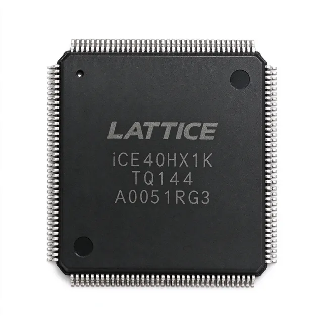
The Lattice Semiconductor ICE40HX4K-TQ144 is an ultra-low-power HX-series field-programmable gate array (FPGA) with 3,520 logic cells, 107 I/Os, 81,920 bits of configuration memory, and a 144-pin TQFP package. It operates from a 1.2 V core supply according to the supplied distributor data. The device targets compact, low-power programmable logic systems where FPGA flexibility is needed without the power and board complexity of a larger high-performance FPGA. A field-programmable gate array is a configurable digital semiconductor that contains programmable logic blocks, routing resources, input/output blocks, and configuration memory. In the hierarchy, an FPGA is a programmable logic device, a digital IC, and a semiconductor. Unlike a fixed-function microcontroller or application-specific integrated circuit, an FPGA can be programmed after manufacture to implement parallel data paths, control logic, serial interfaces, and hardware signal processing. The ICE40HX4K provides 3,520 logic cells and 81,920 bits of configuration memory, as identified by DigiKey and Mouser search results. Its 107 I/Os provide substantial connectivity for external memory, sensors, communications, control signals, and general-purpose digital interfaces. The HX family is positioned by Lattice as a low-power, high-performance FPGA family, making the part suitable for embedded control, communication, instrumentation, and education platforms where low static power and fast programmable logic are important. The 144-pin TQFP package exposes the FPGA in a conventional surface-mount form factor suitable for automated assembly and multilayer PCB designs. The verified source snippets identify the package as 144-pin TQFP or 144-LQFP terminology; designers should confirm the exact mechanical drawing and pin names against the manufacturer datasheet before releasing a PCB footprint. The supplied data does not specify speed grade, temperature range, power consumption, pin names, memory architecture beyond configuration capacity, or I/O voltage limits. Typical uses include custom interface controllers, low-power sensor aggregation, digital signal conditioning, communications adapters, test fixtures, and FPGA-based education or prototyping boards. For a new design, use the manufacturer’s configuration toolchain and verify pin assignments, supported I/O standards, clocking resources, power rails, decoupling requirements, and programming interface compatibility. Because the supplied evidence confirms the family and capacity but not a complete electrical characterization, unsupported values should not be inferred from generic iCE40 family claims.

USD $10.66 موجود در انبار
ICL7106CJL - 3.5-Digit LCD ADC | Analog Devices
ICL7106CJL

ICL7106CJL - 3.5-Digit LCD ADC | Analog Devices

The Analog Devices ICL7106CJL is a production 3.5-digit successive-approximation analog-to-digital converter with direct LCD display drivers, supplied in a 40-pin ceramic dual-inline package. It combines a multiplexed seven-segment LCD output with an integrated analog measurement system designed for panel meters, laboratory instruments, and industrial transducers. The original device family was also associated with Harris, Intersil, and Maxim Integrated, while the current manufacturer product page identifies the ICL7106 as a production part. An integrated data converter is a mixed-signal semiconductor that converts an analog input voltage into a numeric representation. In the ICL7106, the converter and LCD-driving functions are combined to reduce the number of external components required for a digital panel display. Analog Devices describes the device family as a 3.5-digit A/D converter with direct LCD drivers, allowing the measured result to be displayed without a separate display-driver IC in conventional applications. The converter's defining application feature is its direct seven-segment LCD drive capability. The measured count is represented as a three-digit display plus sign or other status information, depending on the external circuit configuration. The 40-pin CDIP construction also provides ample connection count for analog inputs, references, oscillator components, display outputs, and control functions described in the manufacturer documentation. The ICL7106 family uses a dual-slope conversion technique, which is useful when rejecting interference at frequencies related to the integration period. Analog Devices states that dual-slope conversion automatically rejects interference signals common in industrial environments. The same product overview identifies true differential input and reference capability as useful for ratiometric measurements involving ohms, resistive bridges, and bridge transducers. Typical uses include digital panel meters, laboratory meters, process-control displays, temperature indicators, weighing systems, and other equipment that must measure an analog quantity and present it locally on an LCD. A panel-meter design can place the ICL7106 close to the sensor interface, route the analog input and reference through short paths, and connect the display directly to the converter's LCD outputs. When laying out an ICL7106CJL circuit, follow the pin-description and typical-application diagrams in the manufacturer datasheet for input filtering, reference routing, oscillator components, and LCD connections. Keep sensitive analog and reference nets away from display outputs and switching nodes. Because the CDIP package is through-hole, its long leads make hand insertion straightforward, but production designs must still account for lead spacing, board cleanliness, and mechanical strain. This product record combines the manufacturer overview, distributor identification of the 40-CDIP package, lifecycle information, and cross-reference findings for ICL7106CJL. It also distinguishes directly documented characteristics from fields that require confirmation against the datasheet, helping engineers plan replacement sourcing without relying on unverified electrical assumptions.

RFQ تماس
ICL7106CM44 - 3.5-Digit LCD A/D Converter | Renesas
ICL7106CM44

ICL7106CM44 - 3.5-Digit LCD A/D Converter | Renesas

Renesas Electronics ICL7106CM44 is a 3.5-digit low-power A/D converter with integrated seven-segment decoding and LCD display drivers in a 44-pin MQFP package measuring 10 x 10 mm. The device combines an analog-to-digital converter, reference, clock, counter logic, seven-segment decoder, and multiplexed liquid-crystal display driver in one package. An A/D converter such as the ICL7106CM44 converts an analog input voltage into a digital measurement suitable for instrumentation, panel meters, and laboratory equipment. The ICL7106 series belongs to the signal-conversion hierarchy: analog-to-digital converter, digital meter converter, display-oriented integrated circuit, and ultimately a mixed-signal semiconductor. Its integrated display interface is especially useful when a readable numeric result is required without adding a separate display decoder. The principal device characteristics include 3.5-digit resolution, low-power operation, seven-segment decoding, integrated display driving, a reference, and a clock. The ICL7106 is designed for multiplexed LCD displays and includes backplane drive capability. These features reduce the number of external components required in digital panel-meter and process-measurement equipment while keeping the measurement and display functions together. Technically, the ICL7106 family integrates the signal-conditioning and conversion path with counting and display functions. Differential input capability is useful for rejecting common-mode voltage in measurement systems, while the internal reference supports a repeatable conversion baseline. The converter's internal oscillator and system clock organization make it suitable for autonomous measurement panels that do not require an external microprocessor simply to produce a display reading. Typical applications include digital panel meters, laboratory measurement instruments, process-monitoring displays, weighing scales, industrial sensor interfaces, and standalone test equipment. The LCD-oriented ICL7106 is particularly appropriate where a compact numeric readout is preferred over direct LED excitation. System designers should select the display and external component configuration by following the manufacturer datasheet's typical application circuit. A critical design consideration is display compatibility: the ICL7106 provides multiplexed LCD drive, whereas the closely related ICL7107 targets LED displays. Do not substitute an LED-display version without verifying every display connection, pin function, electrical limit, and board footprint. Use the pin-description table and application circuit in the manufacturer datasheet when assigning PCB tracks. This product analysis combines the verified package, resolution, display, and functional characteristics with practical guidance for selecting the correct A/D converter and designing a reliable digital measurement instrument.

RFQ تماس
ICL7106CPL+ - 3.5-Digit LCD ADC | Analog Devices
ICL7106CPL+

ICL7106CPL+ - 3.5-Digit LCD ADC | Analog Devices

Analog Devices ICL7106CPL+ is a low-power, 3.5-digit monolithic analog-to-digital converter with a 40-pin PDIP package. It integrates a seven-segment decoder, LCD display driver, voltage reference, and clock circuit, allowing a measurement system to display the converted result without external display-drive circuitry. The verified product information identifies the converter as a high-performance, low-power device intended for liquid-crystal display instruments. An A/D converter transforms an analog input voltage into a numeric representation. The ICL7106 integrates the functions needed for a basic digital panel meter: input conditioning, conversion, seven-segment decoding, polarity indication, display drivers, an internal reference, and an oscillator. In the electronic-component hierarchy, it is an ADC, a data-conversion IC, and a mixed-signal instrument integrated circuit. It differs from the ICL7107 because the ICL7106 includes multiplexed backplane drive for an LCD rather than direct drive for a larger LED display. The verified sources describe the ICL7106 as a high-performance, low-power 3.5-digit converter with very high input impedance. On-chip active components include polarity and digit drivers, segment decoders, a voltage reference, and a clock circuit. These integrated functions reduce the number of external components required in a panel-meter design while providing a direct interface to a nonmultiplexed liquid-crystal display. The C designation and PL package identify a temperature-grade and packaging arrangement within the ICL7106 product family, while the trailing plus denotes the lead-free ordering code used by current distributor records. The device is supplied in a 40-pin PDIP package identified by distributor listings as 40-PDIP or 40-DIP. The manufacturer product page lists the ICL7106 as a production 3.5-digit A/D converter and provides its family documentation. Typical uses include digital panel meters, laboratory instruments, temperature indicators, process-monitoring displays, weighing scales, and other instruments that measure an analog voltage and present the result on a seven-segment LCD. Because the converter includes the display decoder and driver, it is especially useful where a compact instrument display is required without building a separate display interface. The principal design consideration is to follow the manufacturer's recommended input, reference, clock, display, and bypass connections. Because the exact pin names, input limits, conversion timing, reference characteristics, and electrical ratings are not included in the supplied excerpts, engineers should verify those values and the complete pinout in the manufacturer datasheet before final PCB or firmware design. This product page consolidates current distributor availability, verified pricing, source links, package information, replacement context, and practical design considerations. It distinguishes the ICL7106's LCD-focused role from the LED-oriented ICL7107 and makes missing technical data explicit rather than estimating values that are not supported by the retrieved sources.

RFQ تماس
ICL7106CPL+3 - 3.5-Digit LCD ADC | Analog Devices
ICL7106CPL+3

ICL7106CPL+3 - 3.5-Digit LCD ADC | Analog Devices

The Analog Devices ICL7106CPL+3 is a monolithic 3.5-digit successive-approximation-style display A/D converter and direct LCD driver in a 40-pin PDIP package. It combines a 3.5-digit measurement range, seven-segment decoding, LCD segment and polarity drive, an internal voltage reference, and an internal clock in one low-power IC. The device directly drives non-multiplexed liquid-crystal displays without requiring separate display-drive circuitry. An integrated A/D converter such as the ICL7106CPL+3 converts an analog input voltage into a digital code suitable for direct panel display. Within the ADC and data-acquisition hierarchy, it is a display-oriented integrating converter rather than a high-speed sampled ADC. Its true-differential input and reference arrangement support ratiometric measurements of resistance, resistance bridges, and other transducers where excitation drift and reference variation can be canceled. The principal feature is integrated display control. The ICL7106CPL+3 includes seven-segment decoders, digit drivers, segment drivers, polarity drive, a voltage reference, and a clock circuit. This integration removes the need for external display multiplexers or driver ICs. The 3.5-digit resolution supports panel readings from 000 to 999 plus overrange indication, while the 40-pin PDIP package provides through-hole compatibility for laboratory, panel-meter, and industrial instrumentation designs. The conversion system uses dual-slope integration, as identified in the ICL7106 documentation. Dual-slope operation averages the unknown input over a defined integration interval and compares the result with a reference, reducing sensitivity to periodic interference when the measurement is synchronized appropriately. The converter also includes a zero-integrator phase that eliminates overrange hangover and hysteresis effects identified by Analog Devices. Typical uses include digital panel meters, laboratory meters, temperature indicators, weighing displays, resistance-measurement instruments, and ratiometric bridge or transducer readouts. The device is especially useful where the measured value must appear directly on a non-multiplexed LCD and where a complete display subsystem is required without adding a separate microcontroller and display driver. When designing the circuit, follow the manufacturer's input, reference, clock, power, and LCD connection guidance exactly. Preserve the specified input impedance and reference arrangement, route sensitive analog and reference nets away from display drive traces, and account for LCD segment capacitance when selecting timing and PCB routing. Verify that the selected display uses the expected segment and polarity drive arrangement. This page combines manufacturer product information, cross-reference findings, application guidance, and engineering-focused selection criteria. It highlights where ICL7106CPL+3 is appropriate, how its integrated LCD-driver architecture reduces external circuitry, and which documented alternatives share the 40-pin PDIP footprint for replacement planning.

RFQ تماس
ICL7106CQH-D - 3.5-Digit LCD ADC | Analog Devices
ICL7106CQH-D

ICL7106CQH-D - 3.5-Digit LCD ADC | Analog Devices

Analog Devices ICL7106CQH-D is a 3.5-digit successive-approximation-style display converter designed for low-power digital panel-meter and measurement applications. The device is identified as a 3.5-digit display driver with LCD output, dual-slope conversion, true differential input and reference inputs, and a 44-pin PLCC J-lead package measuring 16.59 mm by 16.59 mm. It is intended for instrumentation where a stable digital measurement must be displayed directly on an LCD. The ICL7106 is a low-power analog-to-digital converter with integrated LCD display-drive capability. In a typical measurement chain, an analog sensor signal is conditioned, applied between the differential input terminals, and referenced against the internal or external reference arrangement. The converter then produces a three-and-a-half-digit result for direct display, reducing the need for a separate display controller. Its differential input and reference architecture supports ratiometric measurements involving resistive sensors and bridge transducers. Key characteristics include 3.5-digit resolution, LCD display-driver output, dual-slope conversion, one analog input channel, and J-lead termination in a 44-PLCC package. The ICL7106 family also includes the ICL7107, which is electrically related but intended for LED-display rather than LCD-display designs. The zero-integrator phase introduced for the ICL7106 and ICL7107 reduces overrange hangover and hysteresis effects, helping the converter return predictably to the normal conversion cycle after an overload condition. The ICL7106CQH-D is commonly used in digital panel meters, handheld meters, laboratory instruments, weighing equipment, temperature measurement, pressure measurement, and other systems that need a local numerical LCD readout. The commercial temperature grade and 44-pin surface-mount PLCC package make it appropriate for compact industrial and instrument designs where a traditional DIP implementation would be too large. Designers should preserve the reference and input signal paths for low error, provide suitable bypassing close to the supply pins, and follow the manufacturer’s external-component recommendations. The reference arrangement directly affects full-scale conversion accuracy, while the input network must keep leakage, noise, and source resistance within the limits of the selected integration and reference scheme. This page combines manufacturer product information, distributor availability and pricing context, package details, replacement guidance, and practical application notes. It is intended to help engineers identify the correct ICL7106 variant, distinguish LCD from LED display versions, and plan a board-level implementation using the 44-PLCC footprint.

RFQ تماس
ICL7106EJL - 3.5-Digit LCD A/D Converter | Maxim Integrated
ICL7106EJL

ICL7106EJL - 3.5-Digit LCD A/D Converter | Maxim Integrated

The Maxim Integrated ICL7106EJL is a low-power, 3.5-digit successive-approximation analog-to-digital converter designed for direct liquid-crystal display interfacing. The device operates from a 15 V supply and is packaged in a 40-pin ceramic dual-inline package, designated CDIP-40. Its integrated signal-conditioning and display features make it suitable for standalone digital instrumentation, panel meters, laboratory equipment, and precision weighing systems. An A/D converter is an interface integrated circuit that converts an analog voltage into a digital value for measurement, display, control, or data processing. The ICL7106EJL belongs to the specialized ADC and DAC product family, combining a 3.5-digit conversion engine, seven-segment decoder, display driver, reference source, clock, and digital filtering. Unlike a general-purpose ADC requiring an external display controller, it is optimized for multiplexed LCD glass. The ICL7106 uses differential input architecture, allowing a measurement amplifier and reference arrangement to reject common-mode voltage. Its integrated reference source simplifies standalone designs, while digital filtering helps stabilize displayed results. The EJL ordering code identifies the 15 V, extended-temperature and CDIP-40 variant associated with this product designation. Typical applications include digital panel meters, laboratory measurement instruments, process-monitoring equipment, temperature controllers, and portable instrumentation. When implementing a circuit, evaluate input overdrive, reference accuracy, LCD segment drive requirements, and the relationship between integration time, noise performance, and conversion speed. The ceramic package also requires attention to thermal dissipation and mechanical handling during soldering and assembly. This product page combines the manufacturer device description with practical application guidance, pin-package information, design considerations, and sourcing support. For current pricing, inventory, lead time, and delivery options, use the Request a Quote form on this page rather than relying on historical distributor figures.

RFQ تماس
ICL7106EPL+ - 3.5-Digit LCD ADC | Maxim Integrated
ICL7106EPL+

ICL7106EPL+ - 3.5-Digit LCD ADC | Maxim Integrated

The Maxim Integrated ICL7106EPL+ is a monolithic 3.5-digit analog-to-digital converter designed to measure low-frequency differential or single-ended inputs and drive a nonmultiplexed liquid-crystal display. It integrates a voltage reference, clock circuit, polarity and digit drivers, segment decoders, and the functions required for direct LCD operation. The device is packaged as a 40-pin PDIP, with industrial-temperature ordering indicated by the E suffix. The + suffix identifies the manufacturer's lead-free product designation. The ICL7106 family is intended for instrumentation applications where a dedicated display, digital measurement, and relatively low power are more important than high conversion speed. An analog-to-digital converter, or ADC, converts a continuously varying analog voltage into a numeric value. A 3.5-digit integrating ADC such as the ICL7106 uses an integrating measurement approach and includes display decoding and drive circuitry, reducing the external component count required for a standalone panel meter. The ICL7106 differs from the related ICL7107 by driving a nonmultiplexed LCD, while the ICL7107 is intended for LED-display applications. This distinction makes display type an essential PCB and firmware-independent hardware selection criterion. The principal system-level benefits are integration and measurement simplicity. A high-input-impedance measurement front end allows the converter to work with sensor and instrumentation circuits without adding a separate display driver. On-board segment decoders, polarity and digit drivers, a voltage reference, and a clock eliminate several discrete functions from the meter design. These characteristics are especially useful in standalone laboratory instruments, temperature controllers, weighing indicators, process monitors, and service equipment where the analog input must appear directly as a readable numerical measurement. Because the ICL7106 is intended for low-power measurement rather than high-speed waveform acquisition, system timing and input conditioning determine practical performance. The input network, reference arrangement, integration period, clock source, and bypass components should follow the manufacturer's application guidance. Decoupling must be placed close to the supply and reference pins, while the analog input path should avoid long traces and sources of leakage. The LCD interface and converter functions are integrated, but the display still requires the appropriate glass connections and suitable common and segment drive arrangement. Typical applications include digital panel meters, temperature measurement instruments, laboratory readouts, industrial process indicators, portable measurement equipment, and equipment with an integrated numeric display. In these systems, the ICL7106EPL+ serves as both the measurement engine and the LCD interface. Designers should confirm the input range, reference voltage, conversion timing, display configuration, and supply requirements against the manufacturer datasheet before finalizing the analog front end and printed-circuit-board layout. For PCB design, begin by assigning the 40-pin PDIP footprint and checking the manufacturer's pin-description table for analog inputs, reference connections, supply rails, ground pins, clock connections, and LCD outputs. Avoid routing LCD segment and digit lines next to high-impedance analog inputs. Place input and bypass capacitors close to their associated pins, provide a stable ground return, and keep the analog and display paths physically separated where the board area permits. This product page combines the manufacturer's family-level technical description, package and ordering information, related 40-pin device data, application engineering guidance, and a replacement-focused comparison. It is intended to help engineers determine whether the ICL7106EPL+ matches the required display technology, package, lifecycle requirement, and instrumentation architecture before committing the design to production.

RFQ تماس
ICL7106IP - 3.5-Digit LCD A/D Converter | Analog Devices
ICL7106IP

ICL7106IP - 3.5-Digit LCD A/D Converter | Analog Devices

The Analog Devices ICL7106IP is a low-power, 3.5-digit successive-approximation A/D converter with integrated seven-segment decoders, LCD display drivers, reference, and clock circuitry in a 40-pin PDIP package. The converter is designed for liquid-crystal displays and uses dual-slope conversion to provide stable measurements in instrument and industrial environments. An A/D converter is an analog-to-digital converter that transforms a continuously varying voltage or current-derived signal into a numeric representation. The ICL7106 belongs to the display-oriented A/D converter hierarchy, combining measurement conversion, display decoding, display drive, reference voltage, and timing functions in one device. Its integrated LCD backplane drive is intended to reduce the external circuitry required for panel instruments. Key features of the ICL7106 include 3.5-digit resolution, seven-segment display decoding, LCD display-driver capability, an integrated reference, an integrated clock, true differential input and reference support, and dual-slope conversion. The device family is designed to reject interference signals common in industrial environments, while ratiometric measurement support is useful for ohms and bridge-transducer applications. The ICL7106 uses dual-slope conversion rather than a high-speed successive-approximation architecture. This approach integrates an input over a fixed measurement interval and compares the resulting charge with a reference-derived ramp. The architecture is well suited to panel meters, digital scales, temperature indicators, and other systems where measurement rate is less important than stable displayed readings and straightforward system integration. Typical applications include digital panel meters, resistance measurement instruments, bridge-sensor instrumentation, industrial process displays, laboratory meters, weighing systems, and portable measurement equipment. The LCD-focused ICL7106 is generally preferable to LED-display converter variants when the design uses a multiplexed liquid-crystal panel. Designers should follow the manufacturer datasheet for the exact pin assignments, reference connections, clock requirements, display timing, and input common-mode limits. The 40-pin PDIP footprint also requires sufficient board space, careful decoupling, and routing that separates sensitive analog input and reference paths from display-drive and digital timing nodes. This page consolidates manufacturer information, distributor availability, pricing context, package identification, and design guidance for engineers evaluating the ICL7106IP in new or replacement LCD instrument designs.

RFQ تماس
ICL7106IPL 3.5-Digit LCD A/D Converter | Maxim
ICL7106IPL

ICL7106IPL 3.5-Digit LCD A/D Converter | Maxim

The Maxim ICL7106IPL is a low-power 3 1/2-digit analog-to-digital converter designed for direct liquid-crystal display interfacing. It integrates the converter, seven-segment decoders, display drivers, voltage reference, and clock circuitry in one device, reducing the external component count required for a standalone measurement instrument. The ICL7106 is associated with the Intersil ICL7106 and ICL7107 family of high-performance, low-power display A/D converters. An ADC converts an analog voltage into a digital numerical representation. In the ICL7106, the conversion result is intended for a multiplexed LCD rather than a directly driven LED instrument display. The integration of the display drivers and reference circuit makes the device suitable for digital panel meters, laboratory instruments, handheld meters, weighing systems, and other equipment where a stable numeric readout is required. The principal function of the ICL7106IPL is measurement conversion combined with display control. Its 3 1/2-digit format is designed for applications where a signed or otherwise bounded numerical range is sufficient. The device includes polarity and digit drivers, segment decoders, a voltage reference, and a clock circuit, allowing the measurement system to operate without separate display-driver circuitry. The ICL7106 architecture uses a successive integration conversion technique associated with this family of low-power metering ICs. This approach is suited to relatively slow measurements where low power, good linearity, and display integration are more important than high sampling rates. The converter’s high input impedance helps reduce loading of the signal source, while the integrated reference supports repeatable measurement results when paired with appropriate external input, reference, and display networks. The ICL7106 family is commonly associated with digital voltmeters, current meters, panel meters, laboratory measurement equipment, and embedded instrumentation. A typical design provides the analog input to the converter, uses external components to set the measurement range and reference, and connects the converter to a multiplexed LCD. The ICL7106 variant is particularly appropriate when the display is an LCD; ICL7107 is generally identified with LED-display applications. When designing a circuit around ICL7106IPL, verify the package pinout and display interface against the manufacturer datasheet before assigning PCB tracks. Input filtering, reference decoupling, display glass compatibility, and the external component values for range and timing determine practical measurement performance. Because the available manufacturer page confirms the family function but does not state the complete ICL7106IPL electrical limits in the retrieved material, check the current datasheet for operating voltage, conversion timing, input range, and absolute maximum ratings. This product page combines the confirmed ICL7106 family architecture, the available official product-page information, and clearly identified cross-reference candidates. The comparison and selection notes emphasize package and pin compatibility, while the application guidance focuses on practical use of a low-power 3 1/2-digit LCD measurement system.

RFQ تماس
ICL7107CDL - 3.5 Digit Display ADC | Harris | 40-SBDIP
ICL7107CDL

ICL7107CDL - 3.5 Digit Display ADC | Harris | 40-SBDIP

Harris Corporation ICL7107CDL is a 3.5-digit CMOS analog-to-digital converter designed for panel-meter and digital-display applications. The device combines a 40-pin SBDIP package with a 6 V supply indication and is specifically associated with LED display drivers. Its measurement architecture is intended to produce stable, readable results from low-level analog inputs while driving multiplexed seven-segment displays. An ADC such as the ICL7107CDL is a mixed-signal integrated circuit that converts an analog voltage into a numeric value. In the broader hierarchy, it belongs to data-converter ICs, analog-to-digital converters, and display-oriented measurement ICs. The ICL7107 family is commonly used where a panel meter, digital voltmeter, counter, or process-monitoring instrument needs to present an electrical measurement directly through a seven-segment display. The key application feature of the ICL7107CDL is its integrated 3.5-digit conversion and display-driver function. A 3.5-digit meter can display a full range of digits plus one sign or half-digit indication, making it suitable for positive or negative measurements. The 40-SBDIP through-hole package supports conventional PCB mounting, socket assembly, and repair or replacement of older instrument designs. The verified product listing identifies the device as a 40-SBDIP Harris Corporation part. The ICL7107CDL is associated with LED display drivers, which makes it appropriate for digital voltmeters, bench instruments, industrial panel meters, laboratory equipment, and embedded measurement panels. Its external connection requirements, reference voltage, input range, timing behavior, and display-drive characteristics must be confirmed against the manufacturer datasheet before a new PCB is laid out. The device should not be selected solely from its display-driver description because sensor excitation, reference accuracy, input filtering, and calibration determine the final measurement performance. For an instrument design, place the converter close enough to the analog input and reference network to minimize pickup on high-impedance nodes. Use a stable reference arrangement, appropriate input filtering, and decoupling near the supply pins. A conventional through-hole layout should preserve the manufacturer's pin numbering and provide adequate board spacing for the 40-pin SBDIP body. Verify the exact display-driver outputs and segment/common-anode or common-cathode requirements against the target display. This product page combines the Harris and Intersil documentation references, verified distributor identification, package information, application positioning, and engineering guidance. It distinguishes the ICL7107CDL from broader cross-reference candidates by focusing on the 40-pin SBDIP footprint and the practical requirements of 3.5-digit panel-meter designs rather than presenting a generic ADC overview.

RFQ تماس
ICL7107CMH+ - 3.5-Digit Dual-Slope ADC | Analog Devices
ICL7107CMH+

ICL7107CMH+ - 3.5-Digit Dual-Slope ADC | Analog Devices

The Analog Devices ICL7107CMH+ is a production 3.5-digit dual-slope analog-to-digital converter designed for precision measurement and digital panel-meter applications. It uses a true differential input and differential reference, provides seven-segment LED display outputs, and is packaged in a 44-pin MQFP measuring 10 mm by 10 mm. The converter combines integration-based measurement with LED display drive circuitry in one device. An ADC converts an analog voltage into a numeric value for measurement, control, or display. The ICL7107 belongs to the dual-slope ADC family, where an unknown input voltage is compared with a reference through integrated and de-integrated phases. This measurement technique is especially useful for slow-moving signals from sensors, resistive transducers, and laboratory instruments because its averaging behavior helps reject periodic interference present in industrial environments. Its architecture also supports ratiometric measurements in which the result depends on the ratio of input voltage to reference voltage. The primary features of the ICL7107CMH+ include its 3.5-digit conversion format, dual-slope conversion technique, true differential analog input, true differential reference input, and direct LED display drive. The integrated display outputs reduce the component count required for common digital panel meters. The zero-integrator phase described for the ICL7106 and ICL7107 family allows the integrator to return to a defined state between measurement cycles, supporting repeatable operation in successive conversion cycles. Its operating limits, conversion time, input ranges, and reference requirements must be confirmed from the manufacturer datasheet for the selected system implementation. The ICL7107 is intended for instrumentation rather than high-speed waveform acquisition. Dual-slope conversion prioritizes resolution and rejection of common interference over conversion speed, making it suitable for panel meters, laboratory measurement equipment, process monitoring, weighing systems, and temperature or bridge-based instrumentation. Differential measurement also helps reject common-mode voltage when the source and return paths are arranged carefully, provided the input common-mode range and reference limits are respected. Common implementations place the ICL7107CMH+ between a sensor or bridge and a seven-segment display. The analog input is conditioned before entering the converter, while the reference and common terminals establish the measurement range. External timing, reference, and display components must follow the recommended application circuit. Care is required when routing the analog input and reference nets because long traces and high-impedance nodes can increase noise pickup, and the LED display driver outputs should not be confused with the analog measurement pins. Designers should confirm the exact pin function for every connection using the pin-description table in the Analog Devices datasheet. The 10 mm by 10 mm MQFP footprint requires a land pattern with adequate thermal and solder-joint area, while the analog input and reference routing should be kept away from display-driver and switching-node traces. When replacing another display ADC, verify not only the conversion resolution but also input range, reference topology, display-drive capability, package dimensions, pin assignment, and conversion timing. This page combines the manufacturer product information, package identification, family-level operating characteristics, qualified same-package order variants, and practical implementation guidance. It also highlights the measurements that must be checked before substitution, helping engineers distinguish genuine pin-compatible options from parts that merely share the same conversion category or display function.

RFQ تماس
ICL7107CPL+ - 3.5-Digit Display ADC | Maxim Integrated
ICL7107CPL+

ICL7107CPL+ - 3.5-Digit Display ADC | Maxim Integrated

Maxim Integrated ICL7107CPL+ is a monolithic 3.5-digit analog-to-digital converter with an integrated seven-segment decoder, display driver, voltage reference, and clock circuit. It performs approximately 3 samples per second and is specified in a 40-pin PDIP package. The device is designed for direct seven-segment LED display output and provides high input impedance without requiring external display-drive circuitry. An analog-to-digital converter, or ADC, converts an analog input voltage into a digital value that can be processed, displayed, or transmitted. The ICL7107CPL+ belongs to the broader ADC > data-converter > semiconductor hierarchy. Its integrated dual-slope conversion system is intended for instrumentation applications where moderate resolution, low component count, and direct display output are more important than high-speed sampling. The ICL7107CPL+ includes polarity and digit drivers, segment decoders, an internal voltage reference, and a clock circuit. According to the Analog Devices product page, the dual-slope conversion technique automatically rejects interference signals commonly encountered in industrial environments. True differential input and reference connections also support ratiometric measurements such as resistance and bridge-transducer measurements. The ICL7107CPL+ supports approximately 3 samples per second and includes a zero-integrator phase that improves settling behavior. Its integrated display interface reduces the number of external components needed for a complete measurement panel. The 40-pin PDIP package is suitable for through-hole industrial, laboratory, educational, and legacy control equipment where a large DIP footprint and direct LED display connection are practical. Typical uses include digital panel meters, laboratory voltmeters, temperature indicators, process monitoring instruments, and low-speed sensor interfaces. Because the converter is display-oriented rather than a high-speed sampling ADC, it is most appropriate for continuously updated numerical measurements rather than waveform acquisition, communication receivers, or precision automation channels. A successful design must provide suitable input, reference, and supply bypassing while following the manufacturer’s recommended component values and timing arrangement. LED displays impose load-dependent supply current, so the power source and decoupling should be checked at minimum operating voltage and maximum digit current. For a substitute, verify the complete 40-pin assignment, LED versus LCD output type, reference behavior, sampling interval, and timing before approving a drop-in replacement. This page combines the verified product, distributor, and cross-reference information with a drop-in-focused comparison, practical design guidance, and explicit data gaps. It highlights where published sources confirm package and function and where engineers must consult the detailed datasheet before production substitution.

RFQ تماس
ICL7107CPL-3 - 3.5-Digit ADC with Display Driver | Analog Devices
ICL7107CPL-3

ICL7107CPL-3 - 3.5-Digit ADC with Display Driver | Analog Devices

The Analog Devices ICL7107CPL-3 is a 3.5-digit integrating analog-to-digital converter with integrated seven-segment display drivers, an internal reference, and an oscillator in a 40-pin PDIP package. It combines dual-slope conversion, true differential input, and direct common-anode LED display drive, making it suitable for standalone panel-meter and digital-instrument designs. An integrating ADC is a voltage-to-digital conversion category that measures an input by integrating it over a defined interval and comparing the result with a reference. The ICL7107 family belongs to the broader ADC hierarchy of data converters, measurement ICs, and signal-chain semiconductors. Its dual-slope architecture is especially useful in industrial instruments because it rejects periodic interference and supports ratiometric measurements involving resistive or bridge transducers. Key features include 3.5-digit measurement resolution, seven-segment decoding and display drive, a precision internal reference, an internal clock, true differential analog inputs, and parallel BCD output. According to the Analog Devices product page, the dual-slope conversion technique automatically rejects interference signals common in industrial environments. The integrated display driver eliminates the need for separate segment-driver circuitry in conventional three-digit LED panels. The ICL7107CPL-3 combines the converter and display functions in one device, but its architecture is intended for relatively slow measurement updates rather than high-speed signal acquisition. The zero-integrator phase used by the ICL7106 and ICL7107 family improves system behavior, while the differential input and reference permit ratiometric measurement. The manufacturer lists the ICL7107 family as production, although order codes should be checked individually before committing a new design. Typical applications include digital panel meters, temperature indicators, laboratory instruments, process-monitoring equipment, weigh systems, and resistance or bridge measurement circuits. Its integrated common-anode display drive is especially useful when the product must show a measurement without a separate microcontroller display interface. The 40-pin PDIP package also facilitates through-hole construction and straightforward bench-prototype assembly. Designers should follow the manufacturer datasheet for external reference, oscillator, input-filter, and display-component selections. Display current limits, digit blanking, input common-mode range, and supply sequencing must be checked against the intended panel and measurement source. Because this is a through-hole integrating converter, PCB planning should account for the converter's long conversion interval and the electrical loading introduced by the display. This page combines the manufacturer architecture description with practical comparison information for documented same-package alternatives. It also identifies the 40-pin PDIP footprint, useful application contexts, design checks, and practical distinctions that are not apparent from a distributor title alone.

RFQ تماس
ICL7107CQH+D - 3.5-Digit LED Display ADC | Analog Devices
ICL7107CQH+D

ICL7107CQH+D - 3.5-Digit LED Display ADC | Analog Devices

The Analog Devices ICL7107CQH+D is a monolithic 3.5-digit dual-slope analog-to-digital converter with direct LED display drive capability, supplied in a 44-pin PLCC package measuring 16.59 mm by 16.59 mm. Its integrated functions include a polarity driver, digit drivers, segment decoders, voltage reference, and clock circuit, allowing a measurement system to use the same converter for acquisition and seven-segment display control. The ICL7107CQH+D is the leaded, ceramic-package production version of the ICL7107 family. An ADC converts an analog input voltage into a numeric representation for measurement, display, or control. This device belongs to the display-driver ADC hierarchy: ADC → dual-slope ADC → LED display-driver ADC → integrated analog-to-digital conversion and display interface. Unlike a general-purpose ADC that requires an external display driver, the ICL7107 integrates the circuitry needed to operate a common-anode LED display directly. Its very high input impedance helps isolate the measured source from the conversion network. The primary feature of the ICL7107CQH+D is its 3.5-digit measurement resolution. This resolution supports applications that require more indication precision than a simple one- or two-digit meter while retaining the simplicity of a dedicated panel-meter converter. Integrated display control reduces the number of external driver ICs and board-level connections. The converter architecture and display functions are provided on one monolithic device, reducing the component count of an integrated instrument panel. The ICL7106 and ICL7107 share the same fundamental monolithic ADC concept and are specified in the same manufacturer family documentation. The key distinction is the display interface: the ICL7106 directly drives a nonmultiplexed liquid-crystal display, while the ICL7107 directly drives LED displays. This distinction is essential during component selection because exchanging these devices without reconciling the external display configuration can prevent correct operation even when the underlying conversion function is similar. Typical uses include digital panel meters, laboratory readouts, temperature indicators, laboratory instruments, and other systems that combine a slowly varying analog measurement with a local seven-segment LED readout. The PLCC package provides 44 leads and is suited to through-hole assembly rather than compact surface-mount designs. The ceramic PLCC construction is particularly relevant when equipment uses a rugged through-hole panel-meter module or a design platform standardized around leaded display-driver ICs. The most important design step is to implement the manufacturer’s typical application circuit, including the specified input, reference, clock, display, and bypass components. Review the pin-description table and display-drive guidance in the Analog Devices data sheet before assigning PCB connections. Because this page consolidates pricing, lifecycle information, application guidance, and related-family distinctions, it helps engineers assess fit before committing the 44-pin PLCC footprint to a new design. Analog Devices lists the ICL7107 in production on its product page. The ICL7107CQH+D ordering code identifies the 44-pin PLCC version, while the + suffix denotes the manufacturer's lead-free ordering option. For purchasing decisions, use the exact ordering code and request a formal quote through the Request a Quote form on this page.

RFQ تماس
ICL7109CMH+ - 12-Bit Dual-Slope ADC, 44-MQFP | Maxim Integrated
ICL7109CMH+

ICL7109CMH+ - 12-Bit Dual-Slope ADC, 44-MQFP | Maxim Integrated

The Maxim Integrated ICL7109CMH+ is a 12-bit plus sign, monolithic CMOS dual-slope integrating Analog-to-Digital Converter (ADC) housed in a 44-pin Metric Quad Flat Pack (MQFP) package, commercial temperature grade. It integrates the reference, oscillator, high-accuracy comparator, bypass switches, and I/O latches required for a complete 12-bit ADC, requiring only a handful of external passive components plus an AC reference or crystal to form a full precision conversion system. Differential inputs, true differential reference inputs, and a built-in +5V reference reduce external analog conditioning needs. A dual-slope integrating ADC is a type of data converter that integrates an input voltage over a fixed time, then de-integrates against a known reference and counts clock pulses to derive a digital result. The architecture provides excellent 50 Hz/60 Hz normal-mode rejection, inherent zero-drift, and monotonic 12-bit performance, making this category a workhorse for digital panel meters, weighing scales, and process instrumentation where linearity and noise immunity matter more than throughput. Key features include 12-bit plus sign resolution, true differential inputs, on-chip charge-pump-driven +5V reference, low typically <10 mW power consumption, parallel interface, and a built-in oscillator buffer. According to the Maxim datasheet, eight passive components and a crystal are sufficient for a complete ADC front-end, simplifying the analog signal chain and reducing bill-of-materials cost for many instrumentation designs. Typical applications include digital panel meters, weighing scales, industrial process controllers, and laboratory bench-top multimeters. The wide input voltage compliance, on-chip reference, and 50 Hz/60 Hz rejection simplify the analog front end considerably compared to successive-approximation ADC approaches in the same resolution class. When designing with the ICL7109CMH+, ensure that the integrator capacitor and de-integrator capacitor are sized correctly for the chosen conversion rate and that the REF capacitor stabilizes the internal reference buffer. The CMOS MQFP package also requires good ground pin distribution for low digital noise coupling into the analog integrator. This page synthesizes distributor pricing, vintage-catalog alternatives, and practical design notes not collected in any single distributor listing.

RFQ تماس
ICL7109CMH+D - 12-Bit Dual-Slope ADC, 44-MQFP | Maxim Integrated
ICL7109CMH+D

ICL7109CMH+D - 12-Bit Dual-Slope ADC, 44-MQFP | Maxim Integrated

The Maxim Integrated ICL7109CMH+D is a 12-bit plus sign, CMOS low-power, dual-slope integrating analog-to-digital converter (ADC) housed in a 44-pin MQFP (10x10 mm) package. It integrates a precision reference, clock oscillator, and 3-state binary output drivers, requiring only eight passive components plus a crystal to form a complete integrating ADC front-end. An integrating ADC (also called a dual-slope ADC) is a class of analog-to-digital converter that converts an analog input voltage into a digital representation by integrating the input over a fixed time window and then measuring the time required to de-integrate against a known reference. Within the broader ADC taxonomy, the integrating type sits between successive-approximation-register (SAR) ADCs and sigma-delta ADCs; it offers excellent rejection of mains-frequency noise, inherent input integration (noise averaging), and differential input capability, at the cost of lower conversion rate (typically a few conversions per second to a few hundred). The ICL7109 delivers ±0.5 LSB (typical) integral non-linearity, on-chip differential input stage accepting ±4.2V common-mode range, true differential inputs and differential reference, and TTL-compatible 3-state outputs that interface directly to microprocessors. The part operates from ±5V supplies, consumes under 30 mW, and provides a BYTE/HBENA strobe for simplified 8-bit bus interface. Typical applications include digital panel meters, digital multimeters (DMMs), process controllers, weigh scales, and any precision low-frequency measurement where 50 Hz/60 Hz normal-mode rejection and differential inputs are critical. Its differential reference input also enables ratiometric measurement such as bridge-style transducers. When designing with this part, follow the manufacturer datasheet's recommended RC component values to achieve the specified conversion speed and noise rejection. Select INTVREF cap and integrator cap with low-dielectric-absorption (C0G/NP0) ceramics or film capacitors to avoid integral non-linearity degradation. Use a clean, low-ripple ±V supply with star-ground layout, as the analog and digital grounds should be joined only at the IC's GND pin.

RFQ تماس
ICL7109CMH+T - 12-Bit Dual-Slope ADC, 44-MQFP | Maxim Integrated
ICL7109CMH+T

ICL7109CMH+T - 12-Bit Dual-Slope ADC, 44-MQFP | Maxim Integrated

The Maxim Integrated ICL7109CMH+T is a monolithic 12-bit plus sign, dual-slope integrating analog-to-digital converter (ADC) designed for easy interface with microprocessors and UARTs, housed in a 44-pin Metric Quad Flat Pack (MQFP, 10x10 mm) package. Key parameters include 12-bit resolution plus polarity and over-range outputs, dual-slope integrating architecture with on-chip integrator, comparator, reference, and clock circuitry, and a maximum conversion rate of 30 conversions per second when operating with a 3.58 MHz crystal. What is a dual-slope integrating ADC? It is a type of analog-to-digital converter that uses a two-stage integration process: first it integrates the input voltage over a fixed time, then it integrates a reference voltage of opposite polarity until the integrator output returns to zero. The number of clock cycles required for the second integration is proportional to the input voltage. Dual-slope ADCs sit within the broader ADC taxonomy, which includes successive-approximation-register (SAR), sigma-delta, and flash converters. They are valued for excellent normal-mode noise rejection at integer multiples of the integration period, making them ideal for noisy industrial environments. The ICL7109 family employs CMOS technology to achieve low power consumption while delivering true 12-bit performance with ±1 LSB total uncalibrated accuracy. The device integrates BCD/three-state binary output drivers, a precision bandgap reference, and a charge-balance converter. Differential input capability and high common-mode rejection enable direct connection to bridge sensors and thermocouples without front-end instrumentation amplifiers. Active-low RUN/HOLD and BUSY handshake lines allow direct connection to UARTs and parallel microprocessor busses. Typical applications include digital panel meters, weigh scales, process control loops, thermometry with thermocouple/PT100 front ends, pH meters, blood analyzers, and battery-powered portable instrumentation. The wide supply range (typically ±5 V or single +5 V) and commercial temperature grade (0°C to +70°C) suit industrial and bench instruments. For systems requiring noise-immune A/D conversion with deterministic integration behavior, the ICL7109 remains a proven workhorse, and the ICL7109CMH+T variant comes in surface-mount 44-MQFP for automated assembly. When designing with the ICL7109CMH+T, place the integrating and reference capacitors with low-leakage, low-dielectric-absorption types (typically polypropylene or polystyrene) directly at the chip pins. Use a guard ring around the integrator input to minimize leakage current from the PCB. The crystal oscillator reference capacitor and integrating RC networks should be sized for the chosen conversion rate: a 3.58 MHz crystal yields roughly 30 conversions/second. Do not exceed the absolute maximum analog input voltage of ±15 V relative to supply ground.

RFQ تماس
ICL7109CPL - 12-Bit ADC Dual-Slide Integrator 40-PDIP | Maxim Integrated
ICL7109CPL

ICL7109CPL - 12-Bit ADC Dual-Slide Integrator 40-PDIP | Maxim Integrated

The Maxim Integrated ICL7109CPL is a monolithic 12-bit integrating analog-to-digital converter designed for easy interface with microprocessors and UARTs, housed in a 40-pin PDIP through-hole package. It delivers up to 30 conversions per second, supports differential inputs, and provides binary outputs plus polarity and over-range flags that connect directly to an 8-bit or 16-bit microprocessor data bus. Key specifications include 12-bit resolution, dual-slope integration architecture with a zero-integrator phase added by Maxim to suppress over-range hangover and crosstalk, low input bias current suitable for direct transducer connection, and CMOS power consumption that allows battery or loop-powered data acquisition. The 3-state binary outputs simplify shared-bus multiplexing when one ADC per channel is preferred over an analog multiplexer. The ICL7109 uses the dual-slope conversion principle, in which the input signal is integrated over a fixed period and then de-integrated against an external reference voltage. The resulting count is proportional to VIN/VREF, naturally providing excellent normal-mode rejection at the integration period and inherent input integration. Maxim's zero-integrator phase modification eliminates the residual integrator charge that traditionally caused over-range recovery delay and adjacent-channel crosstalk in multiplexed systems. Typical applications include digital panel meters, weighing scales, industrial process transmitters, remote data acquisition via UART modems, and low-bandwidth precision sensor readouts. The wide common-mode input range and bipolar single-supply operation also suit loop-powered 4-20 mA transmitters and battery-powered instrumentation where CMOS power dissipation is critical. When designing with this device, choose integration capacitors with low dielectric absorption (polypropylene or NPO ceramic) to minimize linearity error, and place reference, integrator, and auto-zero capacitors close to the analog pins to reduce leakage. Using an external low-drift voltage reference such as the ADR01 or REF02 maximizes absolute accuracy. This page synthesizes distributor pricing, drop-in alternatives, and practical design notes not commonly found in condensed vendor listings.

RFQ تماس
ICL7109EPL+ - 12-Bit Dual-Slope ADC | Analog Devices
ICL7109EPL+

ICL7109EPL+ - 12-Bit Dual-Slope ADC | Analog Devices

The Analog Devices ICL7109EPL+ is a 12-bit, single-input, dual-slope analog-to-digital converter with tri-state binary outputs, operating from a -40°C to +85°C industrial temperature range. It uses a 40-pin ceramic dual in-line package with 0.600-inch pin spacing. The converter is designed for low-power data-acquisition systems where direct digital measurement, low input bias current, and a simple parallel output interface are important. An ADC is an analog-to-digital converter, a semiconductor that transforms a continuous analog voltage into a numeric value suitable for processing, measurement, display, or storage. Dual-slope ADCs belong to the integrating ADC family. They integrate an input signal over a fixed interval and compare the result with a reference, producing a proportional digital result. The ICL7109 therefore sits within the broader analog signal-processing and data-conversion hierarchy rather than acting as a general-purpose digital interface or microcontroller. The principal device characteristics are 12-bit resolution, one analog input, dual-slope conversion, and a 30-sample-per-second conversion rate. Its parallel interface can operate in direct mode or handshake mode, while tri-state outputs allow multiple converters to share a bus when appropriate addressing and control are provided. The low input bias current suits high-impedance sources and reduces the loading error that can affect precision measurements. The converter integrates input, reference, and clock functions into a dedicated measurement channel. A zero-integrator phase introduced by the manufacturer helps eliminate overrange hangover, crosstalk, and hysteresis effects during successive measurements. This behavior is particularly useful in multiplexed or repetitive acquisition systems where the converter must settle consistently between readings. The ceramic DIP package supports through-hole PCB assembly and provides a mechanically robust option for established industrial and laboratory instrumentation. Typical uses include digital panel meters, laboratory measurement instruments, process-control interfaces, temperature monitoring, sensor signal acquisition, and low-rate industrial data logging. For a microcontroller-based design, the tri-state outputs can be read through a parallel input interface or port expander. For instrumentation, the reference and input circuitry remain important because accuracy depends on reference quality, input conditioning, clock stability, and the selected integration period. Designers should treat input and reference routing as precision analog signals even though the digital outputs use conventional logic levels. Keep the analog input path short, bypass the supply rails near the device, use a stable reference source, and avoid routing high-current digital outputs beneath sensitive analog nodes. The converter's maximum input voltage and supply limits must also be respected in fault conditions. This product page combines the manufacturer's converter description with engineering-oriented application guidance, package details, replacement analysis, and design notes. It helps evaluators distinguish the ICL7109EPL+ from related converter variants while focusing on practical integration, measurement accuracy, thermal range, and PCB compatibility.

RFQ تماس
ICL7109EQH - 12-Bit Dual-Slope ADC | Analog Devices
ICL7109EQH

ICL7109EQH - 12-Bit Dual-Slope ADC | Analog Devices

Analog Devices ICL7109EQH is a monolithic 12-bit analog-to-digital converter with one input, dual-slope conversion, and three-state binary outputs in a 44-pin PLCC package measuring 16.59 mm by 16.59 mm. The converter is designed for direct interfacing with microprocessors and UARTs, while polarity and over-range outputs provide additional status information. Analog Devices lists the ICL7109 family as production. An ADC is an analog-to-digital converter, a semiconductor that transforms a continuously varying voltage into a numeric value for processing, measurement, display, or transmission. The ICL7109 belongs to the dual-slope ADC family, a class of integrating converters that measure an unknown input voltage by comparing it against a reference over fixed integration and conversion intervals. This architecture is suited to precision measurement systems where predictable behavior and direct digital output are more important than very high conversion speed. The ICL7109 provides 12-bit binary resolution, one analog input channel, dual-slope conversion, and three-state outputs. Its polarity and over-range outputs extend the basic conversion result by indicating sign and excessive input conditions. For remote data-logging systems, the three-state output arrangement allows multiple converters to share a bus when inactive outputs can be placed in a high-impedance state, reducing wiring and interface complexity. The converter's digital interface is designed around microprocessor control using chip select and two byte-enable inputs. This architecture permits the controller to read 12-bit binary results and associated status flags. The ICL7109EQH is identified in the 44-PLCC package, while the exact input range, reference voltage, conversion timing, and electrical limits must be selected from the manufacturer data sheet and confirmed against the specific ordering suffix before circuit design. Typical uses include digital panel meters, temperature measurement, process monitoring, laboratory instrumentation, and remote data acquisition. The 12-bit result supports 4096 numerical codes, making the device suitable for systems that need moderate measurement resolution rather than high-speed waveform capture. A dual-slope ADC is particularly appropriate when the input changes more slowly than the conversion interval and accurate, stable readings are required. Designers should verify the ordering suffix, supply arrangement, input common-mode range, reference requirements, and timing diagram before assigning the converter to a PCB. Because the package is a leaded PLCC rather than a fine-pitch surface-mount package, assembly planning should include socket availability, lead straightness, thermal exposure, and soldering-process controls. External reference and input filtering should follow the manufacturer application guidance to preserve measurement accuracy. This product summary combines the manufacturer architecture description with distributor package and ordering information. It also identifies pin-compatible family options, clarifies where package and suffix differences matter, and adds practical guidance for interfacing, measurement, assembly, and replacement decisions beyond a basic catalog listing.

RFQ تماس
ICL7109IPL+ - 12-Bit Dual-Slope ADC | Analog Devices
ICL7109IPL+

ICL7109IPL+ - 12-Bit Dual-Slope ADC | Analog Devices

Analog Devices ICL7109IPL+ is a 12-bit microprocessor-compatible analog-to-digital converter with one input, dual-slope conversion, and three-state binary outputs, packaged in a 40-pin PDIP. The converter is designed for low-cost, low-power data-acquisition systems that require one dedicated conversion channel instead of a multiplexed analog front end. An integrating ADC is a voltage-to-digital conversion category that measures input voltage through repeated integration and de-integration cycles. Dual-slope conversion averages the input over time, making it well suited to low-bandwidth measurements where noise rejection and predictable conversion behavior are more important than very high sampling rates. The ICL7109 occupies a position within the broader ADC, data-converter, and semiconductor hierarchy. The primary device characteristics include 12-bit resolution, one analog input, dual-slope conversion, microprocessor-compatible parallel outputs, and three-state output capability. Three-state outputs permit multiple devices to share a bus when their output drivers are disabled. The low-power operating approach and low input bias current also make the converter useful in instrumentation arrangements where analog multiplexing would otherwise add leakage and crosstalk concerns. The ICL7109 uses a zero-integrator phase to reduce overrange hangover, crosstalk, and hysteresis effects between conversions. This behavior is particularly useful in multi-channel measurement systems that use separate converters for sensitive channels. The 40-pin PDIP package favors through-hole construction, thermal robustness, and straightforward prototyping rather than compact surface-mount assembly. Typical applications include digital voltmeters, process-control instrumentation, laboratory measurement equipment, weighing systems, temperature bridges, and low-rate sensor acquisition. It is especially appropriate when the input signal is slow-changing and a dedicated low-power conversion channel is preferable to a high-speed multiplexing ADC. Designers should follow the Analog Devices ICL7109 datasheet for reference voltage, input range, conversion timing, output-code interpretation, and external-component requirements. The zero-integrator phase must also be considered when calculating measurement-cycle timing, because it affects the interval between completed conversions and the behavior following an overrange event. This page combines the manufacturer product information with practical selection guidance, a structured comparison against a documented converter alternative, and design-focused explanations of conversion timing, bus interfacing, input behavior, and package considerations. These engineering-oriented details help distinguish the ICL7109 from faster SAR converters, multiplexed ADC systems, and general-purpose digital interface devices.

RFQ تماس