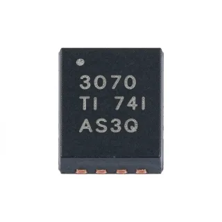
INA2128PA - Dual Instrumentation Amplifier | Texas Instruments
MPN: INA2128PA ✓ فعالINA2128PA نمای کلی
An instrumentation amplifier is a precision analog signal-conditioning IC that amplifies the difference between two input voltages while rejecting signals common to both inputs. Its internal three-op-amp architecture supports accurate differential measurements from low-level sensors. Within the broader semiconductor hierarchy, an instrumentation amplifier belongs to the amplifier IC and analog signal-conditioning categories, where it sits between a sensor or bridge and a measurement, control, or data-conversion system.
Key features include a maximum offset voltage of 50 µV, maximum offset drift of 0.5 µV/°C, maximum input bias current of 5 nA, and minimum common-mode rejection of 120 dB. A single external resistor sets the gain from 1 to 10,000. The dual configuration provides two independent amplifier channels, allowing one package to serve differential measurements or multiple sensor inputs.
The current-feedback input circuitry is the principal performance feature. Unlike a voltage-feedback instrumentation amplifier that loses bandwidth as gain increases, the INA2128 family retains useful bandwidth at high closed-loop gain; the specified bandwidth is 200 kHz at gain 100. The three-op-amp topology also makes the input bias-current behavior relatively insensitive to source impedance, which is valuable when the source is a strain gauge, thermocouple, bridge, or other high-impedance sensor.
Typical applications include bridge-based pressure and load-cell measurements, biomedical instrumentation, current-loop sensing, precision data acquisition, and low-level differential signal conditioning. The ±40 V input protection expands the usable fault-tolerance range, but it does not permit operation beyond the device's stated supply-voltage ratings. Designers should still limit input transients and maintain common-mode voltage within the operating region described by the manufacturer datasheet.
The primary design consideration is gain-setting resistor selection because the external resistor determines gain while also affecting bandwidth, noise, and allowable operating range. Place the gain-setting resistor close to the corresponding gain resistor pins, maintain symmetrical input routing, provide adequate supply bypassing, and use a stable reference ground. This page combines device specifications, application guidance, lifecycle information, and drop-in alternative evaluation for faster engineering selection.
For a dual-channel instrumentation amplifier where PCB area is limited, the INA2128PA provides a direct fit in a 16-pin PDIP footprint. The through-hole package also supports prototype and industrial repair workflows where a surface-mount assembly process would add unnecessary handling complexity.
جایگزینهای drop-in برای INA2128PA — همان پکیج، سازگار پینبهپین. قطعات با پکیج متفاوت که نیاز به تغییر PCB دارند مستثنی هستند.
هیچ جایگزین مستقیمی برای این محصول موجود نیست.
درخواست جایگزینINA2128PA حداکثر مقادیر مجاز و مشخصات الکتریکی
| Amplifier Type | Dual instrumentation amplifier |
| Architecture | Three-op-amp current-feedback architecture |
| Number of Channels | 2 channels |
| Gain Range | 1 to 10,000 |
| Gain Setting | 1 external resistor |
| Bandwidth at Gain 100 | 200 kHz |
| Offset Voltage | 50 µV maximum |
| Offset Voltage Drift | 0.5 µV/°C maximum |
| Input Bias Current | 5 nA maximum |
| Common-Mode Rejection | 120 dB minimum |
| Input Protection Range | ±40 V |
| Supply Voltage Range | ±18 V |
| محدوده دمای کاری | -40°C to +85°C |
| بستهبندی | 16-pin plastic DIP |
| نوع نصب | Through-hole |
راهنمای پیکربندی پین INA2128PA 16-pin plastic dip
پیکربندی پین برای INA2128PA (پکیج 16-pin plastic dip). این قطعه آنالوگ دارای پینهای ورودی، خروجی و تغذیه است. برای پیکربندیهای پین offset null، جبرانسازی و فعالسازی به دیتاشیت سازنده مراجعه کنید. ایدهآل برای مدارهای شرطیسازی سیگنال و تقویتکننده.

داده پینآوت تفصیلی موجود نیست برای INA2128PA.
به دیتاشیت برای پیکربندی کامل پینها.
کاربردهای معمول
INA2128PA مناسب است برای 6 کاربردs: Load-Cell and Weighing Systems, Precision Bridge Pressure Sensing, Biomedical Signal Conditioning, Current-Shunt Instrumentation, Industrial Data Acquisition, Low-Level Sensor Interfaces.
Load-Cell and Weighing Systems
The INA2128PA suits dual-channel load-cell measurement because each channel can amplify a small differential bridge voltage with an externally selected gain from 1 to 10,000. Its 50 µV maximum offset and 0.5 µV/°C maximum drift help limit errors when the useful signal is close to the amplifier noise floor. The 200 kHz bandwidth at gain 100 is sufficient for many weighing, force, and industrial measurement channels. Place the gain resistor close to its pins and route both bridge inputs symmetrically to minimize thermal gradients and unwanted pickup.
Precision Bridge Pressure Sensing
For resistive pressure and displacement bridges, the INA2128PA provides two differential input channels, a gain range of 1 to 10,000, and 120 dB minimum common-mode rejection. The common-mode rejection helps suppress bridge excitation ripple and coupled industrial noise before the millivolt-level differential signal reaches the ADC. With 200 kHz bandwidth at gain 100, the device can support responsive pressure monitoring without adding a separate analog frontend for each channel. Confirm that bridge excitation, input common-mode voltage, and sensor impedance stay within the manufacturer operating limits.
Biomedical Signal Conditioning
The INA2128PA can condition two low-level differential biomedical signals where low offset, low input bias current, and adjustable gain are important. Maximum input bias current of 5 nA limits the disturbance introduced into high-impedance sources, while 50 µV maximum offset and 0.5 µV/°C maximum drift support stable measurements across temperature. The dual channels can serve paired sensor inputs, but medical designs must independently validate patient protection, isolation, noise, and applicable regulatory requirements rather than relying only on the IC specifications.
Current-Shunt Instrumentation
The INA2128PA is useful for measuring the voltage developed across a precision shunt in a grounded or differential current-sense circuit. A gain of 1 to 10,000 allows the shunt voltage to be expanded for an ADC input, and the current-feedback architecture preserves 200 kHz bandwidth at gain 100. The ±40 V input-protection rating provides additional transient margin, although it does not replace a properly rated external protection network. Check shunt common-mode voltage against the supply rails and use Kelvin routing to minimize trace resistance.
Industrial Data Acquisition
Two independent INA2128PA channels provide compact differential analog conditioning for industrial data-acquisition boards. The device combines adjustable gain, 200 kHz bandwidth at gain 100, 120 dB minimum common-mode rejection, and protection to ±40 V in one 16-pin PDIP package. This is useful where sensors produce small differential signals over a noisy common-mode environment. The through-hole package also simplifies prototype rework and manual inspection, while close gain-resistor placement and careful grounding remain essential for repeatable measurements.
Low-Level Sensor Interfaces
The INA2128PA fits general-purpose interfaces for thermocouples, strain gauges, resistance sensors, and other low-level differential sources. Its low input bias current of 5 nA maximum reduces errors with high source impedance, while the broad 1-to-10,000 gain range allows one architecture to cover several signal amplitudes. The dual package can process two sensors with matching amplifier performance. Select the gain from the sensor output and required bandwidth, then verify cold-junction compensation, polarity, grounding, and input filtering separately for each channel.
دادههای مرجع مهندسی برای INA2128PA — مقایسه، راهنمای طراحی و اطلاعات انطباق.
راهنمای انتخاب
مقایسه با جایگزینها
| پارامتر | این محصول |
|---|---|
| Package | 16-pin plastic DIP |
| Brand | Texas Instruments |
| Number of Channels | 2 channels |
| Amplifier Architecture | Three-op-amp current-feedback instrumentation amplifier |
| Gain Range | 1 to 10,000 |
| Bandwidth at Gain 100 | 200 kHz |
| Offset Voltage | 50 µV maximum |
| Offset Drift | 0.5 µV/°C maximum |
| Input Bias Current | 5 nA maximum |
| Common-Mode Rejection | 120 dB minimum |
| Supply Voltage Range | ±18 V |
| Input Protection | ±40 V |
تفاوتهای کلیدی
- Two instrumentation-amplifier channels in one package (در مقابلSingle-channel instrumentation-amplifier devices)
- Current-feedback bandwidth behavior (در مقابلVoltage-feedback instrumentation-amplifier devices)
- Precision DC performance for low-level signals (در مقابلGeneral-purpose operational amplifiers)
یادداشتهای طراحی
Place the external gain-setting resistor directly between the two gain-resistor pins of each channel, keeping the connection short and away from high-current switching nodes. Route the differential inputs as a closely matched pair and provide a quiet analog ground at the device. Because the INA2128PA uses current-feedback input circuitry, excessive loop area can increase parasitic feedback and reduce stability.
Design the source impedance and gain-resistor combination for stable operation across the complete frequency range. Use the Texas Instruments INA2128 datasheet gain-selection table to select the gain resistor, and check the resulting bandwidth and output-swing limits. Do not add large input capacitance directly to a high-gain channel unless the application circuit and stability requirements have been evaluated.
The ±40 V input rating is a protection specification, not permission to operate every input continuously at that voltage. Verify the applied common-mode voltage, supply rails, and transient duration against the operating limits in the manufacturer datasheet. For bridge and shunt sensing, confirm that the input common-mode voltage remains inside the usable range at every bridge excitation or current level.
Bypass each supply rail close to the device and keep the return path short to reduce supply-impedance feedback. The INA2128PA supports ±18 V, but the usable signal range also depends on the selected supply amplitude and output headroom. Decouple both channels against shared supply disturbances, especially when one channel handles a large signal and the other measures a small sensor output.
اطلاعات انطباق
The exact ordering-code compliance declarations are not stated in the cited component documentation. Confirm RoHS, REACH, lead-free, halogen-free, and conflict-minerals status with Texas Instruments before using the part in a regulated design.