Électromécanique
Sous-catégories
Produits (57)

SR-MT9041A-R - Matter over Thread + ZigBee 1CH Smart Relay | Sunricher
The Sunricher SR-MT9041A-R is a Matter over Thread + ZigBee Dual Tech in-wall smart relay module designed for ON/OFF control of connected lighting and electrical loads, housed in a compact plastic enclosure sized for standard EU-style wall boxes. It supports one channel of output with a maximum load current of 4.3 A for resistive loads and 1.7 A for capacitive or inductive loads, while operating from a universal 100-240 Vac input and providing a switched 100-240 Vac output to the load. A Matter over Thread + ZigBee Dual Tech Smart Relay Module is a wireless, behind-the-switch actuator that combines a low-power IEEE 802.15.4 radio (Thread) with a ZigBee 3.0 stack so the same in-wall module can join either a Matter fabric or a legacy ZigBee network. These dual-protocol modules sit in the smart-home device hierarchy between a basic ZigBee relay and a pure Matter device, and they belong to the broader category of in-wall smart switches and lighting controllers used for retrofit and new-build residential automation. Key features of the SR-MT9041A-R include 100-240 Vac universal input, switched 100-240 Vac output, 4.3 A resistive / 1.7 A capacitive-inductive load rating, 3 W standby power consumption, screw-terminal input and output wiring, integrated active power and energy metering, overload and overheat protection, and Touchlink commissioning plus ZigBee Green Power kinetic-switch support. App control is delivered through Matter-certified ecosystems such as Apple Home, Amazon Alexa, and Google Home, and the module supports both remote app control and local push-button control from a traditional wall switch. From an architectural standpoint, the dual-protocol radio design uses shared 2.4 GHz IEEE 802.15.4 silicon running concurrent Thread and ZigBee 3.0 protocol stacks, with onboard firmware selecting the active commissioning path during provisioning. The internal switching element is a bistable or latching relay suitable for 100-240 Vac mains, and the metering chain is a shunt-plus-SoC ADC that reports active power and cumulative energy back to the gateway for energy-monitoring dashboards. Typical applications include retrofit ON/OFF control of ceiling luminaires, wall sconces, exhaust fans, and smart outlets in residential and hospitality installations. Because the module fits behind a conventional wall switch and is rated for the European 100-240 Vac mains, it is well suited to whole-home Matter deployments where consumers want app, voice, and physical-switch control of the same load without rewiring. When designing with the SR-MT9041A-R, confirm that the connected load stays within the 4.3 A resistive or 1.7 A capacitive/inductive derating curve and that the wall box provides adequate volume for the module's 0.1 kg plastic housing and heat dissipation at full load. This page synthesizes Sunricher manual data, distributor pricing, and protocol-level drop-in alternatives not collated in any single manufacturer datasheet.
SR-MT9101SAC-HP-SWITCH-B - 16A Matter over Thread Smart Relay | Sunricher
The Sunricher SR-MT9101SAC-HP-SWITCH-B is a 16 A Matter-over-Thread in-wall smart relay module with dual Matter + ZigBee 3.0 radio support, designed for high-load on/off switching of lighting and appliances in residential and light-commercial smart-home installations. The module accepts 100-240 VAC mains input and provides a 16 A maximum switched output (3680 W incandescent, 1220 W LED per channel) in a compact in-wall form factor intended to fit behind a standard wall box. An in-wall smart relay (also called a smart switch module or in-line relay) is a wireless-controlled switching device installed inside a wall outlet or junction box to provide remote on/off control of a connected load. Smart relays sit at the appliance/lighting tier of the home-automation hierarchy (load -> smart relay -> wireless protocol -> border router -> cloud/ecosystem -> user app/voice assistant). Unlike Wi-Fi smart plugs, Thread-based relays use a low-power IEEE 802.15.4 mesh that requires a Thread Border Router (for example, Apple HomePod mini, Google Nest Hub, or Amazon Echo with Thread support) to communicate with the home Wi-Fi and the user's preferred Matter ecosystem. Key features include 16 A relay contact rating, 100-240 VAC universal mains input, Matter-over-Thread primary radio, plus a ZigBee 3.0 fallback radio for dual-protocol operation. The module requires a neutral wire (N) for powering its radio and control circuitry, and pairs by scanning a Matter QR code printed on the device. Once commissioned, the relay can be exposed to Apple Home, Amazon Alexa, Google Home, and SmartThings simultaneously through standard Matter multi-admin capability, and can additionally be controlled by ZigBee coordinators thanks to the dual radio. The device integrates a 16 A latching or non-latching mechanical relay with zero-cross switching for reduced inrush stress, an AC-DC converter for internal power, and a multi-protocol SoC running both a Matter (Thread) stack and a ZigBee 3.0 stack on the same module. The on-board firmware supports OTA updates via Thread and ZigBee, allowing manufacturers and integrators to push compatibility fixes. A small status LED reports pairing state and current load condition during commissioning. Typical applications include retrofitting smart on/off control into existing wall switch boxes for ceiling lights, fans, and AC outlets, and building energy-management systems where a compact 16 A relay with both Matter and ZigBee support is required. Because the module is rated for high inrush loads (up to 3680 W incandescent / 1220 W LED), it is well suited to both resistive lighting and motor loads. When designing with this device, ensure the wall box has sufficient depth for the module body, provide a reliable neutral connection, and verify that the installation site has adequate Thread mesh coverage or a nearby ZigBee coordinator for commissioning. This product page synthesises distributor pricing, drop-in alternatives, and practical design notes from manufacturer documentation and integrator references.
ST31000640SS - 1TB SAS 7200RPM Enterprise HDD | Seagate
The Seagate ST31000640SS is a 1 TB enterprise-class 3.5-inch hard disk drive spinning at 7200 RPM with a SAS 3 Gb/s interface, designed for Dell PowerEdge servers and EqualLogic iSCSI SAN arrays. It belongs to the Seagate Barracuda ES.2 / Constellation ES family of nearline enterprise drives, using 4 platters with second-generation perpendicular magnetic recording to deliver 1 TB of raw capacity with proven 24x7 reliability. The drive is rated for 7200 RPM spindle speed, a 16 MB or 64 MB cache buffer (variant-dependent), and supports the SAS 3 Gb/s dual-port interface for redundant data paths in mission-critical server and storage-area-network deployments. A nearline SAS HDD is an enterprise-class hard drive optimized for bulk storage workloads where capacity, sustained throughput, and 24x7 availability matter more than ultra-low latency. SAS (Serial Attached SCSI) drives sit above consumer SATA drives in the storage hierarchy - SAS -> enterprise HDD -> nearline HDD -> desktop HDD - offering dual-porting, command queuing (TCQ), and stricter duty-cycle ratings. The ST31000640SS occupies the nearline tier: bulk capacity at spinning-disk economics with enterprise robustness for backup, archival, and tier-2 storage pools inside Dell PowerEdge servers and EqualLogic PS-series arrays. Key features include 1 TB formatted capacity, 7200 RPM spindle, SAS 3 Gb/s interface, average seek times around 8.5 ms read, and on-drive IOEDC/IOECC data protection. The 3.5-inch form factor plugs directly into Dell Gen-13 PowerEdge hot-swap caddies and EqualLogic PS-series shelves, making it a direct-replacement candidate when refreshing aging server pools. Average sustained transfer rates exceed 100 MB/s, while rotational vibration tolerance and dual-port SAS keep performance stable in dense multi-drive chassis. The drive architecture employs 4 platters with perpendicular recording, a dedicated servo system, and Seagate's PowerChoice idle power management. Native command queuing and tagged command queuing enable the host RAID controller to reorder I/O for higher throughput under mixed random/sequential workloads. The dual-port SAS interface delivers multipath I/O for redundant controller paths in EqualLogic SAN deployments. Typical applications include Dell PowerEdge R-series and T-series server primary boot and bulk storage volumes, EqualLogic PS6210E / PS4100E iSCSI SAN capacity expansion, nearline backup targets in SMB and remote-office data centers, RAID-5 or RAID-6 array members for archival storage, and Tier-2 capacity pools behind flash-accelerated read caches. The 1 TB capacity point and 3.5-inch form factor remain broadly deployed in legacy Gen-12/Gen-13 Dell fleets that still accept spinning disks. When designing with this drive, confirm the host backplane accepts 3.5-inch SAS drives at 3 Gb/s link rate and that the RAID controller firmware supports the drive's PI (SCSI Peripheral Interface) version. Mixed-capacity deployments inside a single EqualLogic shelf follow Dell's compatibility matrix - verify the existing shelf firmware revision before hot-adding older nearline drives to newer arrays. This page synthesizes distributor pricing, cross-brand same-capacity alternatives, and practical deployment notes beyond the Seagate product brief, with a focus on the legacy Dell PowerEdge and EqualLogic ecosystem where the ST31000640SS remains in active service.
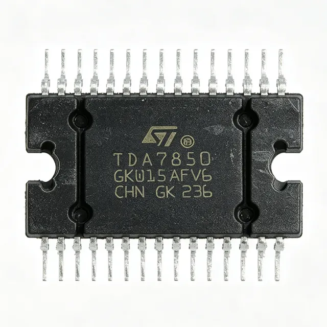
TDA7850 - 4x50W Quad Bridge Car Audio Amplifier | STMicroelectronics
The TDA7850 is a class AB quad bridge car radio amplifier from STMicroelectronics, delivering up to 4x50W into 4Ω loads with a 14.4V supply. It is housed in a Flexiwatt-25 package and designed for high-quality automotive audio systems. Data verified as of 2026-08-05. A class AB amplifier is a type of audio power amplifier that combines the efficiency of class B with the low distortion of class A, making it ideal for automotive head units where both power output and audio fidelity are critical. In the system hierarchy, the TDA7850 sits as the final power amplification stage, following the pre-amplifier and tone control stages, and drives the speakers directly. Key features include a high output power of 4x50W at 4Ω, a wide supply voltage range of 8V to 18V, and a low quiescent current of 120mA. The device also features standby and mute functions for power management, a full set of protections including short-circuit, over-temperature, and load-dump protection, and a very low output noise of 50µV. The Flexiwatt-25 package provides excellent thermal performance with a thermal resistance of 1°C/W, enabling reliable operation in confined automotive environments. The TDA7850 uses a complementary NPN/PNP output stage with a proprietary BiCMOS process, achieving a signal-to-noise ratio of 90dB and a total harmonic distortion of 0.006% at 1kHz. The high PSRR of 80dB minimizes alternator noise, ensuring clean audio output even with engine running. The device also includes a diagnostic pin for fault detection, simplifying system-level testing. Typical applications include car radio head units, aftermarket car audio amplifiers, and marine audio systems. The high output power and low distortion make it suitable for driving 4Ω or 2Ω speakers in multi-channel configurations. The standby and mute pins allow for easy integration with microcontroller-based control systems. When designing with this device, ensure adequate heatsinking to manage the thermal dissipation at high output power. The Flexiwatt-25 package requires a proper thermal interface to the chassis. Also, place the supply and output capacitors close to the IC to minimize EMI and ensure stable operation. This page synthesizes distributor pricing, drop-in alternatives, and practical design notes not found in the ST datasheet, providing a comprehensive resource for engineers selecting a quad bridge amplifier.
TPS1689 - 9-80V 20A Stackable eFuse PMBus | Texas Instruments
The Texas Instruments TPS1689 is a 9V to 80V, 20A stackable integrated hot-swap eFuse (electronic fuse) with PMBus digital telemetry, providing high-current circuit protection and power management with an integrated 3.5mOhm (typ) power FET and a 92V absolute maximum rating. An eFuse is an electronic circuit protection device that guards against overloads, short circuits, and excessive inrush current. Unlike traditional one-time fuses, eFuses are resettable and offer programmable current limits, making them essential for hot-swap applications where boards are inserted into live backplanes. The TPS1689 belongs to the hot-swap controller / integrated eFuse family within the broader power management IC hierarchy. Key features include a PMBus interface for telemetry, control, and configuration, enabling real-time monitoring of voltage, current, and temperature. The integrated FET with RON of 3.65mOhm typ (3.5mOhm in newer datasheet revisions) minimizes conduction losses at 20A. Stackable operation allows multiple TPS1689x devices to be paralleled for higher current, with IMON pins tied together to report total current. The output withstands negative transient voltages up to -5V. Technically, the integrated power FET eliminates external FET driving complexity of discrete hot-swap controllers, while PMBus-programmable current limits, slew rates, and fault responses provide design flexibility. Multiple protection modes cover overcurrent, overvoltage, undervoltage, and thermal shutdown, improving system-level reliability in power distribution trees. Typical applications include 48V backplane hot-swap power, server and datacenter power distribution, telecom equipment, and industrial automation. The 9V-80V operating range fits 48V rails with transient headroom up to the 92V absolute maximum rating. Design with the TPS1689 requires attention to thermal management: PCB copper area and thermal vias are essential at 20A continuous load. Configure PMBus registers so current-limit and fault-response settings match the application protection requirements.
TS117STR - 350V 120mA 1-Form-A Telecom Relay | IXYS
The IXYS Integrated Circuits Division TS117STR is a 350 V, 120 mA, 35 ohm 1-Form-A solid-state relay integrated with an optocoupler in a single 8-pin SMD package, classified under IXYS's OptoMOS multifunction telecom switch family. It provides high sensitivity with low drive power requirements that are TTL/CMOS compatible, making it an ideal solution for many telecom interface applications. The TS117STR combines optically-isolated discrete component functions in one small surface-mount package, replacing multiple discrete parts on telecom line cards, ring-detection circuits, and hook-switches. An OptoMOS solid-state relay is a semiconductor device that replaces an electromechanical relay by using an LED input optically coupled to a MOSFET output stage. The SSRs occupy the broader category hierarchy of solid-state relays -> relays -> electromechanical switches -> discrete switches -> electronic components. The TS117STR family integrates the input-side optical isolation and the output-side switching MOSFET inside one IC, eliminating the need for a separate optocoupler plus discrete MOSFET pair that designers would otherwise have to qualify for surge, isolation, and creepage/clearance separately. This consolidation simplifies BOM management and shortens PCB layout review cycles. Key features include a 350 V peak load voltage rating, 120 mA continuous load current handling, a low 35 ohm on-resistance (RON), and an integrated optically-coupled input that delivers typical 3750 Vrms of galvanic isolation between the input control side and the switched load side. The device operates across -40 C to +85 C, includes zero-voltage-crossing turn-on characteristics to minimize EMI, and is supplied in a small 8-pin SMD gull-wing package suitable for tape-and-reel assembly lines. A current-limiting version is also offered in the same family (TS117STR-L suffix). Typical applications include telephone line interface cards, ring-signal switching, line-test access, on-hook/off-hook switching, line-fault isolation, fax and modem line cards, and T1/E1 interface protection. The integrated optocoupler plus SSR replaces two PCBs' worth of discrete components in traditional telecom designs. When designing with the TS117STR, ensure sufficient creepage distance around the 8-pin SMD land pattern to maintain the rated isolation voltage, and place a TVS diode across the output to clamp inductive ring or test-pulse transients to within the 350 V maximum load voltage rating.

VO14642AABTR - 2A 60V SPST-NO Solid State Relay | Vishay
The Vishay VO14642AABTR is a high-speed single-channel normally-open solid-state relay (SPST-NO, 1 Form A) housed in a 6-pin SMD DIP package (0.300 inch, 7.62 mm). It is constructed as a multi-chip hybrid device that combines a high-efficiency infrared LED on the input side with high-performance MOSFET switches on the output side, delivering a maximum load current of 2 A and a maximum load voltage of 60 V in AC/DC or DC-only configurations. The relay features typical on/off switching times below 800 microseconds and a maximum on-resistance RON of 0.25 ohm, enabling clean bounce-free switching. A solid-state relay (SSR) is an electronic switching device that uses semiconductor output elements (typically MOSFETs, IGBTs, or thyristors) instead of mechanical contacts to switch load circuits. SSRs belong to the broader hierarchy: optoisolator -> solid-state relay -> electromechanical relay -> switching component. The VO14642AABTR integrates an optical isolation barrier rated at 5300 VRMS, providing galvanic isolation between the low-voltage control logic and the high-voltage load. Compared with electromechanical relays, SSRs offer silent operation, no contact bounce, faster switching, and immunity to mechanical wear, at the cost of higher on-resistance and the need for thermal management. Key features include a low-input forward current enabled by an efficient infrared LED, TTL/CMOS-compatible input logic, pure tin lead-free plating, and tape-and-reel packaging for high-volume SMD assembly. The DIP-6 footprint (also described as SMD-6 or 6-pin PDIP SMD) is a familiar, easy-to-place form factor that simplifies PCB layout. The VO14642AABTR supports operating temperatures up to +85 C and is RoHS compliant. A high input-to-output isolation voltage of 5300 VRMS makes it suitable for safety-critical systems requiring reinforced isolation. Typical applications include industrial automation I/O modules, programmable logic controller (PLC) output cards, battery management systems, solenoid and actuator drivers, medical equipment signal switching, and instrumentation multiplexing. The bounce-free switching characteristic is particularly valuable in measurement systems that are sensitive to mechanical contact transients. When designing with the VO14642AABTR, pay attention to the thermal path: even with a low RON of 0.25 ohm, a 2 A load dissipates approximately 1 W in the output MOSFET. Provide adequate copper area on the PCB to keep the junction temperature within safe limits. A reverse-polarity protection diode across the load is recommended for inductive loads such as solenoids or relays. This page combines distributor pricing, drop-in alternative candidates, and application design notes drawn from the manufacturer datasheet and verified distributor listings as of 2026-10-05.

VOR1142M4 - 400V SPST-NO Solid-State Relay | Vishay
The Vishay VOR1142M4 is a 400 V SPST-NO (1 Form A) solid-state photo-coupled relay (Photorelay) housed in a 4-pin SOP package measuring 4.57 mm (0.180 inch) wide. It uses a GaAlAs infrared LED on the input side and dual MOSFETs on the output side, providing galvanic isolation between low-voltage control logic and high-voltage load switching. What is a solid-state relay (SSR)? A solid-state relay is an electronic switching device that performs the same function as an electromechanical relay but contains no moving parts. SSR technology replaces mechanical contacts and armatures with semiconductor switches (typically MOSFETs, IGBTs, or thyristors) and provides galvanic isolation between input and output through an optocoupler (LED + photodetector), transformer, or RF coupler. Compared with electromechanical relays, SSRs offer silent operation, unlimited mechanical endurance, faster switching speeds, bounce-free outputs, and high resistance to shock and vibration. The VOR1142M4 belongs to the photorelay sub-family, in which an IRED drives MOSFET output switches directly through optical coupling. Key specifications include a maximum load voltage of 400 V, a typical on-state resistance of 19 ohm, a continuous load current rating of 140 mA, current-limit protection, an isolation test voltage of 3750 Vrms, and a high-reliability construction. The 4-SOP package footprint is industry-standard for miniature photorelays, enabling direct substitution on existing PCB layouts. Typical on-resistance variation with temperature is also low, allowing stable operation across the -40 C to +85 C industrial temperature range. In the output stage, the dual-MOSFET architecture provides bidirectional AC/DC switching capability through two MOSFETs connected back-to-back, supporting both polar and AC-load applications. The GaAlAs IRED provides high radiant intensity at low forward current (typically 5 mA), enabling low-power microcontroller-driven control with a guaranteed CTR/IFT specification across temperature. Typical applications include general telecom switching, security equipment, metering systems, automatic test equipment, battery monitoring, and industrial control isolation. Designers select photorelays in place of mechanical relays when silent switching, long-term reliability, low power consumption, and immunity to shock/vibration are required. When designing with this device, ensure that the load current does not exceed the 140 mA continuous rating and that the peak load voltage remains below 400 V. Always include a snubber or flyback protection when switching inductive loads, and add an input-side resistor to limit the IRED forward current to the recommended maximum (10 mA) for long-term reliability. This page synthesizes distributor pricing, cross-reference alternatives, and practical design considerations not found in the manufacturer datasheet alone, giving engineers a single reference for sourcing and second-sourcing the VOR1142M4.
ZZCATCH-20260819 - Oil Catch Can | ZZPerformance | Engine Protection
The ZZCATCH-20260819 is an oil catch can manufactured by ZZPerformance, designed to intercept blow-by gases and oil vapor from the PCV (Positive Crankcase Ventilation) system before they enter the intake manifold. This device helps reduce carbon buildup on intake valves, improving engine performance and longevity. It is a mechanical component, not an electronic semiconductor, and is typically installed in the PCV line between the crankcase and the intake manifold. An oil catch can is a simple yet effective device used in internal combustion engines to separate oil mist and vapors from the crankcase ventilation gases. It works by allowing the blow-by gases to pass through a baffle or filter medium, where the oil droplets condense and collect in a reservoir, while the cleaned gases continue to the intake. This prevents oil from coating the intake valves, which is especially important in direct-injection engines where fuel is not sprayed on the valves to clean them. Key features of the ZZCATCH-20260819 include a durable aluminum or steel construction, a large capacity reservoir, and a simple installation process that requires no special tools. The device is designed to be maintenance-friendly, with a drain valve or removable bottom for easy emptying of collected oil. It is compatible with a wide range of vehicles, particularly those with turbocharged or supercharged engines that produce higher crankcase pressures. Technically, the catch can operates passively, relying on the pressure differential between the crankcase and the intake manifold to drive the blow-by gases through the device. The internal baffle design maximizes oil separation efficiency while minimizing flow restriction, ensuring that the PCV system continues to function correctly. The device does not require any electrical connections or electronic control, making it a purely mechanical addition to the engine. Typical applications include high-performance street cars, track vehicles, and daily drivers with modified engines. It is particularly beneficial for direct-injection engines, where carbon buildup on intake valves is a known issue. The ZZCATCH-20260819 is also suitable for use in both gasoline and diesel engines, provided the PCV system is compatible. When installing this catch can, it is important to ensure proper routing of the PCV hoses and to check the device periodically for accumulated oil. The reservoir should be emptied regularly to prevent overflow, which could lead to oil being drawn into the intake. The device is designed to be a low-maintenance addition to the engine, but regular inspection is recommended.