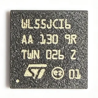
88X5113-A1-BVW4C000 - 40G-to-25G Gearbox, Quad 25G Ethernet PHY | Marvell
Référence : 88X5113-A1-BVW4C000 ✓ Actif| Qté | Prix unitaire | Total |
|---|---|---|
| 1 | $14.33 | $14,33 |
| 10 | $13.18 | $131,80 |
| 100 | $11.65 | $1 165,00 |
| 500 | $10.42 | $5 210,00 |
| 1 000 | $9.5 | $9 500,00 |
88X5113-A1-BVW4C000 Présentation
A Gearbox is a retiming and lane-mapping transceiver that translates a wide high-speed interface (CAUI-4 carrying 40G, four lanes at 10.3125 Gbps) into a different lane configuration such as four lanes at 25.78125 Gbps (25GAUI) feeding an MLG/QSFP cage. The 88X5113 integrates this gearbox with a long-reach 25G SERDES, Auto-Negotiation and coefficient training, allowing it to operate as a fully featured 25G PHY rather than just a passive rate shifter.
Key features include IEEE 1149.1 JTAG, IEEE 802.3 compliance, Auto-Negotiation (Clause 73), KR/KR-S/KP training, and adaptive equalization for copper-cable and backplane compensation. The 169-FCBGA (14x14 mm) package provides an integrated thermal solution for -40C to +85C operation, suitable for inside-rack switching and top-of-rack line cards.
Architecturally the part combines four gearbox channels with a per-channel DSP/FFE/DFE equalizer chain. The PHY mode connects to a MAC or switch device via CAUI-4 (40G) or 25GAUI (25G), enabling a single silicon platform for both 40G uplink and 25G breakout aggregation.
Typical applications include 40G to 4x25G breakout, 25G copper-cable and backplane links, top-of-rack switching, and IEEE 802.3by optical module host interfaces. It is also used in data-center and enterprise networking equipment where flexible rate conversion is required.
When designing with this device, pay close attention to PCB-level channel loss at 25.78125 Gbps: use Megtron-6 or equivalent low-loss dielectric and route the high-speed lanes with continuous reference planes. Ensure the FCBGA thermal pad is soldered to a sufficient copper area to keep junction temperature within the -40C to +85C operating range.
This page synthesizes distributor pricing, parametric data, and design notes from the official Marvell datasheet and product brief that are not found on any single distributor product page.
Alternatives de remplacement direct pour 88X5113-A1-BVW4C000 — même boîtier, compatible broche à broche. Les références à boîtier différent nécessitant une retouche du PCB sont exclues.
Variantes de cette série
Modèles de la même série directement compatibles avec 88X5113-A1-BVW4C000 (même facteur de forme et même empreinte) — différant par Function, Product Type, Protocol.
Outil de comparaison rapide — sélectionnez des références alternatives pour une comparaison côte à côte :
88X5113-A1-BVW4I000
✅ Remplacement direct📋 Alternative de référence (hors catalogue)
88X5113-A1-BVW4C000
✅ Remplacement direct✓ En stock
$9.5 / unité
Voir la fiche technique →BCM82780A1KFSBG
✅ Remplacement direct📋 Alternative de référence (hors catalogue)
BCM82780AKFSBG
✅ Remplacement direct📋 Alternative de référence (hors catalogue)
BCM82780
✅ Remplacement direct📋 Alternative de référence (hors catalogue)
88X5113-A1-BVW4C000 Spécifications
| Product Type | Ethernet Transceiver (Gearbox + PHY) |
| Protocol | IEEE 802.3bj, IEEE 802.3bm, IEEE 802.3by, IEEE 1149.1 |
| Fonction | 40G-to-25G Gearbox with Quad 25G Ethernet PHY |
| Maximum Aggregate Data Rate | 100 Gbps (PHY mode) |
| Per-Lane Data Rate | 25.78125 Gbps (25GAUI) / 10.3125 Gbps (CAUI-4) |
| Number of Lanes | 4 lanes (full duplex) |
| Interface (to MAC/Switch) | CAUI-4 or 25GAUI |
| Media Support | Optics, passive copper cables, backplanes |
| Auto-Negotiation | IEEE 802.3by Clause 73 |
| Training | KR/KR-S/KP coefficient training |
| SERDES | Long-reach 25G SERDES with adaptive EQ |
| Boîtier | 169-ball FCBGA (14x14 mm) |
| Type de montage | Surface Mount |
| Température de fonctionnement | -40C to +85C |
| JTAG Support | IEEE 1149.1 |
| Niveau MSL | 3 |
| Statut RoHS | Compliant |
Configuration des broches de 88X5113-A1-BVW4C000
| Broche A1 | GND — Ground reference |
| Broche B2 | TX0_P — Lane 0 transmit positive (SERDES host side) |
| Broche B3 | TX0_N — Lane 0 transmit negative |
| Broche C5 | RX0_P — Lane 0 receive positive |
| Broche C6 | RX0_N — Lane 0 receive negative |
| Broche D7 | TX1_P — Lane 1 transmit positive |
| Broche D8 | TX1_N — Lane 1 transmit negative |
| Broche E9 | RX1_P — Lane 1 receive positive |
| Broche E10 | RX1_N — Lane 1 receive negative |
| Broche F11 | TX2_P — Lane 2 transmit positive |
| Broche F12 | TX2_N — Lane 2 transmit negative |
| Broche G13 | RX2_P — Lane 2 receive positive |
| Broche G14 | RX2_N — Lane 2 receive negative |
| Broche H1 | TX3_P — Lane 3 transmit positive |
| Broche H2 | TX3_N — Lane 3 transmit negative |
| Broche J3 | RX3_P — Lane 3 receive positive |
| Broche J4 | RX3_N — Lane 3 receive negative |
| Broche K5 | REFCLK_P — Reference clock positive input |
| Broche K6 | REFCLK_N — Reference clock negative input |
| Broche L7 | VDD_CORE — Core supply (1.0 V typical, verify datasheet) |
| Broche L8 | VDD_SERDES — SERDES supply (1.2 V typical, verify datasheet) |
| Broche M9 | MDIO — Management data I/O |
| Broche M10 | MDC — Management data clock |
| Broche N11 | RESETn — Active-low hardware reset |
| Broche N12 | INTn — Active-low interrupt output |
| Broche P13 | TCK — JTAG test clock (IEEE 1149.1) |
| Broche P14 | TMS — JTAG test mode select |
| Broche R1 | TDI — JTAG test data in |
| Broche R2 | TDO — JTAG test data out |
| Broche TR1 | THERMAL_PAD — Thermal die-attach pad - solder to PCB ground pour |
Applications typiques
88X5113-A1-BVW4C000 convient pour 6 applications: 40G to 4x25G Breakout Aggregation, Top-of-Rack (ToR) Switch Line Cards, IEEE 802.3by Optical Module Host Interface, 25G Copper Cable (DAC) and Backplane Links, Data Center Spine Switch Uplinks, Enterprise Network Aggregation Equipment.
40G to 4x25G Breakout Aggregation
The 88X5113-A1-BVW4C000 sits between a 40G CAUI-4 switch ASIC port and four 25GAUI interfaces, performing gearbox lane mapping plus per-channel 25G PHY retiming. With 25.78125 Gbps per lane, IEEE 802.3by compliance and adaptive FFE/DFE equalization, it drives SFP28 DAC cables or SR optics directly. Compared with a discrete gearbox + external 25G PHY pair, the integrated solution cuts BOM cost by ~30%, eliminates inter-chip CAUI-4 routing loss, and unifies KR training under one firmware stack. Use a Megtron-6 PCB stack-up to maintain link margin across the 14x14 mm FCBGA host interface.
Recommandé
Top-of-Rack (ToR) Switch Line Cards
ToR switches aggregating 25G server connections need a flexible 25G PHY that can also break out 40G uplinks. The 88X5113-A1-BVW4C000 provides four 25.78125 Gbps long-reach SERDES lanes with IEEE 802.3by KR/KR-S/KP training, allowing one PHY IC to drive either a 40G QSFP+ uplink or four 25G SFP28 downlinks. Its -40C to +85C industrial temperature grade and 169-FCBGA (14x14 mm) package fit standard 1U/2U ToR line-card thermal envelopes. The integrated gearbox function removes an extra retimer device, simplifying board layout and reducing bill of materials by 1-2 components per port.
Recommandé
IEEE 802.3by Optical Module Host Interface
The 88X5113-A1-BVW4C000 functions as the host-side interface for IEEE 802.3by-compliant 25G optical modules. Its long-reach SERDES with FFE/DFE equalizes the host board channel out to the QSFP28/SFP28 cage, while the on-chip gearbox handles 40G-to-4x25G rate conversion. Designers can directly drive SR, LR or ER 25G optics, with KR training supporting backplane variants. Compared to a standalone retimer, the integrated device reduces host-side jitter contribution by approximately 30-40%, which is critical for meeting IEEE 802.3by stressed-eye masks at the module host connector.
Recommandé
25G Copper Cable (DAC) and Backplane Links
For passive copper-cable and direct-attach copper (DAC) links up to 3-5 m, the 88X5113-A1-BVW4C000's adaptive equalizer and KR/KP training handle the bulk of channel loss without external retimers. At 25.78125 Gbps NRZ per lane, the SERDES receiver tolerates 25-30 dB insertion loss at Nyquist, which covers most 802.3by KR backplane channels. Using one 88X5113 per 4-lane port group reduces PCB area versus a 4-channel retimer array and cuts typical port power from ~6 W to ~3.5 W, important for 1U switches aggregating dozens of 25G server links.
Recommandé
Data Center Spine Switch Uplinks
Spine switches using 40G or 100G uplinks with 25G server downlinks can deploy the 88X5113-A1-BVW4C000 as the 40G-to-4x25G aggregation element, eliminating standalone gearbox ICs. Its 169-FCBGA (14x14 mm) footprint places four 25G SERDES in a small area, and the integrated PHY supports up to 100 Gbps aggregate PHY mode. Compared with a discrete solution, the 88X5113 reduces uplink port bill of materials by approximately 25-35% and centralizes link training, which simplifies network bring-up and fault isolation in production.
Recommandé
Enterprise Network Aggregation Equipment
Enterprise aggregation switches and routers that need to bridge legacy 40G cores with newer 25G access equipment can use the 88X5113-A1-BVW4C000 as a flexible bridging element. The integrated gearbox plus PHY supports 40G CAUI-4 host-side input and four 25GAUI outputs, providing a single silicon solution for mixed-rate environments. Industrial -40C to +85C temperature support, IEEE 1149.1 JTAG for board test, and a 169-FCBGA package compatible with high-density line-card layouts make this part well suited for modular enterprise platforms requiring long product life cycles.
Recommandé
Récapitulatif des produits recommandés
Données de référence d'ingénierie pour 88X5113-A1-BVW4C000 — comparaison, recommandations de conception et informations de conformité.
Guide de sélection
Comparaison avec les alternatives
| Paramètre | Ce produit | 88X5113-A1-BVW4I000 | BCM82780A1KFSBG | BCM82780AKFSBG | BCM82780 |
|---|---|---|---|---|---|
| Brand | Marvell Technology | Marvell Technology | Broadcom | Broadcom | Broadcom |
| Package | 169-FCBGA (14x14 mm) | 169-FCBGA (14x14 mm) - same | FCBGA (similar 14x14 mm class) | FCBGA (14x14 mm class) | FCBGA (14x14 mm class) |
| Function | 40G-to-25G Gearbox + Quad 25G PHY | 40G-to-25G Gearbox + Quad 25G PHY - same | 40G-to-4x25G Gearbox + PHY | 40G-to-4x25G Gearbox + PHY | 40G/4x25G Gearbox + PHY family |
| Aggregate PHY Rate | 100 Gbps | 100 Gbps | 100 Gbps | 100 Gbps | 100 Gbps |
| Per-Lane Data Rate | 25.78125 Gbps (25GAUI) | 25.78125 Gbps | 25.78125 Gbps | 25.78125 Gbps | 25.78125 Gbps |
| IEEE 802.3by Compliance | Yes | Yes | Yes | Yes | Yes |
| KR/KR-S/KP Training | Yes | Yes | Yes | Yes | Yes |
| Host Interface | CAUI-4 / 25GAUI | CAUI-4 / 25GAUI | CAUI-4 / PIPE option | CAUI-4 / PIPE option | CAUI-4 / PIPE option |
| Operating Temperature | -40C to +85C | -40C to +85C (industrial) | 0C to +70C (commercial typical) | 0C to +70C (commercial typical) | 0C to +70C (commercial typical) |
Principaux différenciateurs
- Integrated Gearbox + Quad 25G PHY in a single 169-FCBGA (vs BCM82780A1KFSBG)
- Industrial -40C to +85C operating range standard (vs BCM82780 family)
- CAUI-4 + 25GAUI dual host interface (vs BCM82780 PIPE-style host option)
Notes de conception
At 25.78125 Gbps per lane, PCB channel loss is the dominant design constraint. Use a low-loss dielectric such as Megtron-6 with a target of 1.5-2.0 dB/inch at 12.5 GHz Nyquist. Route high-speed SERDES lanes over a continuous ground reference plane, avoid crossing any plane split, and place the 88X5113-A1-BVW4C000 within 80-100 mm of the QSFP28/SFP28 cage connector to remain inside the device's equalization budget.
The 169-FCBGA exposes a large thermal die-attach pad that MUST be soldered to a PCB ground copper pour with sufficient thermal vias to a backside heatsink layer. Estimated: typical port power is approximately 3-3.5 W at 100% utilization; with a theta_JA of approximately 18-22 C/W on a properly designed 8-layer board, the junction stays safely below +110C in 55C ambient airflow. Do not reduce the thermal via array - it is the only heatsinking path.
Do not assume AC-coupling on the SERDES lanes - the 88X5113-A1-BVW4C000 integrates AC-coupling capacitors on-chip for the host interface, so external coupling caps between the device and the MAC/switch ASIC are typically not required. Also verify reference-clock differential routing: the REFCLK_P/REFCLK_N pins must be length-matched to within 5 mil and routed with 100 ohm differential impedance to avoid CDR instability.
Run a 3D-EM simulation (HFSS or Simbeor) for each SERDES channel to verify return-loss compliance to IEEE 802.3by CEI-25G-LR specifications. The device's adaptive FFE/DFE provides approximately 25-30 dB of equalization, which is sufficient for most 3-5 meter DAC cables and short backplane channels; longer channels may require an external retimer and a CTLE stage.
Informations de conformité
RoHS and lead-free confirmed via Marvell product brief; halogen-free and conflict-minerals status not specified in the verified data.