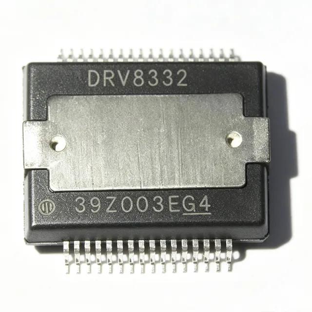
DRV8432DKDR - 52V 14A Dual Full-Bridge Motor Driver | TI
Référence : DRV8432DKDR ✓ Actif| Qté | Prix unitaire | Total |
|---|---|---|
| 1 | $12.5 | $12,50 |
| 10 | $11.25 | $112,50 |
| 100 | $9.8 | $980,00 |
| 500 | $8.75 | $4 375,00 |
| 1 000 | $7.9 | $7 900,00 |
DRV8432DKDR Présentation
A motor driver is an integrated circuit that translates low-power control signals from a microcontroller or DSP into high-current, high-voltage signals capable of driving motors. The DRV8432 belongs to the motor driver category, which is a subset of power management ICs. It integrates four half-bridges (configurable as two full H-bridges) with low RDS(on) MOSFETs (110 mΩ at TJ = 25°C), achieving up to 97% power-stage efficiency. This integration reduces external component count and simplifies PCB layout compared to discrete H-bridge designs.
Key features include advanced protection circuitry: overcurrent protection (OCP), overtemperature protection (OTP), undervoltage lockout (UVLO), and overvoltage protection (OVP). The device supports PWM control with a wide frequency range, and its current regulation capability enables precise torque control in stepper applications. The DRV8432 also features a sleep mode for low-power standby, reducing quiescent current consumption.
Technically, the DRV8432 uses a bootstrap-based gate drive architecture for the high-side N-channel MOSFETs, requiring external bootstrap capacitors. The device provides separate logic and power grounds, and its digital inputs are compatible with 3.3 V and 5 V logic levels. The PWM frequency can be set up to 500 kHz, making it suitable for high-speed switching applications. The thermal pad on the HSSOP package must be soldered to a copper plane for adequate heat dissipation.
Typical applications include brushed DC motor drivers in robotics, industrial automation, and automotive systems; bipolar stepper motor drivers in 3D printers and CNC machines; and solenoid drivers in vending machines and industrial controls. The wide voltage range and high current capability make it versatile for various motor control systems.
When designing with the DRV8432, ensure proper PCB layout with low-inductance paths for high-current loops and adequate thermal vias under the thermal pad. The bootstrap capacitors should be placed close to the respective pins, and the logic supply should be decoupled with a 0.1 µF ceramic capacitor.
Alternatives de remplacement direct pour DRV8432DKDR — même boîtier, compatible broche à broche. Les références à boîtier différent nécessitant une retouche du PCB sont exclues.
Outil de comparaison rapide — sélectionnez des références alternatives pour une comparaison côte à côte :
DRV8432DKD
📋 Alternative de référence (hors catalogue)
DRV8412DDW
📋 Alternative de référence (hors catalogue)
DRV8462DDV
📋 Alternative de référence (hors catalogue)
DRV8262DDV
📋 Alternative de référence (hors catalogue)
DRV8962DDV
📋 Alternative de référence (hors catalogue)
DRV8432DKDR Valeurs maximales et caractéristiques électriques
| Nombre de sorties | 2 (dual full-bridge) |
| Configuration de sortie | 4 half-bridges |
| Voltage - Supply (logic) | 10.8 V ~ 13.2 V |
| Voltage - Load | 0 V ~ 52.5 V |
| Current - Output | 7 A per channel (14 A per bridge) |
| RDS(on) | 110 mΩ at TJ = 25°C |
| Power Stage Efficiency | Up to 97% |
| PWM Frequency | Up to 500 kHz |
| Operating Supply Voltage (Absolute Max) | 70 V |
| Boîtier | 36-HSSOP (PowerPAD) |
| Style de montage | Surface Mount |
| Nombre de broches | 36 |
| Plage de température de fonctionnement | -40°C to +85°C |
| Protection Features | OCP, OTP, UVLO, OVP |
| Statut RoHS | Compliant |
Configuration des broches de DRV8432DKDR
| Broche 1 | GND — Power ground |
| Broche 2 | OUT1 — Half-bridge output 1 |
| Broche 3 | OUT2 — Half-bridge output 2 |
| Broche 4 | VM — Motor supply voltage |
| Broche 5 | OUT3 — Half-bridge output 3 |
| Broche 6 | OUT4 — Half-bridge output 4 |
| Broche 7 | GND — Power ground |
| Broche 8 | BST_A — Bootstrap capacitor for high-side FET A |
| Broche 9 | BST_B — Bootstrap capacitor for high-side FET B |
| Broche 10 | BST_C — Bootstrap capacitor for high-side FET C |
| Broche 11 | BST_D — Bootstrap capacitor for high-side FET D |
| Broche 12 | VDD — Logic supply voltage |
| Broche 13 | GND — Logic ground |
| Broche 14 | IN1 — Logic input for half-bridge 1 |
| Broche 15 | IN2 — Logic input for half-bridge 2 |
| Broche 16 | IN3 — Logic input for half-bridge 3 |
| Broche 17 | IN4 — Logic input for half-bridge 4 |
| Broche 18 | SLEEP — Sleep mode input (active low) |
| Broche 19 | OCP — Overcurrent protection flag output |
| Broche 20 | OTP — Overtemperature protection flag output |
| Broche 21 | UVLO — Undervoltage lockout flag output |
| Broche 22 | OVP — Overvoltage protection flag output |
| Broche 23 | GND — Power ground |
| Broche 24 | OUT1 — Half-bridge output 1 (duplicate) |
| Broche 25 | OUT2 — Half-bridge output 2 (duplicate) |
| Broche 26 | VM — Motor supply voltage (duplicate) |
| Broche 27 | OUT3 — Half-bridge output 3 (duplicate) |
| Broche 28 | OUT4 — Half-bridge output 4 (duplicate) |
| Broche 29 | GND — Power ground |
| Broche 30 | BST_A — Bootstrap capacitor for high-side FET A (duplicate) |
| Broche 31 | BST_B — Bootstrap capacitor for high-side FET B (duplicate) |
| Broche 32 | BST_C — Bootstrap capacitor for high-side FET C (duplicate) |
| Broche 33 | BST_D — Bootstrap capacitor for high-side FET D (duplicate) |
| Broche 34 | VDD — Logic supply voltage (duplicate) |
| Broche 35 | GND — Logic ground |
| Broche 36 | PAD — Exposed thermal pad (solder to ground plane) |
Applications typiques
DRV8432DKDR convient pour 6 applications: Brushed DC Motor Driver, Bipolar Stepper Motor Driver, Solenoid Driver, Robotics Actuator, Industrial Automation, Automotive Systems.
Brushed DC Motor Driver
The DRV8432DKDR drives brushed DC motors with up to 14 A per bridge, making it ideal for robotics, industrial automation, and automotive actuators. Its low RDS(on) (110 mΩ) minimizes power loss, and the wide voltage range (0-52.5 V) supports 12 V, 24 V, and 48 V systems. The integrated protection features (OCP, OTP, UVLO) ensure reliable operation in harsh environments. PWM control up to 500 kHz allows precise speed regulation. For a 24 V motor drawing 10 A, the driver dissipates only 11 W (I²R), which is manageable with proper thermal design.
Recommandé
Bipolar Stepper Motor Driver
The DRV8432DKDR can be configured as a dual full-bridge driver for a single bipolar stepper motor, providing current regulation for precise positioning. It supports up to 14 A per bridge, enabling high-torque stepper motors in 3D printers, CNC machines, and textile equipment. The PWM current regulation ensures smooth microstepping, and the wide voltage range accommodates various motor ratings. The device's thermal pad must be connected to a heatsink for continuous operation at high currents. With a 48 V stepper motor, the driver can achieve high torque while maintaining efficiency.
Recommandé
Solenoid Driver
The DRV8432DKDR can drive solenoids in industrial controls, vending machines, and automotive systems. Its high current capability (up to 14 A) and voltage range (up to 52.5 V) make it suitable for large solenoids. The integrated flyback diodes (via body diodes of MOSFETs) protect the driver from inductive kickback. PWM control allows adjustable holding current, reducing power consumption. The device's protection features prevent damage from overcurrent and overtemperature. For a 24 V solenoid with 5 A holding current, the driver can efficiently regulate the current.
Recommandé
Robotics Actuator
In robotics, the DRV8432DKDR drives DC motors and stepper motors for joint actuation and locomotion. Its high current capability supports powerful actuators, and the wide voltage range allows operation from various battery configurations. The device's small footprint (36-HSSOP) saves PCB space, and the integrated protection features enhance system reliability. PWM control enables precise speed and torque control, essential for robotic movements. For a robot arm with a 12 V motor drawing 8 A, the driver can handle the load with adequate cooling.
Recommandé
Industrial Automation
The DRV8432DKDR is used in industrial automation for conveyor belts, pumps, and valve control. Its robust protection features (OCP, OTP, UVLO) ensure reliable operation in factory environments. The wide voltage range (0-52.5 V) accommodates various industrial supply rails, and the high current capability drives large motors. The device's efficiency (up to 97%) reduces energy consumption and heat generation. For a 48 V conveyor motor drawing 12 A, the driver can operate continuously with proper heatsinking.
Recommandé
Automotive Systems
The DRV8432DKDR is suitable for automotive applications such as power windows, seat adjusters, and cooling fans. Its wide voltage range (up to 52.5 V) handles load dumps and transients, and the protection features prevent damage from short circuits. The device operates over -40°C to +85°C, meeting automotive temperature requirements. For a 12 V automotive fan motor drawing 10 A, the driver can efficiently control the speed. Note that the DRV8432 is not AEC-Q100 qualified, so for strict automotive compliance, consider the DRV8432DKD or other qualified parts.
Recommandé
Récapitulatif des produits recommandés
Données de référence d'ingénierie pour DRV8432DKDR — comparaison, recommandations de conception et informations de conformité.
Guide de sélection
Comparaison avec les alternatives
| Paramètre | Ce produit | DRV8432DKD | DRV8412DDW | DRV8462DDV | DRV8262DDV | DRV8962DDV |
|---|---|---|---|---|---|---|
| Package | 36-HSSOP | 36-HSSOP | 36-HSSOP | 36-HSSOP | 36-HSSOP | 36-HSSOP |
| Brand | Texas Instruments | Texas Instruments | Texas Instruments | Texas Instruments | Texas Instruments | Texas Instruments |
Principaux différenciateurs
- Higher output current (14 A per bridge) compared to DRV8412DDW (vs DRV8412DDW)
- Wide load voltage range (0-52.5 V) supports 48V systems (vs DRV8412DDW)
- Integrated protection features (OCP, OTP, UVLO, OVP) enhance reliability (vs DRV8412DDW)
Notes de conception
The DRV8432DKDR can dissipate significant power at high currents. For example, at 14 A per bridge with RDS(on) of 110 mΩ, each bridge dissipates approximately 21.6 W (I²R). The 36-HSSOP package has a thermal pad that must be soldered to a large copper area on the PCB. Use multiple thermal vias to connect the pad to inner and bottom layers for effective heat spreading. For continuous operation above 10 A, consider adding a heatsink or forced airflow.
Place bootstrap capacitors (typically 0.1 µF) as close as possible to the BST and OUT pins to minimize loop inductance. Use low-ESR ceramic capacitors for the logic supply (VDD) and motor supply (VM) decoupling. The high-current paths (VM, OUT1-4, GND) should be wide and short to reduce parasitic inductance and resistance. Separate power ground and logic ground, connecting them at a single point near the thermal pad.
Do not exceed the absolute maximum supply voltage of 70 V on VM. Ensure the logic supply (VDD) is within 10.8-13.2 V; applying higher voltage can damage the device. The sleep pin (SLEEP) must be pulled high for normal operation; leaving it floating may cause unintended shutdown. Also, ensure the OCP, OTP, UVLO, and OVP flag pins are monitored by the microcontroller to handle fault conditions promptly.
Informations de conformité
RoHS compliant per TI product page. Not AEC-Q100 qualified.







