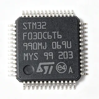
MC908GR60ACFAE - 8-bit HC08 MCU 60KB Flash 48-LQFP | NXP
Référence : MC908GR60ACFAE ✗ Fin de vie| Qté | Prix unitaire | Total |
|---|---|---|
| 1 | $11.5 | $11,50 |
| 10 | $10.35 | $103,50 |
| 100 | $9.2 | $920,00 |
| 500 | $8.05 | $4 025,00 |
| 1 000 | $6.9 | $6 900,00 |
MC908GR60ACFAE Présentation
An 8-bit microcontroller (MCU) is a single-chip computer that integrates a CPU, non-volatile program memory (Flash/ROM), volatile working memory (RAM), and a variety of peripheral interfaces into one package. HC08 microcontrollers belong to the broader category of CISC (Complex Instruction Set Computer) 8-bit controllers, sitting within the hierarchy: 8-bit MCU -> CISC microcontroller -> embedded controller -> semiconductor IC. The M68HC08 architecture is fully upward-compatible at the object-code level with the earlier M6805, M146805, and M68HC05 families, allowing legacy code migration without software rewrites.
Key features include 60KB of Flash program memory organized as 60K x 8, 2KB of on-chip RAM, an 8 MHz internal bus, an integrated 10-bit ADC with up to 24 input channels, dual timer interfaces (TIM1 and TIM2), a Serial Communications Interface (SCI) and a Serial Peripheral Interface (SPI). The CPU08 core delivers an instruction set optimized for C compilers, which simplifies firmware development and accelerates time-to-market for embedded designers.
The MC908GR60ACFAE is targeted at cost-sensitive automotive body electronics and industrial control applications. Typical end products include instrument clusters, body controllers, HVAC modules, sensor interfaces, small motor control boards, and white-goods control boards. Its wide operating voltage range (3.0V to 5.5V typical) and automotive temperature grade (-40C to +125C) make it well suited to under-hood and chassis environments.
When designing with this part, allocate a minimum of 0.5 inch square of PCB copper beneath the exposed thermal pad and follow NXP's recommended decoupling scheme of one 100 nF X7R ceramic capacitor per VDD pin placed within 3 mm of the pin. The Flash memory is specified for at least 10,000 program/erase cycles per sector, so applications requiring heavy in-application reprogramming should plan wear-leveling or external EEPROM augmentation.
Alternatives de remplacement direct pour MC908GR60ACFAE — même boîtier, compatible broche à broche. Les références à boîtier différent nécessitant une retouche du PCB sont exclues.
Variantes de cette série
Modèles de la même série directement compatibles avec MC908GR60ACFAE (même facteur de forme et même empreinte) — différant par Core Architecture, Package / Case, Program Memory Size, RAM Size, Supply Voltage.
Outil de comparaison rapide — sélectionnez des références alternatives pour une comparaison côte à côte :
Aucune alternative de remplacement direct disponible pour ce produit.
Demander des alternativesMC908GR60ACFAE Valeurs maximales et caractéristiques électriques
| Core Architecture | M68HC08 (CPU08) - 8-bit CISC |
| Program Memory | 60 KB Flash (60K x 8) |
| RAM | 2 KB on-chip |
| Maximum Bus Frequency | 8 MHz internal |
| Tension d'alimentation | 3.0 V to 5.5 V (3.3 V / 5 V typical) |
| ADC | 10-bit, up to 24 channels |
| Communication Interfaces | SCI (UART) + SPI |
| Timers | TIM1 and TIM2 (16-bit timer modules) |
| I/O Pins | Up to 40 general-purpose I/O |
| Boîtier | 48-pin LQFP (7x7 mm) |
| Type de montage | Surface Mount |
| Température de fonctionnement | -40 C to +125 C (automotive grade) |
| Object-code Compatibility | M6805, M146805, M68HC05 families |
| Statut RoHS | Compliant |
Configuration des broches de MC908GR60ACFAE
| Broche 1 | PTD0/T1CH0 — Port D I/O / Timer 1 channel 0 |
| Broche 2 | PTD1/T1CH1 — Port D I/O / Timer 1 channel 1 |
| Broche 3 | PTD2 — Port D I/O |
| Broche 4 | PTD3 — Port D I/O |
| Broche 5 | VDD — Supply voltage |
| Broche 6 | VSS — Ground |
| Broche 7 | PTA0 — Port A I/O |
| Broche 8 | PTA1 — Port A I/O |
| Broche 9 | PTA2 — Port A I/O |
| Broche 10 | PTA3 — Port A I/O |
| Broche 11 | PTA4 — Port A I/O |
| Broche 12 | PTA5 — Port A I/O |
| Broche 13 | PTA6 — Port A I/O |
| Broche 14 | PTA7 — Port A I/O |
| Broche 15 | PTB0/AD0 — Port B I/O / ADC channel 0 |
| Broche 16 | PTB1/AD1 — Port B I/O / ADC channel 1 |
| Broche 17 | PTB2/AD2 — Port B I/O / ADC channel 2 |
| Broche 18 | PTB3/AD3 — Port B I/O / ADC channel 3 |
| Broche 19 | PTB4/AD4 — Port B I/O / ADC channel 4 |
| Broche 20 | PTB5/AD5 — Port B I/O / ADC channel 5 |
| Broche 21 | PTB6/AD6 — Port B I/O / ADC channel 6 |
| Broche 22 | PTB7/AD7 — Port B I/O / ADC channel 7 |
| Broche 23 | PTC0/AD8 — Port C I/O / ADC channel 8 |
| Broche 24 | PTC1/AD9 — Port C I/O / ADC channel 9 |
| Broche 25 | PTC2/AD10 — Port C I/O / ADC channel 10 |
| Broche 26 | PTC3/AD11 — Port C I/O / ADC channel 11 |
| Broche 27 | PTC4/AD12 — Port C I/O / ADC channel 12 |
| Broche 28 | PTC5/AD13 — Port C I/O / ADC channel 13 |
| Broche 29 | PTC6/AD14 — Port C I/O / ADC channel 14 |
| Broche 30 | PTC7/AD15 — Port C I/O / ADC channel 15 |
| Broche 31 | VDD — Supply voltage |
| Broche 32 | VSS — Ground |
| Broche 33 | TxD — SCI transmit |
| Broche 34 | RxD — SCI receive |
| Broche 35 | SPSCK — SPI clock |
| Broche 36 | MOSI — SPI master-out / slave-in |
| Broche 37 | MISO — SPI master-in / slave-out |
| Broche 38 | SS — SPI slave select |
| Broche 39 | OSC1 — Crystal oscillator input |
| Broche 40 | OSC2 — Crystal oscillator output |
| Broche 41 | RST — Reset (active low) |
| Broche 42 | IRQ — External interrupt request |
| Broche 43 | PTD4 — Port D I/O |
| Broche 44 | PTD5 — Port D I/O |
| Broche 45 | PTD6 — Port D I/O |
| Broche 46 | PTD7 — Port D I/O |
| Broche 47 | VDDR — Voltage regulator output |
| Broche 48 | VSSR — Voltage regulator ground |
Applications typiques
MC908GR60ACFAE convient pour 6 applications: Automotive Body Control Module, Industrial HVAC Controller, Sensor Interface and Signal Conditioning Board, Appliance Control (White Goods), Instrument Cluster Display Driver, Small Motor Control Board.
Automotive Body Control Module
The MC908GR60ACFAE fits automotive body controllers because it operates across 3.0V to 5.5V and is qualified to -40C to +125C, matching the under-hood and cabin thermal envelope. Its 60KB Flash accommodates body-control firmware including lighting, door-lock, and wiper control state machines, while the 10-bit ADC with up to 24 channels digitizes multiple sensor inputs simultaneously. Compared with newer S08 parts, the GR60A remains attractive for cost-sensitive 8-bit designs where pin-compatible migration is unnecessary and 5V tolerance is mandatory.
Recommandé
Industrial HVAC Controller
HVAC control boards benefit from the MC908GR60ACFAE's wide 5V tolerance and dual 16-bit timers, which drive triac-based phase-angle control of AC loads and brushless fans. The 60KB Flash stores seasonal control tables and fault logs, while the SCI interface links to a master PLC or Modbus transceiver. Industrial designers value the part's -40C to +125C automotive-grade temperature range, which exceeds commercial MCU specifications for outdoor HVAC installations.
Recommandé
Sensor Interface and Signal Conditioning Board
The MC908GR60ACFAE integrates a 10-bit ADC with up to 24 input channels, which is more than enough for multi-sensor interface boards that read temperature, pressure, and flow sensors in parallel. Its 2KB RAM buffers averaged ADC samples before SCI/SPI transmission to a host processor. Designers choose this 8-bit MCU over 32-bit parts to minimize BOM cost while still meeting noise and linearity requirements for industrial transducer front-ends.
Recommandé
Appliance Control (White Goods)
White-goods control boards such as washing machines, dishwashers, and refrigerators use the MC908GR60ACFAE for user-interface handling, motor timing, and safety interlocks. The 60KB Flash stores wash-cycle profiles, while the TIM1/TIM2 modules generate the PWM signals for motor drivers and the SCI interface drives the front-panel display. The 5V tolerance simplifies integration with legacy triac driver stages common in 110/220V appliances.
Recommandé
Instrument Cluster Display Driver
Automotive instrument clusters rely on the MC908GR60ACFAE to scan analog gauge sensors via the 10-bit ADC and to drive stepper-motor gauges via TIM PWM outputs. The 60KB Flash is sufficient for gauge calibration tables, odometer storage, and diagnostic trouble codes. Compared with newer CAN-capable clusters, the GR60A is a cost-optimized choice for entry-level two-wheel and four-wheel gauge displays.
Recommandé
Small Motor Control Board
The MC908GR60ACFAE drives small brushless DC and stepper motors through PWM outputs generated by its dual 16-bit timers, with feedback from Hall sensors digitized by the on-chip ADC. Its 5V I/O tolerance allows direct interface to legacy 5V gate drivers without level shifters. The 60KB Flash stores commutation tables and current-limit profiles, while the SCI interface streams telemetry to a host controller for diagnostics.
Recommandé
Récapitulatif des produits recommandés
Données de référence d'ingénierie pour MC908GR60ACFAE — comparaison, recommandations de conception et informations de conformité.
Guide de sélection
Comparaison avec les alternatives
| Paramètre | Ce produit | MC908GR60ACFUE | MC908GZ60CFUE |
|---|---|---|---|
| Package | 48-LQFP (7x7 mm) | 64-QFP - different footprint | 64-QFP - different footprint |
| Brand | NXP Semiconductors | NXP Semiconductors | NXP Semiconductors |
| Core | M68HC08 (8-bit CISC) | M68HC08 (8-bit CISC) | M68HC08 (8-bit CISC) |
| Flash | 60 KB | 60 KB | 60 KB |
| RAM | 2 KB | 2 KB | 2 KB |
| Max Bus Frequency | 8 MHz | 8 MHz | 8 MHz |
| ADC Channels | Up to 24 | Up to 24 | Up to 24 |
| Operating Temperature | -40 C to +125 C | -40 C to +125 C | -40 C to +125 C |
Principaux différenciateurs
- 60KB Flash at 48-LQFP footprint (vs MC908GZ16CFAE)
- Up to 24 ADC channels (vs MC908GZ16CFAE)
- Automotive temperature grade (vs MC908GZ16CFAE)
Notes de conception
Estimated: at VDD = 5 V and full peripheral activity, the MC908GR60ACFAE draws approximately 25 mA. Place a 100 nF X7R decoupling capacitor within 3 mm of every VDD pin and a bulk 10 uF tantalum at the regulator output. The on-chip voltage regulator (VDDR/VSSR) requires its own 1 uF ceramic bypass to maintain ADC reference accuracy.
Route the OSC1/OSC2 traces as a short differential pair with a continuous ground guard ring to prevent noise injection from adjacent switching nodes. Keep ADC traces away from PWM outputs and add a ground pour under the 48-LQFP to provide thermal relief and a low-impedance return path for the high-speed digital edges.
Do not leave the RST pin floating - it must be tied to VDD through a 10 kohm pull-up with a 100 nF capacitor to VSS for proper power-on reset behavior. The IRQ pin is also active-low and requires a defined level at startup. Failure to provide these pull-ups can cause intermittent code execution or boot failures.
Informations de conformité
RoHS and lead-free per NXP product page. AEC-Q100 status is not separately listed for the GR60A - see NXP automotive-grade documentation for qualification details.