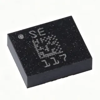
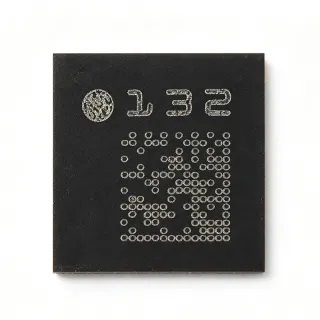
MMA3221EGR2 - ±50g/±20g Dual-Axis Analog Accelerometer | NXP
Référence : MMA3221EGR2 ✗ Fin de vie| Qté | Prix unitaire | Total |
|---|---|---|
| 1 | $18.5 | $18,50 |
| 10 | $16.2 | $162,00 |
| 100 | $13.95 | $1 395,00 |
| 500 | $11.8 | $5 900,00 |
| 1 000 | $9.85 | $9 850,00 |
MMA3221EGR2 Présentation
An accelerometer is a MEMS (micro-electromechanical systems) sensor that converts gravitational or mechanical acceleration into a measurable electrical signal. In the system hierarchy, it sits within motion sensors, which are a subset of inertial measurement units (IMUs) and, more broadly, sensors. Capacitive MEMS accelerometers detect displacement of a proof mass via changes in capacitance between interdigitated comb fingers, then convert that capacitance change into a voltage using on-chip signal conditioning.
Key features of the MMA3221EGR2 include independent full-scale ranges per axis (X: ±50g, Y: ±20g), a 4-pole low-pass filter for noise bandwidth limiting, integrated signal conditioning, and ratiometric analog output. The device operates from a single 5.0 V supply and includes self-test capability and over-range protection. Its robust SOIC-20 package is designed for surface-mount assembly and is well suited to high-vibration environments.
The MMA3221EGR2 uses a silicon capacitive MEMS proof mass with on-chip ASIC signal conditioning. The architecture includes a precision charge integrator, temperature compensation, and a 4-pole active low-pass filter. The ratiometric analog output simplifies ADC interfacing and improves noise immunity in industrial environments. Per the manufacturer datasheet, the device provides stable sensitivity across the -40 °C to +105 °C operating range.
Typical applications include airbag deployment systems and crash detection, vehicle stability control and rollover sensing, industrial vibration monitoring, tilt and inclination sensing in harsh environments, and tilt measurement for heavy machinery. Independent X/Y full-scale ranges allow the X axis to capture high-g crash events while the Y axis measures lower-g rollover events from a single sensor.
When designing with this part, ensure adequate PCB decoupling near the supply pin and use ratiometric ADC conversion to cancel supply noise. Route the analog outputs away from high-current switching traces to preserve signal integrity.
This page synthesizes distributor pricing, drop-in compatible alternatives, and practical design notes not found in the manufacturer datasheet alone.
Alternatives de remplacement direct pour MMA3221EGR2 — même boîtier, compatible broche à broche. Les références à boîtier différent nécessitant une retouche du PCB sont exclues.
Variantes de cette série
Modèles de la même série directement compatibles avec MMA3221EGR2 (même facteur de forme et même empreinte) — différant par Axis, Filter, Operating Temperature, Output Type, Package.
Outil de comparaison rapide — sélectionnez des références alternatives pour une comparaison côte à côte :
MMA3221EG
✅ Remplacement direct📋 Alternative de référence (hors catalogue)
MMA3202EGR2
✅ Remplacement direct📋 Alternative de référence (hors catalogue)
MMA2202D
✅ Remplacement direct✓ En stock
$9.75 / unité
Voir la fiche technique →MMA3221EGR2 Valeurs maximales et caractéristiques électriques
| Type | Accelerometer |
| Axis | X, Y |
| Acceleration Range (X) | ±50 g |
| Acceleration Range (Y) | ±20 g |
| Bandwidth | 400 Hz |
| Type de sortie | Analog, Ratiometric Voltage |
| Tension d'alimentation | 5.0 V typical (range per datasheet) |
| Température de fonctionnement | -40 °C to +105 °C |
| Boîtier | 20-SOIC (300 mil) |
| Type de montage | Surface Mount |
| Sensor Technology | Capacitive MEMS (silicon micromachined) |
| Filter | 4-pole low-pass (on-chip) |
| Self-Test | Yes |
| Statut RoHS | Compliant |
| Lead Free Status | Lead Free |
Guide de configuration des broches du MMA3221EGR2 20-soic (300 mil)
Configuration des broches du MMA3221EGR2 (boîtier 20-soic (300 mil)). La numérotation des broches, les fonctions et les schémas de connexion sont définis dans la fiche technique du fabricant. Consultez-la pour l'empreinte exacte et les directives de soudage.

Aucune donnée de brochage détaillée disponible pour MMA3221EGR2.
Consultez la fiche technique pour la configuration complète des broches.
Applications typiques
MMA3221EGR2 convient pour 6 applications: Airbag Deployment and Crash Detection, Vehicle Stability Control and Rollover Sensing, Industrial Vibration Monitoring, Tilt and Inclination Sensing in Harsh Environments, Chassis and Suspension Monitoring, Antenna and Platform Stabilization.
Airbag Deployment and Crash Detection
The MMA3221EGR2's asymmetric ±50 g X-axis and ±20 g Y-axis ranges are purpose-built for automotive airbag ECUs. The X axis captures the sharp, high-g deceleration pulse of a frontal or offset crash (typically 30-50 g peak over 15 ms), while the Y axis records the lower-amplitude lateral acceleration that distinguishes rollover events from benign lateral maneuvers. The internal 4-pole 400 Hz low-pass filter removes high-frequency mechanical resonance from the airbag mounting bracket, ensuring the ECU algorithm sees true vehicle kinematics rather than sensor housing noise. A ratiometric analog output simplifies interface to the ECU's 5 V ADC and rejects supply transients during the cranking pulse. Designers must place the IC close to the vehicle's center of gravity and follow the datasheet's PCB layout guidance to avoid PCB strain-induced offset errors during crash events.
Recommandé
Vehicle Stability Control and Rollover Sensing
Electronic Stability Control (ESC) and rollover detection systems rely on a lateral accelerometer to detect skidding or impending rollover. The MMA3221EGR2's Y-axis ±20 g range is well matched to the 0.5-1.0 g lateral accelerations typical of aggressive maneuvers, while the X-axis ±50 g range still captures severe events like a tire blowout at highway speed. The 400 Hz bandwidth supports the 50-100 Hz control loop typical of ESC ECUs without introducing aliasing of structural resonances. Ratiometric output ensures that supply droop during ABS activation does not introduce false lateral-G readings. For production ESC modules, designers typically calibrate the Y-axis zero-g offset at room temperature and rely on the on-chip temperature compensation for the rest of the -40 °C to +105 °C automotive range.
Recommandé
Industrial Vibration Monitoring
Industrial predictive-maintenance systems mount accelerometers on motors, pumps, and bearings to detect imbalance, misalignment, and bearing wear. The MMA3221EGR2's 400 Hz bandwidth covers the 10-300 Hz range where most rotating-machine faults appear, and the dual-axis capability captures both horizontal and vertical vibration from a single mounting point, halving PCB footprint versus two single-axis sensors. The SOIC-20 package is rugged enough for machinery environments when conformal coating is applied. The 5 V ratiometric analog output interfaces directly to industrial 4-20 mA vibration transmitters or PLC analog inputs. Designers should target sensitivity in the 100-200 mV/g range and apply antialiasing at the ADC to extract envelope spectra for bearing-fault detection.
Recommandé
Tilt and Inclination Sensing in Harsh Environments
Heavy-equipment OEMs use tilt sensors for crane tip-over prevention, off-highway vehicle roll warning, and agricultural-machinery slope monitoring. The MMA3221EGR2's wide -40 °C to +105 °C operating range and SOIC-20 package suit outdoor, vibration-loaded environments where ceramic or module accelerometers would be overkill. The dual-axis output enables a single IC to compute pitch and roll angles in real time using atan2(accel_axis / 1g). The ±20 g Y-axis provides margin for vibration-induced spurious readings on construction equipment. For ±90° tilt applications, designers should mount the sensor with its X-axis aligned to the machine's longitudinal axis and use the ratiometric output to feed a 12-bit or higher ADC.
Recommandé
Chassis and Suspension Monitoring
Active suspension and ride-height control ECUs need direct measurement of vertical and lateral chassis acceleration. The MMA3221EGR2's dual-axis capability captures both axes from a single mounting point near each wheel, reducing wiring harness complexity versus discrete single-axis sensors. The 400 Hz bandwidth captures suspension resonances in the 1-10 Hz band while filtering high-frequency road noise. The asymmetric range is appropriate because vertical wheel-hop events can exceed 20 g while lateral events remain below 10 g. Mount the sensor rigidly to the chassis knuckle or control arm and use the on-chip self-test feature periodically to verify sensor integrity without removing the ECU from the vehicle.
Recommandé
Antenna and Platform Stabilization
Mobile satellite-communication antennas, drone gimbals, and stabilized camera platforms use dual-axis accelerometers as part of an inertial stabilization loop. The MMA3221EGR2's small SOIC-20 package and 5 V supply fit easily on a stabilized-platform controller board, and the ±20 g Y-axis range accommodates the high-frequency jitter from drone propeller vibration. The 400 Hz bandwidth is sufficient for 100 Hz outer-loop stabilization control. Combine with a gyroscope for full IMU functionality and use the on-chip self-test to verify sensor health at power-up. Designers should implement mechanical vibration isolation between the sensor and the vibration source to prevent aliasing of structural resonances into the control loop.
Recommandé
Récapitulatif des produits recommandés
Données de référence d'ingénierie pour MMA3221EGR2 — comparaison, recommandations de conception et informations de conformité.
Guide de sélection
Comparaison avec les alternatives
| Paramètre | Ce produit | MMA3221EG | MMA3202EGR2 | MMA2202D |
|---|---|---|---|---|
| Brand | NXP Semiconductors | NXP Semiconductors | NXP Semiconductors | NXP Semiconductors |
| Package | 20-SOIC (300 mil) | 20-SOIC (300 mil) - same | 20-SOIC (300 mil) - same | SOIC-16 - smaller |
| Axis | X, Y | X, Y | X, Y | X only |
| X-axis Range | ±50 g | ±50 g | ±50 g | ±50 g |
| Y-axis Range | ±20 g | ±20 g | ±50 g (symmetric) | N/A (single axis) |
| Output Type | Analog ratiometric | Analog ratiometric | Analog ratiometric | Analog ratiometric |
| Supply Voltage | 5.0 V | 5.0 V | 5.0 V | 5.0 V |
| Self-Test | Yes | Yes | Yes | Yes |
| Lifecycle Status | Obsolete | Obsolete | Obsolete | Obsolete |
Principaux différenciateurs
- Asymmetric per-axis full-scale range (vs MMA3202EGR2)
- On-chip 4-pole low-pass filter (vs MMA2202D)
- Dual-axis from a single SOIC-20 device (vs Two discrete MMA2202D parts)
Notes de conception
Place the MMA3221EGR2 close to the system center-of-gravity and rigidly bolt or solder it to the chassis. Use the manufacturer-recommended land pattern for SOIC-20 (300 mil) and add a 100 nF decoupling capacitor within 5 mm of the VDD pin. Route the analog outputs as differential pairs with a ground guard to reject switching noise from ECU digital logic.
The MMA3221EGR2 outputs a ratiometric analog voltage, so noise on the 5 V supply appears directly on the output. Use a low-noise LDO (such as a TPS7A45xx or equivalent) for the sensor supply and a unity-gain buffer at the ADC input if the ADC is more than 25 mm away. Apply antialiasing at the ADC with a cutoff at or below half the 400 Hz sensor bandwidth to avoid aliasing of high-frequency mechanical noise.
Do not assume the two axes share the same sensitivity - the MMA3221EGR2 has asymmetric X/Y ranges (±50 g vs ±20 g), so each axis must be calibrated independently. Use the on-chip self-test pin during ECU power-on self-test to verify sensor integrity, but account for the self-test response specified in the datasheet (a known offset shift, not a full-range stimulus). Mounting stress from PCB flexure can induce offset errors; use strain-relief features near the sensor mounting holes.
Estimated: at 5 V supply and typical quiescent current of a few mA, the SOIC-20 dissipates well under 50 mW, so junction temperature rise above ambient is negligible (under 2 °C). No heatsink is required. However, thermal gradients across the PCB from adjacent power components can introduce zero-g offset drift; keep high-power dissipation devices at least 20 mm away from the accelerometer.
Informations de conformité
RoHS and lead-free status confirmed via DigiKey product attributes. AEC-Q100 not explicitly listed; this part predates widespread AEC-Q100 certification in NXP datasheets. Reach/halogen/conflict-mineral status not stated in retrieved data - marked unknown.