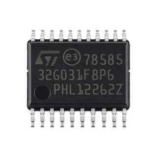
STM8S103F2P3 - 16MHz 8-Bit MCU, 4KB Flash | STMicroelectronics
Référence : STM8S103F2P3 ✓ Actif| Qté | Prix unitaire | Total |
|---|---|---|
| 1 | $0 | $0,00 |
| 10 | $0 | $0,00 |
| 100 | $0 | $0,00 |
| 500 | $0 | $0,00 |
| 1 000 | $0 | $0,00 |
STM8S103F2P3 Présentation
What is an 8-bit microcontroller? An 8-bit MCU is a programmable integrated circuit that executes instructions using an 8-bit data bus. In the embedded-control hierarchy, the STM8S103F2P3 belongs to the STM8S MCU family, which combines a CPU core, Flash program memory, data EEPROM, peripherals, and GPIO in one low-power device. It is intended for applications that need deterministic control and multiple serial interfaces without the resource demand of a higher-bit MCU.
The STM8S103F2P3 is listed by STMicroelectronics as part of the STM8S103F2/x3 access line. The verified specifications show 4 KB of Flash for the STM8S103F2P3 ordering code, while the related STM8S103F2 family also includes variants with larger memory. The device provides a 16 MHz clock, a 10-bit ADC, three timers, UART, SPI, and I2C, making it a broad platform for embedded sensing, communications, and actuator-control designs.
The 20-pin TSSOP package helps reduce PCB area compared with larger leaded packages. With 16 I/O ports, the device can connect digital inputs, outputs, and serial peripherals while leaving the remaining pins for power, clock, reset, and programming functions. The 2.95 V to 5.5 V operating range supports common embedded supply systems, although the final design should verify every electrical limit against the manufacturer datasheet.
Typical applications include small sensor nodes, digital control boards, temperature or analog-signal monitoring, simple communication bridges, LED and relay-control systems, and compact access-line embedded products. The UART, SPI, and I2C peripherals allow the MCU to interface with sensors, transceivers, memories, displays, and actuators without requiring a separate interface controller.
For a new design, verify the exact pinout, alternate-function assignments, clock configuration, and reset behavior before layout. The verified web data does not provide a complete pin-by-pin mapping, pricing, lead time, or all electrical timing values, so those fields are marked as unavailable rather than inferred.
Alternatives de remplacement direct pour STM8S103F2P3 — même boîtier, compatible broche à broche. Les références à boîtier différent nécessitant une retouche du PCB sont exclues.
Variantes de cette série
Modèles de la même série directement compatibles avec STM8S103F2P3 (même facteur de forme et même empreinte) — différant par Package, Core, Data EEPROM, Operating Temperature, ADC.
Outil de comparaison rapide — sélectionnez des références alternatives pour une comparaison côte à côte :
STM8S103F3P3
✅ Remplacement direct📋 Alternative de référence (hors catalogue)
STM8S103F3P6
✅ Remplacement direct✓ En stock
$0.92 / unité
Voir la fiche technique →STM8S003F3P6
✅ Remplacement direct✓ En stock
$0.36 / unité
Voir la fiche technique →STM8S003F3P6TR
✅ Remplacement direct✓ En stock
$0.55 / unité
Voir la fiche technique →STM8S103F2P3
✅ Remplacement direct✓ En stock
Contactez-nous pour le prix
Voir la fiche technique →STM8S103F2P3 Valeurs maximales et caractéristiques électriques
| Product Type | 8-bit microcontroller |
| Series | STM8S access line |
| Maximum Clock Speed | 16 MHz |
| Flash Program Memory | 4 KB for STM8S103F2P3 |
| Program Memory Organization | 4K x 8 bits |
| Data EEPROM | Integrated true data EEPROM |
| Supply Voltage Range | 2.95 V to 5.5 V |
| I/O Ports | 16 ports |
| ADC | 10-bit ADC |
| Timer Count | 3 timers |
| UART | Available |
| SPI | Available |
| I2C | Available |
| Boîtier | 20-pin TSSOP |
| Type de montage | Surface mount |
| Architecture | STM8 8-bit MCU |
| Statut du cycle de vie | Active |
Guide de configuration des broches du STM8S103F2P3 20-pin tssop
Configuration des broches du STM8S103F2P3 (boîtier 20-pin tssop). Ce circuit intégré numérique comprend des GPIO, des interfaces de communication (UART, SPI, I2C) et des broches d'alimentation. Consultez la fiche technique du fabricant pour les fonctions alternatives des broches et les options de configuration. Indispensable pour la conception de systèmes embarqués et la conception de circuits imprimés.

Aucune donnée de brochage détaillée disponible pour STM8S103F2P3.
Consultez la fiche technique pour la configuration complète des broches.
Applications typiques
STM8S103F2P3 convient pour 6 applications: Compact Sensor Node, Industrial Control Board, UART Communication Bridge, Digital Control and Relay Board, Simple Analog Monitoring System, LED and Display Controller.
Compact Sensor Node
The STM8S103F2P3 fits compact sensor nodes because it combines a 16 MHz 8-bit MCU, integrated data EEPROM, a 10-bit ADC, and I2C or SPI in a 20-pin TSSOP. The device can sample an analog sensor, store configuration data internally, and update a small display or actuator without a separate memory controller. I2C supports compatible sensors and digital peripherals, while SPI is useful for higher-throughput sensor or storage connections. The main design constraint is the verified 4 KB Flash capacity: firmware must be budgeted carefully, and the exact ADC channels and pin multiplexing must be confirmed from the manufacturer datasheet before assigning external circuitry.
Recommandé
Industrial Control Board
STM8S103F2P3 is suitable for small industrial-control boards where deterministic digital control, serial connectivity, and analog monitoring are needed in a compact package. Its three timers can support timing and periodic control functions, the 10-bit ADC can monitor a conditioned analog signal, and UART or SPI can connect to a downstream controller or sensor. The 2.95 V to 5.5 V supply range aligns with many embedded industrial rails, but the verified data does not provide EMC, isolation, temperature, or protection ratings. Engineers should therefore add appropriate input protection and verify operating limits from the manufacturer documentation rather than assume industrial qualification.
Recommandé
UART Communication Bridge
The STM8S103F2P3 can serve as a small UART-based bridge between a local embedded system and a host computer or peripheral. Its 16 MHz clock provides a practical control platform, while UART handles asynchronous serial communication and the integrated ADC can monitor a local analog input or status signal. The device's compact TSSOP package helps reduce board area in cable-management or instrumentation products. Firmware and external transceiver selection remain critical because the verified data does not specify UART electrical levels, baud-rate limits, or I/O drive strength. A logic-level or RS-232 interface must be selected only after checking the exact pinout and electrical characteristics.
Recommandé
Digital Control and Relay Board
STM8S103F2P3 can control a small digital output board using its GPIO ports, timers, and serial configuration interface. Timers provide a basis for debouncing, periodic updates, or timing sequences, while UART or I2C can accept configuration commands from another controller. The 20-pin TSSOP package leaves the design compact, but the verified data does not provide absolute output-current, voltage, or thermal ratings. Relay or load drivers must therefore be sized independently, with suitable transistor, diode, isolation, and protection components. Verify every output pin and its alternate-function conflict against the manufacturer pinout before final PCB routing.
Recommandé
Simple Analog Monitoring System
The integrated 10-bit ADC makes STM8S103F2P3 appropriate for small analog-monitoring products that must digitize sensor outputs, apply thresholds, and report status. A conditioned analog signal can be sampled locally, while EEPROM can retain calibration or configuration information and UART or I2C can expose results to a host or display. The 16 MHz clock supports responsive control-loop timing, although the verified material does not specify ADC resolution timing, input impedance, reference accuracy, or sampling rate. Those details must be obtained from the manufacturer datasheet, and the analog front end should be designed for the actual sensor output and required measurement bandwidth.
Recommandé
LED and Display Controller
STM8S103F2P3 can coordinate LED indicators, small displays, and periodic status functions in compact control panels. Its GPIO and timer resources support timing and output updates, while I2C or SPI can connect to compatible display or storage devices. The low-voltage operation and compact package help when board space is constrained. However, the verified data does not identify dedicated display drivers, LED current limits, or absolute maximum output ratings. Use external driver circuits when required and confirm all port mappings and peripheral ownership in the manufacturer datasheet. This makes the MCU suitable for low-power human-interface or indicator boards when external electrical protection is designed in.
Recommandé
Récapitulatif des produits recommandés
Données de référence d'ingénierie pour STM8S103F2P3 — comparaison, recommandations de conception et informations de conformité.
Guide de sélection
Comparaison avec les alternatives
| Paramètre | Ce produit | STM8S103F3P3 | STM8S103F3P6 | STM8S003F3P6 | STM8S003F3P6TR |
|---|---|---|---|---|---|
| Package | 20-pin TSSOP | 20-pin TSSOP | 20-pin TSSOP | 20-pin TSSOP | 20-pin TSSOP |
| Brand | STMicroelectronics | STMicroelectronics | STMicroelectronics | STMicroelectronics | STMicroelectronics |
Principaux différenciateurs
- Verified 16 MHz access-line MCU with integrated data EEPROM (vs STM8S003F3P6)
- Verified 4 KB Flash for the exact target ordering code (vs STM8S103F3P3)
- 20-pin TSSOP package with mixed serial connectivity (vs STM8S103F3P6)
Notes de conception
Route the MCU power pins and decoupling structure directly according to the manufacturer recommended layout. Because the verified data does not include the complete pinout or capacitor recommendations, do not select capacitor values or assign pins from family-name assumptions. Confirm the STM8S103F2P3 TSSOP symbol, power pins, reset connection, clock path, programming access, and exposed thermal or exposed-pad details from the STMicroelectronics datasheet before release.
Treat the 4 KB Flash figure as an exact constraint for this ordering code. Related STM8S103F2-family devices may have more memory, so using a generic family linker setting can produce an image that does not fit. Check the selected device identifier in the development tool, review the memory map, and budget bootloader and application space separately. Also verify that any alternative has identical programming, reset, interrupt, and peripheral behavior rather than relying on package appearance alone.
Keep I2C and SPI routing short and controlled, especially when the MCU is used with external sensors or memory. The verified data confirms the availability of UART, SPI, and I2C but does not provide detailed rise-time, capacitance, or timing limits, so pull-up values and bus topology must be derived from the selected peripheral devices and the manufacturer electrical tables. Keep analog and digital paths separated where practical, and provide local return paths beneath high-speed or switching circuitry.
Design the supply rail for the verified 2.95 V to 5.5 V STM8S103F2P3 operating range, including startup and peripheral load behavior. The verified sources do not state current consumption, output-drive limits, or absolute maximum ratings, so those values must be obtained from the manufacturer datasheet before choosing regulators or estimating thermal dissipation. Use external protection and sequencing only after verifying the device's reset and power-on requirements.
Informations de conformité
The supplied verified data identifies the device as active and lists it as an STMicroelectronics 8-bit MCU, but it does not provide RoHS, REACH, AEC-Q100, lead-free, halogen-free, or conflict-minerals statements.