מעגלי ממשק
תת-קטגוריות
מוצרים (2,300+)

TCA9517DGKR - I2C Bus Repeater Level Translator | TI
The Texas Instruments TCA9517DGKR is a 2-channel, bidirectional level-translating I2C bus repeater and buffer supporting 400 kHz (Fast-mode) I2C and SMBus operation, with A-side supply from 0.9 V to 5.5 V and B-side supply from 2.7 V to 5.5 V, housed in an 8-pin VSSOP (DGK) package. A level-translating I2C bus buffer is an interface IC that sits between two segments of an I2C or SMBus, electrically isolating the bus capacitance and logic levels on each side. In the interface IC hierarchy, it belongs to the signal buffer/repeater family of level translators, which sit above simple transistors and below full protocol bridges. By segmenting the bus, the repeater allows longer buses and more devices than the I2C standard capacitance limit would otherwise permit. Key features include support for both standard-mode (100 kHz) and fast-mode (400 kHz) I2C signaling, an enable (EN) pin for bus isolation and power sequencing, and powered-off high-impedance I2C pins that effectively remove the device from the bus when either supply is absent. The TCA9517 also incorporates an acceleration feature that speeds up the rising edge of SDA and SCL on the B side. Architecturally, the TCA9517 uses two distinct driver types. The A-side drivers operate from 0.9 V to 5.5 V and drive more current without requiring the buffered-low static offset voltage, so a low on the B side translates to a nearly 0 V hard low on the A side. This accommodates the smaller voltage swings of lower-voltage logic such as 1.2 V or 1.8 V I2C peripherals. The B side retains the static voltage offset needed for hot-swapping and rise-time acceleration. Typical applications include I2C bus expansion in industrial automation, server and telecom backplane management (SMBus), and level translation between 1.8 V microcontrollers and 3.3 V sensors or EEPROMs. Design consideration: the A-side output can sink more current than a plain MOSFET translator, so pay attention to total bus capacitance per segment; keep pull-up resistor values sized per segment rather than one pair for the whole bus. This page synthesizes distributor pricing, verified drop-in alternatives, and practical design notes not found in the manufacturer datasheet alone.

TCA9517DGKRQ1 - Automotive I2C Level-Shifting Buffer | TI
The Texas Instruments TCA9517DGKRQ1 is an automotive-grade, 2-bit level-translating I2C/SMBus buffer/repeater operating at up to 400 kHz, housed in an 8-pin VSSOP (DGK) package and qualified to AEC-Q100 for -40C to +125C operation. An I2C bus buffer, also called a level translator or bus repeater, is an interface IC that sits between two segments of an I2C or SMBus serial bus. Its role in the interface IC hierarchy is to isolate bus capacitance, allowing longer or more heavily loaded buses, and to translate logic voltage levels between devices powered from different supply rails, such as a 1.8V microcontroller talking to 5V peripherals. Key features include bidirectional voltage-level translation between low voltages down to 0.9 V on side A and 2.7 V to 5.25 V on side B, support for both standard-mode (100 kHz) and fast-mode (400 kHz) I2C plus SMBus, and a powered-off high-impedance state that isolates both bus segments when either supply rail is absent. The enable (EN) pin provides additional bus control, and open-drain I/O structures preserve the wired-AND nature of I2C. Technically, the TCA9517-Q1 drives both sides of the bus, refreshing rise times and removing the cumulative load of stubs and cables. Unlike passive FET level shifters, it does not trade drive strength for level translation, so clock stretching and multi-master arbitration are preserved. It supports up-translation, down-translation, and same-level buffering. Typical applications include automotive body electronics and infotainment I2C bus extension, PMBus/SMBus power-supply management in industrial systems, and level translation between 1.8V or 3.3V MCUs and 5V sensors or EEPROMs. Design consideration: because the device drives each side actively, do not connect the A and B sides to the same bus segment, and keep EN tied low until both supply rails are stable to avoid bus latch-up during power sequencing. This page synthesizes distributor pricing, drop-in alternatives, pinout data, and practical design notes not found in the manufacturer datasheet alone. Pricing shown as of 2026-10-19.

TCA9517DR - Level-Shifting I2C Bus Repeater | Texas Instruments
The Texas Instruments TCA9517DR is a 2-bit level-translating I2C/SMBus bus buffer supporting 400 kHz Fast Mode operation, with an A-side supply range of 0.9 V to 5.5 V and a B-side supply range of 3.0 V to 5.5 V, housed in an 8-pin SOIC (D) package. An I2C bus buffer (also called a bus repeater or level translator) is an interface IC that sits between two segments of an I2C or SMBus serial bus. Its role in the interface IC hierarchy is to electrically isolate the two segments while translating signal levels between devices powered at different voltages, allowing low-voltage microcontrollers to communicate safely with higher-voltage peripherals. A buffer also isolates bus capacitance, so each side can drive longer traces or more devices than a single unbuffered bus would allow. Key features include fully bidirectional level translation with no direction-control pin, a low-level input on the A-side set at 0.3 x VCCA that accommodates smaller voltage swings of lower-voltage logic, and a powered-off high-impedance state on all pins so the part never loads the bus when unpowered. According to the TCA9517 datasheet, the A-side drivers operate from 0.9 V to 5.5 V, drive more current than B-side drivers, and do not require a buffered low or static offset voltage, producing a nearly 0 V hard low on the A-side. Architecturally, the TCA9517 uses open-drain drivers with rise-time support rather than a static 0.5 V low offset on the A-side, distinguishing it from the older PCA9517 generation. The 230 ns maximum propagation delay preserves I2C Fast Mode timing margins at 400 kHz, and the two channels translate both SDA and SCA lines simultaneously. Typical applications include connecting 1.8 V or 3.3 V MCU I2C ports to 5 V EEPROMs, sensors, and RTCs in industrial and telecom equipment, isolating bus capacitance in long backplane runs, and buffering densely loaded SMBus segments. Design consideration: keep the A-side connected to the lower-voltage, higher-capacitance segment; the B-side static 0.5 V offset requires pairing buffers B-side to A-side in cascaded topologies. This page synthesizes distributor pricing, verified drop-in alternatives, pinout, and practical design notes not found in the manufacturer datasheet.
TCA9536-Q1 - 4-Bit I2C/SMBus I/O Expander AEC-Q100 | TI
The Texas Instruments TCA9536-Q1 is a 4-bit remote I/O expander for the I2C bus and SMBus with configuration registers, operating from a 1.65V to 5.5V supply in an 8-pin X2SON package measuring just 1.35 mm x 0.8 mm. It provides general-purpose remote I/O expansion for most microcontroller families via the I2C interface and is AEC-Q100 qualified for automotive applications. An I/O expander is an interface IC that extends the number of general-purpose input/output (GPIO) pins of a microcontroller or system controller through a serial bus such as I2C or SMBus. In the hierarchy of embedded system components, the I/O expander sits within the interface IC family, alongside level translators, bus buffers, and serial transceivers, and functions as a remote GPIO peripheral for system masters that need additional discrete control or monitoring lines without adding a larger microcontroller. Key features of the TCA9536-Q1 include 4 configurable I/O pins that can be individually programmed as inputs or outputs through a 4-bit Configuration register, an Input Port register for reading pin states, an Output Port register for driving pins, and a Polarity Inversion register for active-HIGH or active-LOW operation. The device supports fast-mode I2C bus operation up to 1 MHz, uses only two bus lines (SDA and SCL), and operates across the wide 1.65V to 5.5V VCC range for compatibility with 1.8V, 2.5V, 3.3V, and 5V logic systems. The architecture implements four 4-bit registers (Configuration, Input Port, Output Port, and Polarity Inversion) accessible over the serial bus, with power-on reset defaulting all pins to inputs. Because the TCA9536-Q1 register map follows the widely deployed PCA9536 register convention, the same software drivers used for PCA9536-class expanders generally work unchanged, simplifying migration and second-sourcing within an existing firmware stack. Typical applications include automotive body-control modules, GPIO expansion in space-constrained sensor nodes, keypad or switch monitoring, LED and relay control through external drivers, and power-rail sequencing enables in infotainment and cluster displays. Its tiny X2SON footprint makes it especially attractive where board area is the limiting factor. Design consideration: because the X2SON package places multiple pins on very fine pitch beneath the die, follow TI's recommended PCB land pattern exactly, including via-in-pad thermal relief, and verify solderability with the correct reflow profile for the Q1 automotive grade. This page synthesizes verified distributor data, drop-in alternative analysis, and practical design guidance that goes beyond the raw datasheet parameters.

TCA9544APWR - 4-Ch I2C/SMBus Mux with Interrupt | TI
The Texas Instruments TCA9544APWR is a low-voltage 4-channel bidirectional translating I2C and SMBus multiplexer with interrupt logic, operating from 1.65 V to 5.5 V and supporting both Standard-Mode (100 kHz) and Fast-Mode (400 kHz) bus speeds, housed in a 20-pin TSSOP (PW) package. An I2C multiplexer (bus switch) is an interface IC that lets a single master SCL/SDA pair be shared among multiple downstream I2C buses. It sits in the interface IC hierarchy between the bus transceiver level and full protocol bridges: multiplexer -> I2C switch -> I2C/SMBus interface -> system bus management. Its core role is resolving slave address conflicts and providing voltage translation between buses that run at different logic levels. Key features include four independently selectable SCn/SDn channel pairs controlled by a single 8-bit control register, integrated interrupt logic with four downstream interrupt inputs (INT0-INT3) and one open-drain master-side INT output, and a 3-bit address-select input (A0-A2) that places the device at one of eight I2C addresses for multi-mux systems. Pass-gate switch architecture enables true bidirectional translation between 1.65 V, 2.3 V, 3.3 V and 5 V buses without direction pins. Technically, the device passes the upstream SCL/SDA pair to any single channel or combination of channels determined by the control register, which is written and readable via I2C. Because it is a passive pass-gate (not a buffered repeater), it adds minimal propagation delay but does not regenerate signal rise times, so total bus capacitance limits remain applicable. Typical applications include resolving address conflicts between multiple identical sensors (temperature, accelerometers) on one controller, isolating capacitive loading in long or heavily populated I2C segments, and fan-out from an SMBus host in servers and industrial controllers. Design consideration: because the pass-gate does not buffer, keep total downstream capacitance within the 400 pF I2C Fast-Mode limit; series resistance of the switch slightly increases rise times, so verify pull-up sizing at 400 kHz. This page synthesizes distributor pricing, drop-in alternatives, and practical design notes not found in the manufacturer datasheet.
TCA9548ADGSR - 8-Channel 1.65-5.5V I2C Switch | TI
The Texas Instruments TCA9548ADGSR is a low-voltage 8-channel I2C/SMBus switch with reset, operating from a 1.65V to 5.5V supply and housed in a 24-pin VSSOP (DGS) package. It resolves I2C slave address conflicts by multiplexing one upstream SDA/SCL pair to any combination of eight downstream bus channels, selected through the I2C bus itself. An I2C switch (also called an I2C multiplexer or bus switch) is a signal-switching IC in the interface IC family that sits between a system controller and multiple I2C targets. In the hierarchy of I2C bus management devices, it sits alongside bus buffers, level translators, and I/O expanders, and its core job is to let a controller with one or two address pins reach many devices that would otherwise clash on identical addresses. Key features of the TCA9548A include an active-low RESET input that recovers a hung downstream bus without cycling power, three address pins (A0, A1, A2) that allow up to eight TCA9548A devices on one I2C bus, and pass-gate switches with low ON resistance. Power-up deselect of all channels guarantees a glitch-free, deterministic bus state at startup, and the device is I2C Bus and SMBus compatible. A major architectural advantage is built-in voltage translation: because the pass-gate switches are powered from VCC, the device allows 1.8V, 2.5V, 3.3V, and 5V bus domains to coexist across the same multiplexer, eliminating a separate level shifter in mixed-voltage systems. Hot insertion is also supported, so a downstream card can be connected without disturbing the upstream bus. Typical applications include sensor hubs with multiple identical-address sensors, LCD and OLED display control via I2C, server backplanes and fans trays, and battery-management or power-supply modules where a controller must isolate and poll many buses. Selecting channels in any combination lets a controller scan multiple buses without repeated I2C re-addressing. Design consideration: keep RESET asserted through a controller GPIO at power-up, and add a pull-up so the device does not float into an undefined state; channel selection is a single register write, so bus turnaround overhead is minimal. This page synthesizes distributor pricing, drop-in alternative analysis, application guidance, and design notes beyond what the manufacturer datasheet alone provides.

TCA9548APWR - 8-Channel I2C Switch with Reset | Texas Instruments
The Texas Instruments TCA9548APWR is a low-voltage 8-channel I2C/SMBus switch with reset and voltage translation, packaged in a 24-pin TSSOP (PW). It operates from 1.65V to 5.5V and allows an upstream I2C bus to fan out to eight downstream channels, each selectable in any combination via the I2C bus. The device features an active-low reset input, three address pins (allowing up to eight devices on the bus), and low ON-state resistance switches. An I2C switch is a specialized multiplexer that enables a single I2C master to communicate with multiple slave devices that share the same address or operate at different voltage levels. By isolating downstream buses, it prevents address conflicts and allows voltage translation between the upstream and downstream segments. The TCA9548A belongs to the family of I2C bus switches and multiplexers, which are essential in complex systems where multiple sensors, EEPROMs, or other I2C peripherals need to be managed. Key features include bidirectional translating switches, I2C and SMBus compatibility, active-low reset, three address pins, channel selection via I2C in any combination, power-up with all channels deselected, and low RON switches. The device supports a wide supply voltage range of 1.65V to 5.5V, making it suitable for mixed-voltage systems. The operating temperature range is -40°C to 85°C, and the package is a 24-pin TSSOP (PW) with a body size of 7.8mm x 4.4mm. Technically, the TCA9548A uses a pass-gate architecture that provides bidirectional voltage translation. The VCC pin must be connected to the lowest voltage used on the bus to ensure proper level shifting. The device has a low quiescent current and supports standard and fast I2C modes. The reset input allows the switch to be reset to its default state (all channels deselected) without power cycling. Typical applications include server and telecom systems for managing multiple I2C devices, industrial control for sensor arrays, and consumer electronics for connecting multiple peripherals. The TCA9548A is also used in automotive infotainment and ADAS systems where multiple I2C buses need to be isolated. When designing with this device, ensure that the VCC pin is at the lowest voltage of any bus segment to guarantee correct voltage translation. Also, consider the capacitive loading on each channel and use appropriate pull-up resistors for the I2C bus.

TCA9555PWR - 16-bit I2C/SMBus I/O Expander w/ Interrupt | TI
The Texas Instruments TCA9555PWR is a 16-bit I2C/SMBus I/O expander with interrupt output and configuration registers, operating from 1.65 V to 5.5 V VCC and housed in a 24-pin TSSOP (PW) package. It provides remote 16-bit general-purpose parallel I/O expansion through the two-line bidirectional I2C bus and supports SMBus signaling up to 400 kHz in the TI variant (with 1 MHz capability in the UMW second-source marking). The device integrates three hardware address pins (A0/A1/A2), an open-drain active-low INT output, and per-port weak pull-up resistors that can be enabled via the configuration register. An I2C I/O expander is a category of bus-interface IC that allows a host microcontroller with limited native GPIO to gain additional digital inputs or outputs over a two-wire serial bus. The taxonomy is: I/O expander -> parallel I/O -> digital interface IC -> interface IC -> integrated circuit. The TCA9555 belongs to the second-generation TI family characterized by wider VCC range (down to 1.65 V), higher SMBus speed, lower standby current, and the addition of weak pull-ups. It is widely used to recover GPIO budget on small-pin-count MCUs, add level-translated interfaces, and aggregate slow peripherals such as keypads, LEDs, or push-buttons. Key features of the TCA9555PWR include 16 individually configurable I/O bits, 5 V tolerant I/O ports, 25 mA sink/source per bit (with total package limits), an active-low interrupt line that fires on any input state change, and three programmable I2C address pins supporting up to eight devices on the same bus (64 I/O total). The internal power-on reset brings all I/O to inputs and clears the configuration, polarity-inversion, and mask registers to defaults, eliminating spurious writes at startup. The architecture is a CMOS parallel expansion core driven by a finite state machine on the I2C/SMBus interface. Writes go through a write-protection check and into 8-bit configuration, polarity, and output registers; reads decode the input and output registers with optional polarity inversion. Hardware behavior is fully static and register-mapped, so no clock is required externally. Typical applications include MCU GPIO expansion in industrial control panels, signal aggregation in telecom baseband cards, keypad/LED scanning, and portable consumer devices such as e-readers where any-pin-as-input is needed for button wake events. A representative circuit places the TCA9555PWR on the host's I2C bus with 4.7 kohm pull-ups on SDA/SCL, bypassed VCC, and optional 10 kohm pull-ups on the interrupt and reset pins. INT can be wired to the MCU's edge-sensitive external interrupt so the host wakes only when an input state changes, saving overall system power. When designing with this device, confirm VCC level compatibility - the 1.65 V lower bound matches low-voltage MCUs, but the host and the device must share a common reference. Allow total DC current budget per bank and per package; aggregate sink/source must be derated for high-bit-count use. Use the configuration register to enable or disable weak pull-ups based on the external pull-up strength present on the line.
TCA9617BDGKR - 1MHz FM+ I2C Bus Repeater, VSSOP-8 | Texas Instruments
The Texas Instruments TCA9617BDGKR is a 2-bit bidirectional I2C/SMBus buffer and repeater that performs voltage level translation between mixed-voltage buses in a single 8-pin VSSOP (DGK) package. It supports I2C Standard-mode, Fast-mode, and Fast-mode Plus (Fm+) operation up to 1 MHz, and translates bidirectionally between a low-voltage A-side bus (0.8 V to 5.5 V) and a high-voltage B-side bus (2.2 V to 5.5 V), enabling seamless interconnect between legacy 3.3 V/5 V microcontrollers and modern low-voltage processors operating at 1.0 V, 1.2 V, or 1.8 V rails. An I2C bus repeater is a specialized bus interface device that electrically isolates two physical I2C segments while still allowing them to behave as one logical bus. By buffering the SCL and SDA lines, a repeater overcomes the classic I2C limitation of bus capacitance: each segment of the bus is loaded independently, so engineers can attach far more devices, run longer PCB traces, or use longer cables than would otherwise be possible. The TCA9617B also performs voltage level translation (also called a level shifter), so the same repeater allows a low-voltage MCU to talk to a 5 V sensor without dedicated glue logic. Key specifications of the TCA9617BDGKR include: 1 MHz maximum clock frequency, support for 0.8 V to 5.5 V on the A-side, 2.2 V to 5.5 V on the B-side, EN (enable) input with powered-off high-impedance behavior, low standby current (VCCA suspend), and integrated pull-up current sources that eliminate the need for external bus pull-ups on the B-side. The BiCMOS internal design provides clean edges and controlled rise/fall times even at full Fm+ speed. The device is offered in three temperature grades with -40 °C to +85 °C as the commercial grade. Typical applications include I2C bus extension between boards, voltage translation between low-voltage MCUs and 3.3 V/5 V peripherals, server backplanes, telecommunications equipment, and any system where the total bus capacitance exceeds the 400 pF Fast-mode or 550 pF Fast-mode Plus limit imposed by the I2C specification. The repeater transparently regenerates SCL and SDA so that slaves on either side see a clean, well-formed waveform. When designing with the TCA9617B, observe that the A-side and B-side each require their own pull-up resistors; the B-side pull-ups must be to VCCB and the A-side pull-ups must be to VCCA. Avoid enabling the device with EN high before both VCCA and VCCB rails have ramped. Series resistance on the bus should be kept low to preserve Fm+ rise-time margins. This page synthesizes distributor pricing, drop-in alternatives, and practical design notes not found in the manufacturer datasheet, providing a single reference for engineers selecting an I2C repeater/level shifter for mixed-voltage systems.
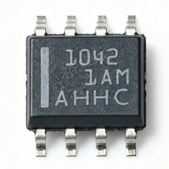
TCAN1042GVDRQ1 - Automotive CAN FD Transceiver | Texas Instruments
TCAN1042GVDRQ1 is an automotive fault-protected CAN transceiver from Texas Instruments, supporting CAN FD data rates up to 5 Mbps with I/O level shifting. It is housed in an 8-pin SOIC (D) package and operates across a temperature range of -55°C to 125°C. A CAN transceiver is a physical layer interface between a CAN controller and the CAN bus twisted-pair wiring. It converts the differential CAN bus signals (CANH/CANL) into single-ended logic levels for the controller, and vice versa. In automotive and industrial networks, the transceiver must handle harsh electrical environments, including voltage transients, ground offsets, and short-circuit conditions, all of which TCAN1042GVDRQ1 is designed to protect against. Key features include fault protection against bus short-circuits and high-voltage transients, I/O level shifting for interfacing with 3.3V or 5V controllers, flexible data-rate operation up to 5 Mbps, and low-power standby mode. The device meets the requirements of ISO 11898-2 for automotive CAN, providing robust communication with a 1/1 driver/receiver configuration and half-duplex operation. Technically, TCAN1042GVDRQ1 integrates a differential driver and receiver, providing differential transmit and receive capability. The I/O level shifting feature allows direct connection to microcontrollers with lower logic levels, eliminating the need for external level translators. Fault protection safeguards the device and bus against short circuits, thermal stress, and voltage surges, ensuring reliable communication in noisy environments. Typical applications include automotive body control modules, gateways, battery management systems, industrial automation, and medical devices where reliable CAN communication is required. The wide operating temperature range and AEC-Q100 qualification (implied by automotive designation) make it suitable for under-hood and harsh environment deployments. During design, ensure proper decoupling capacitors (100 nF and 10 uF) are placed close to the VCC pin to minimize noise, and use the appropriate bus termination resistors (120 ohms) at both ends of the bus. The SOIC-8 package allows compact PCB layouts, but thermal management should be considered for high-temperature environments.
TCAN1044DRQ1 - 8Mbps CAN FD Transceiver, 8-SOIC | Texas Instruments
The Texas Instruments TCAN1044DRQ1 is an automotive-qualified, high-speed Controller Area Network (CAN) transceiver meeting the physical-layer requirements of the ISO 11898-2:2016 standard. It supports both classical CAN and CAN FD (Flexible Data-Rate) networks at data rates up to 8 megabits per second (Mbps), and ships in an 8-pin SOIC (DRB) package with an operating temperature range of -40 C to +125 C. A CAN transceiver is a physical-layer interface IC that bridges a digital CAN protocol controller (typically embedded in a microcontroller) to a differential two-wire CAN bus. The transceiver translates the controller's single-ended TXD/RXD logic signals to the bus's dominant/recessive differential signaling required by ISO 11898-2, while providing bus-side ESD protection, common-mode range, and dominant-time-out fault protection. The TCAN1044-Q1 family sits in the CAN interface IC -> interface IC -> integrated circuit hierarchy and is a foundational building block for in-vehicle networks (IVN). Key features include 8 Mbps CAN FD data-rate support for next-generation vehicle networks, IEC 61000-4-2 ESD protection on bus pins, low-loop delay for propagation-tight networks, and a low-power standby mode with a remote-wake-up wake request via the bus (per the TCAN1044 family datasheet). The device operates from a single 4.5 V to 5.5 V VCC supply, draws typically 50 mA in normal mode, and integrates thermal shutdown plus bus-dominant time-out to prevent network lockup. The TCAN1044DRQ1 architecture uses a high-speed differential driver and a wide-common-mode receiver that exceeds the -2 V to +7 V common-mode range required by ISO 11898-2:2016. Internal level shifting on TXD/RXD allows direct connection to 3.3 V or 5 V microcontrollers without external logic-level translators, and the integrated bus fault protection tolerates -58 V to +58 V transients common in automotive 12 V/24 V systems. Typical applications include automotive body and chassis CAN nodes (BCM, gateway modules), CAN FD powertrain networks, industrial CAN-bus field-bus nodes, and electric-vehicle battery management system (BMS) master/slave communication. The AEC-Q100 Grade 1 qualification makes it appropriate for under-hood and safety-critical vehicle ECUs. When designing with this part, observe the 60 ohm bus termination requirement of ISO 11898-2 and place a 100 nF VCC decoupling capacitor within 2 mm of the supply pin. Avoid routing the CANH/CANL differential pair over splits in reference planes, and use a 120 ohm characteristic-impedance cable/trace geometry. This page synthesizes distributor pricing, drop-in pin-compatible alternatives, and practical PCB design notes for the TCAN1044DRQ1 - information not consolidated in the manufacturer datasheet alone.

TCAN1051-Q1 - Automotive Fault-Protected CAN FD Transceiver | Texas Instruments
TCAN1051-Q1 from Texas Instruments is an automotive fault-protected CAN transceiver with flexible data-rate and sleep mode, meeting ISO 11898-2 (2016) High-Speed CAN physical layer standard. It comes in an 8-pin SOIC package, supporting data rates up to 2 Mbps in CAN FD networks; variants with the G suffix support up to 5 Mbps, while V-suffix versions add a secondary power supply input for I/O voltage. A CAN transceiver is the physical-layer interface between a CAN protocol controller (MCU) and the two-wire differential CAN bus. In the automotive hierarchy, the CAN bus connects ECUs such as engine control, body control, and infotainment modules. The transceiver converts TXD/RXD logic signals from the MCU into differential CANH/CANL signals on the bus and provides bus fault protection. Key features include high on-chip IEC ESD protection, silent mode for reduced power consumption, and AEC-Q100 automotive qualification. The device is designed for harsh automotive environments, with fault protection that withstands bus transients. The flexible data-rate option enables CAN FD networks up to 5 Mbps, making it suitable for modern vehicle architectures that require higher bandwidth. The TCAN1051 family uses a robust physical-layer design with protection diodes and a dominant time-out function, ensuring reliability under bus shorts and high-voltage transients. The device supports both 5 V and (in V variants) 3.3 V I/O reference voltage, allowing direct interface with low-voltage microcontrollers. Typical applications include automotive body control modules, battery management systems, powertrain control, and industrial automation networks. The TCAN1051-Q1 is also widely used in diagnostics (OBD-II) and infotainment systems. Design consideration: ensure proper termination (120 ohm) and place TVS diodes and bus filtering capacitors close to the on-board connectors to prevent transient events from propagating into the PCB.
TCAN1051DRBRQ1 - Automotive CAN FD Transceiver | TI
The Texas Instruments TCAN1051DRBRQ1 is an automotive fault-protected CAN transceiver with CAN FD flexible data-rate support up to 2 Mbps, integrated sleep mode, and a 5 V supply, housed in an 8-pin VSON (DRB) 3x3 mm package rated from -55C to +125C. A CAN (Controller Area Network) transceiver is the physical-layer interface IC that converts the logic-level TXD and RXD signals of a CAN controller into the differential CANH and CANL bus signals defined by ISO 11898. Within the vehicle networking hierarchy, the transceiver sits between the MCU/CAN controller and the twisted-pair bus, providing dominant/recessive signaling, bus fault protection, and low-power standby or sleep behavior for networked electronic control units. Key features include automotive AEC-Q100 qualification, fault protection on the CAN bus pins (protection against faults to battery, ground, and overvoltage per the TI TCAN1051-Q1 product page), CAN FD flexible data-rate support up to 2 Mbps, and a sleep mode that reduces quiescent current for always-on vehicle networks. The -55C to +125C operating range supports under-hood and chassis deployments. The device implements a half-duplex differential physical layer with integrated receiver and driver stages. Internal protection circuitry clamps bus-pin transients and survives DC fault conditions on CANH and CANL, reducing the need for extensive external TVS components in harsh 12 V and 24 V vehicle power environments. Typical applications include body control modules, gateways, ADAS sensor clusters, battery management systems, and industrial CAN networks requiring robust fault tolerance and low standby power. Design consideration: confirm the sleep-mode wake behavior and bus biasing scheme against the TI datasheet, and verify that the 3x3 mm VSON thermal pad is well soldered to ground for transient robustness. This page synthesizes verified distributor listings, drop-in same-family alternatives, and design guidance not consolidated in the manufacturer datasheet.

TCAN1145DRQ1 - Automotive CAN FD Transceiver | Texas Instruments
The Texas Instruments TCAN1145DRQ1 is an automotive CAN FD transceiver with selective wake and SPI-configurable operation, supporting data rates up to 5 Mbps and processor I/O voltages from 1.8 V to 5 V in a 14-pin SOIC package. It is designed for high-speed CAN networks that need enhanced data rates, reduced-node sleep operation, and controlled low-power wake behavior. A CAN transceiver is the physical-layer interface between a host processor and a Controller Area Network bus. The TCAN1145-Q1 family supports enhanced high-speed CAN FD and high-speed CAN operation, while its selective-wake function uses wake-up frame identification to reduce the number of active network nodes. Its SPI interface provides access to device configuration and status functions, allowing a microcontroller to manage transceiver behavior without relying on undisclosed control assumptions. The principal verified feature set includes support for CAN FD data rates up to 5 Mbps, nominal processor I/O operation from 1.8 V to 5 V, and selective wake for partial networking. The TCAN1145DRQ1 ordering variant is identified by DigiKey as a 1/1 half-CANbus transceiver in a 14-SOIC package. The TI product description also associates the device with automotive CAN FD applications and ISO 11898-2:2016-compatible selective-wake functionality. The device is intended for vehicle body, comfort, infotainment, gateway, and distributed control networks where sleeping nodes must be awakened selectively. Compared with a conventional always-on CAN transceiver, the selective-wake architecture can reduce activity in a partial network and preserve energy when only selected nodes communicate. The SPI interface also supports firmware-controlled configuration, which is useful when a system needs programmable bus-management behavior. Designers should confirm the complete electrical limits, pin functions, transceiver modes, ESD behavior, loopback behavior, and timing values from the manufacturer datasheet before layout release. CAN bus routing requires controlled differential impedance, appropriate termination, common-mode protection according to the vehicle design, and careful separation from noisy high-current paths. The transceiver should be placed near the connector and bus protection network, while SPI and ground returns should be routed away from the CANH and CANL conductors. TCAN1145DRQ1 is best suited to new automotive electronic systems that specifically need CAN FD, selective wake, SPI access, and a 1.8 V to 5 V processor interface. The TCAN1042HGDR comparison reference is useful for evaluating a different TI CAN transceiver, but it should not be treated as a drop-in replacement without confirming its pinout and electrical requirements. This page combines manufacturer information, distributor package identification, cross-reference context, and design guidance for engineering evaluation.
TCAN1472-Q1 - Automotive CAN SIC Transceiver, 8Mbps, 8-SOIC | TI
The Texas Instruments TCAN1472-Q1 is an automotive-grade, fault-protected CAN FD transceiver with Signal Improvement Capability (SIC) that supports classical CAN and CAN FD up to 8 Mbps, available in an 8-pin SOIC (D) package with industry-standard pin-out. It is qualified to AEC-Q100, listed as Functional Safety-Capable, and is designed to meet the physical-layer requirements of ISO 11898-2:2024 Annex A (CAN SIC). A CAN (Controller Area Network) transceiver is the physical-layer interface between a CAN protocol controller (typically an MCU or ASIC) and the differential CAN bus wiring. It converts the controller's TX/RX logic-level signals to the bus's dominant/recessive differential voltages and adds bus-side protection, fault detection, and EMC filtering. SIC is an optional extension layer that actively reshapes the bus waveform to reduce ringing on long stubs and high-speed topologies, allowing faster bit rates (up to 8 Mbps with CAN FD) on networks that previously had to slow down for signal integrity reasons. Key features of the TCAN1472-Q1 include: support for classical CAN and CAN FD up to 8 Mbps with active SIC; ±58 V (typ.) fault-protected CAN bus pins; IEC 61000-4-2 ESD rating of ±8 kV contact / ±15 kV air on bus pins; low-current standby mode with remote wake-up via bus; and an operating voltage range of 4.5 V to 28 V (load-dump tolerant up to 40 V). 'V'-suffix variants (e.g. TCAN1472VDRQ1, TCAN1472VDFFRQ1) include a VIO logic-level supply pin so the device can interface directly with 1.8 V / 2.5 V / 3.3 V MCUs without external level shifters. The device integrates a 3.3 V / 5 V tolerant reference output, thermal shutdown, driver-dominant time-out, and under-voltage lockout on both VCC and VIO. Its bus-side hardware meets ISO 11898-2:2024 Annex A (SIC), ISO 11898-2:2016, and SAE J2284, making it drop-in compatible with existing 8-pin CAN FD footprints such as TCAN1042-Q1 and TCAN1044A-Q1 while adding the SIC waveform improvement stage. Typical applications include automotive body and chassis ECUs (BCM, gateway, HVAC, lighting), ADAS sensor fusion ECUs, xEV battery-management and powertrain controllers, industrial CAN networks with long stub lengths, and any automotive CAN FD node that needs to coexist with classical CAN on the same bus. The wide supply range also makes the part well suited for 12 V and 24 V truck and off-road CAN bus systems. When designing with the TCAN1472-Q1, place a 100 nF decoupling capacitor as close as possible to VCC and (on V-suffix parts) VIO, and a 4.7 µF or larger bulk capacitor on the bus-side CAN supply. On long-stub networks, leave SIC enabled to suppress reflections; on point-to-point links SIC can be turned off for the lowest loop delay. Always verify that the chosen package thermal pad layout matches the 8-pin SOIC land pattern. This page synthesises TI datasheet parameters, distributor pricing tiers, and drop-in alternatives in the same 8-SOIC footprint - information not all collected on a single manufacturer page.
TCAN330D - 3.3V 1Mbps CAN Transceiver | Texas Instruments
Texas Instruments TCAN330D is a 3.3-V, one-half CAN bus transceiver with a maximum specified data rate of 1 Mbps, ISO 11898 high-speed CAN physical-layer compatibility, and an 8-pin SOIC package. It is designed to connect a 3.3-V CAN controller to a physical CAN bus in industrial, automotive, and embedded systems. The device also provides ultra-low-power Shutdown and Standby modes for battery-powered equipment. A CAN transceiver is the physical-layer interface between a digital CAN controller and the differential CANH and CANL bus conductors. Unlike a general-purpose differential line driver, a CAN transceiver combines transmit, receive, bus-fault, and low-power functions in one device. The TCAN330 belongs to the TCAN33x family of 3.3-V CAN transceivers and is positioned for systems using ISO 11898 high-speed CAN. Verified device features include one-half CAN transceiver operation, data rates up to 1 Mbps, 3.3-V operation, an 8-SOIC package, and Shutdown and Standby operating states. The SOIC package supports conventional surface-mount assembly, while the low-power modes are useful when a portable or battery-operated controller must disconnect from the bus without losing its local supply. Texas Instruments states that this family is available in standard 8-pin SOIC packages for drop-in compatibility. The TCAN330D physically separates the controller-side TXD and RXD signals from the bus-side CANH and CANL interface. Designers must still provide correct controller logic levels, bus termination, decoupling, and protection appropriate to the vehicle or industrial environment. The provided data does not establish every absolute maximum rating, transceiver delay, output-level value, or bus-fault threshold, so those specifications should be confirmed in the manufacturer datasheet before release. Typical uses include industrial automation controllers, electric-vehicle subsystems, battery management gateways, motor-control equipment, diagnostic interfaces, and embedded CAN nodes. For a compact design, the logic interface is tied to a 3.3-V CAN controller, while the differential bus side connects to CANH and CANL through the application's termination and protection network. Layout and power integrity remain critical even in an eight-pin interface IC. Place required decoupling capacitors close to the supply pins, keep bus traces short and appropriately routed as a differential pair, and verify common-mode and fault-tolerance requirements against the complete system. Because no verified pricing, lifecycle, or complete pin-level table was supplied, those details remain marked for confirmation rather than inferred. This product page combines verified distributor and manufacturer information, CAN physical-layer context, practical design guidance, and explicit data gaps. The resulting TCAN330D reference is intended to accelerate component review while keeping engineering decisions traceable to the supplied sources.
TCAN330DR - 3.3V 1Mbps CAN Transceiver | Texas Instruments
The Texas Instruments TCAN330DR is a 3.3-V high-speed CAN physical-layer transceiver specified for data rates up to 1 Mbit/s in an 8-pin SOIC package. It supports low-power shutdown and standby operation, making the device suitable for industrial automation, building control, embedded systems, and battery-powered equipment. The TCAN330 family is compatible with the ISO 11898 high-speed CAN physical-layer standard. A CAN transceiver is the physical-layer interface between a CAN controller and the differential CAN bus. It converts logic-level TXD and RXD signals into bus-compatible differential signaling, while the receiver converts bus levels back into logic. Within the hierarchy of CAN interface ICs, the TCAN330 belongs to the high-speed CAN transceiver class and combines bus-driver, receiver, protection, and low-power control functions. Verified device features include a 3.3-V supply-oriented design, operation up to 1 Mbit/s, 1/1 transceiver configuration, an 8-pin SOIC package, and shutdown and standby modes. The manufacturer states that the TCAN33x family is compatible with ISO 11898. Its low-power modes are intended to reduce consumption when a system is inactive or operating in a reduced-function state. The TCAN330 is intended for systems that use a separate CAN controller and require a physical-layer transceiver. Its 3.3-V interface orientation makes it particularly useful with low-voltage controllers and embedded processors. The standard 8-pin SOIC package also provides a practical migration path from conventional through-hole or larger-outline CAN implementations when board area permits. Typical use cases include industrial control networks, factory equipment, building-automation controllers, robotics, motor-control systems, and embedded communications modules. In these applications, the transceiver converts between the host controller and the CANH/CANL bus pair while supporting system-level power management through its low-power control functions. When laying out a TCAN330DR board, route CANH and CANL as a tightly coupled differential pair with continuous return-path geometry, place termination only where appropriate for the network topology, and keep high-current or high-voltage switching nodes away from the bus traces. Confirm the external controller voltage levels, bus protection requirements, and standby or shutdown polarity before finalizing the PCB.
TCAN332D - 3.3V, 1Mbps CAN Transceiver | Texas Instruments
The Texas Instruments TCAN332D is a 3.3 V single-supply CAN transceiver with a maximum signaling rate of 1 Mbps, one CAN channel, and an 8-pin SOIC package. It provides the physical-layer interface between a CAN controller and the differential CAN bus, supporting ISO 11898-2 high-speed CAN and CAN FD operation. The device is supplied from 3 V to 3.63 V and operates across the -40°C to +125°C temperature range. A CAN transceiver is a physical-layer interface IC that converts logic-level TXD and RXD signals into the dominant and recessive voltage levels used on a CAN bus. It also receives the bus differential voltage and returns a compatible controller signal. The TCAN332D belongs to the TCAN33x family of 3.3 V CAN transceivers with CAN FD support. Key features include 3.3 V single-supply operation, ISO 11898-2 compatibility, a 1 Mbps maximum signaling rate, and receiver common-mode input capability from -2 V to 7 V. The family also includes devices with data rates up to 5 Mbps, although the verified TCAN332D ordering information identifies the TCAN332D as a 1 Mbps CAN device. Ultra-low-power shutdown and standby functionality makes the family suitable for battery-powered equipment. The TCAN332D uses separate transmit, receive, ground, and CAN bus connections. Its differential bus architecture supports noisy automotive and industrial environments, while the transceiver-level logic interface connects directly to a CAN controller. Engineers should verify loopback, bus termination, fault behavior, and timing against the manufacturer datasheet before deploying a new network. Typical applications include automotive electronic control units, industrial automation equipment, robotics, building controls, battery-powered sensors, and CAN FD gateways. The 8-pin SOIC package supports conventional PCB assembly and is identified by Texas Instruments as available for drop-in-compatible CAN family implementations. Design attention should focus on decoupling, termination, common-mode range, ground return, and protection from transients. A 120-ohm termination is normally placed at each end of a properly terminated CAN bus, but the final network topology and protection strategy must match the system requirements. This page consolidates verified manufacturer and distributor information, same-package alternatives, application guidance, and design notes for engineers evaluating the TCAN332D.
TCAN332DR - 3.3V, 1Mbps CAN Transceiver | Texas Instruments (Tape & Reel)
The Texas Instruments TCAN332DR is a 3.3 V single-supply CAN transceiver with a maximum signaling rate of 1 Mbps, one CAN channel, and an 8-pin SOIC package. It provides the physical-layer interface between a CAN controller and the differential CAN bus, supporting ISO 11898-2 high-speed CAN and CAN FD operation. The device is supplied from 3 V to 3.63 V and operates across the -40°C to +125°C temperature range. A CAN transceiver is a physical-layer interface IC that converts logic-level TXD and RXD signals into the dominant and recessive voltage levels used on a CAN bus. It also receives the bus differential voltage and returns a compatible controller signal. The TCAN332DR belongs to the TCAN33x family of 3.3 V CAN transceivers with CAN FD support. Key features include 3.3 V single-supply operation, ISO 11898-2 compatibility, a 1 Mbps maximum signaling rate, and receiver common-mode input capability from -2 V to 7 V. The family also includes devices with data rates up to 5 Mbps, although the verified TCAN332DR ordering information identifies the TCAN332DR as a 1 Mbps CAN device. Ultra-low-power shutdown and standby functionality makes the family suitable for battery-powered equipment. The TCAN332DR uses separate transmit, receive, ground, and CAN bus connections. Its differential bus architecture supports noisy automotive and industrial environments, while the transceiver-level logic interface connects directly to a CAN controller. Engineers should verify loopback, bus termination, fault behavior, and timing against the manufacturer datasheet before deploying a new network. Typical applications include automotive electronic control units, industrial automation equipment, robotics, building controls, battery-powered sensors, and CAN FD gateways. The 8-pin SOIC package supports conventional PCB assembly and is identified by Texas Instruments as available for drop-in-compatible CAN family implementations. Design attention should focus on decoupling, termination, common-mode range, ground return, and protection from transients. A 120-ohm termination is normally placed at each end of a properly terminated CAN bus, but the final network topology and protection strategy must match the system requirements. This page consolidates verified manufacturer and distributor information, same-package alternatives, application guidance, and design notes for engineers evaluating the TCAN332DR.
TCAN332GD - 3.3V CAN FD Transceiver, 5Mbps | Texas Instruments
Texas Instruments TCAN332GD is a 3.3 V Controller Area Network transceiver with CAN FD support, a maximum data rate of 5 Mbps, and an 8-pin SOIC package. It is designed for industrial and automotive systems that require a physical-layer interface between a CAN controller and a differential CAN bus. The device combines a CAN transmitter, CAN receiver, bus-driver circuitry, and low-power operating modes within one integrated interface IC. A CAN transceiver is the physical-layer component in a Controller Area Network communication system. It converts logic-level TXD and RXD signals into the differential CANH and CANL bus signals and converts received bus levels back into a digital receive signal. Within the communication hierarchy, the TCAN332GD belongs to the CAN interface transceiver class, which operates between a CAN controller or microcontroller and the CAN bus wiring. The verified product information identifies CAN FD capability, a 3.3 V supply class, operation from -40 °C to +125 °C, and data rates up to 5 Mbps. These characteristics make the device appropriate for high-speed embedded networks carrying control, sensor, diagnostic, and actuator data. The 8-SOIC package is also supported by a wider TCAN33x transceiver family described by Texas Instruments as available in standard 8-pin SOIC packages for drop-in compatibility. The TCAN332GD family also provides low-power shutdown and standby modes, which are useful when a battery-powered or intermittently connected node must reduce its energy use. Its integrated CAN interface reduces the number of external bus-driver components required on a controller board. The TCAN332GD ordering option is supplied in an 8-SOIC case and is identified by the DigiKey listing as a half transceiver for the CAN bus. Typical uses include industrial automation equipment, automotive diagnostic modules, battery-powered sensors, embedded controllers, robotics, and CAN FD gateways. In these applications, the transceiver serves as the physical interface between a host processor and the bus while the host handles CAN frames, arbitration, fault management, and higher-layer protocols. The 5 Mbps capability supports modern CAN FD traffic while retaining compatibility with conventional CAN communication systems. PCB design should preserve the differential nature of the CAN bus, minimize loop area between the transceiver and bus connection, and provide the decoupling and protection required by the host system. Bus protection, common-mode range, loopback behavior, and transceiver enable polarity should be verified against the complete manufacturer datasheet and the selected CAN network topology before production release. This product data consolidates verified distributor pricing, lifecycle and packaging information, application guidance, pin assignments, and same-package comparison options. It is intended to help engineers evaluate the TCAN332GD for a 3.3 V CAN FD interface while clearly separating verified facts from parameters that still require confirmation from the complete datasheet.
TCAN334D - 3.3V CAN FD Transceiver | Texas Instruments | Industrial
The Texas Instruments TCAN334D is a 3.3-V CAN transceiver with one CAN channel, data rates up to 5 Mbit/s for TCAN33xG devices, and compatibility with ISO 11898-2 high-speed CAN. It is supplied in an 8-pin SOIC package and supports low-power standby operation with wake-up capability, making it suitable for industrial, embedded, and battery-powered network systems. The device operates from a single 3.3-V supply, reducing system complexity in designs that cannot support a 5-V transceiver rail. A CAN transceiver is the physical-layer interface between a CAN controller and the differential CAN bus. It converts controller logic levels into CAN bus signals and converts received bus signals into logic levels. The TCAN334D belongs to the TCAN33x family of 3.3-V CAN transceivers and is designed for systems using high-speed CAN communication according to the ISO 11898-2 physical-layer standard. The principal feature of the TCAN334D is its low-power behavior. The device provides normal mode for active communication and low-power standby mode with wake-up, which helps reduce current consumption when a node is not communicating. Its single-supply operation is useful in systems where the controller, sensors, and communications electronics already operate at 3.3 V. The TCAN334D family is also designed to support CAN FD operation, with data rates up to 5 Mbit/s specified for TCAN33xG devices. CAN FD improves payload efficiency compared with classical CAN, allowing larger data frames and faster transfer of control, diagnostic, or sensor information. Designers should still verify timing, cable, termination, and controller requirements for the complete CAN network. Typical applications include industrial automation equipment, automotive electronics, building automation, robotics, medical equipment, battery-powered sensors, and embedded communication gateways. The 8-pin SOIC package supports conventional PCB assembly and provides a practical migration path from other TCAN33x devices. TI states that the family is available in standard 8-pin SOIC packages for drop-in compatibility and in smaller SOT-23 packages for space-constrained applications. When designing around the TCAN334D, place the transceiver close to the CAN connector and provide the required bus termination, decoupling, and common-mode layout practices. Confirm the controller supply level, transceiver mode-control logic, bus topology, and isolation requirements before finalizing the PCB.

TCAN334DCNR - 3.3V CAN FD Transceiver, SOT-23-8 | Texas Instruments
The Texas Instruments TCAN334DCNR is a 3.3-V Controller Area Network (CAN) transceiver supporting CAN FD (Flexible Data Rate) up to 1 Mbps, housed in an 8-pin SOT-23 (DCN) package. Designed for ISO 11898-1 High-Speed CAN physical layer compliance, it integrates a 1/1 (one transmit, one receive) transceiver half between a CAN protocol controller and the physical bus, with low power Shutdown and Standby modes for battery-powered applications. A CAN transceiver is a physical-layer interface IC that converts the differential digital signals of a CAN protocol controller into the robust, fault-tolerant differential signaling required on the automotive or industrial CAN bus. Within the broader hierarchy, a CAN transceiver sits below the CAN controller (typically integrated in an MCU) and above the physical twisted-pair bus; it belongs to the Interface ICs > Networking transceivers category and is essential for in-vehicle networking (CAN, CAN FD), industrial automation (CANopen, DeviceNet), and any distributed control system requiring reliable multi-node communication. Key features include 3.3-V single-supply operation compatible with 3.3-V MCUs (no level shifter required), ultra-low current consumption in Shutdown/Standby modes, integrated bus dominant time-out protection, thermal shutdown, and an internal slope-control / driver output that meets the ISO 11898-2 (High-Speed CAN) requirements. Logic-side inputs are TTL-compatible and tolerate 5-V MCU rails. The TCAN334DCNR uses TI's BiCMOS process, allowing the high-voltage bus side (up to +-18-V fault on CANH/CANL) to coexist with the low-voltage 3.3-V digital core. Loop-delay symmetry is optimized for CAN FD frames with payload bit rates beyond 1 Mbps on the data phase, ensuring robust arbitration-to-data transitions. Typical applications include automotive body electronics (door modules, HVAC, seat controllers), industrial sensor networks, building automation, battery management (BMS) slave-node communication, and any 3.3-V MCU system requiring a compact CAN physical interface. When designing with this device, ensure the CAN bus termination (typically 120 ohms at each bus end) is correct, and route the CANH/CANL traces as a 100-ohm differential pair on the PCB. The 8-pin SOT-23 footprint gives strong thermal coupling for a small package, allowing sustained high-bus-traffic operation without exceeding junction ratings. This page synthesizes distributor pricing, drop-in alternatives, and practical design notes not found in the manufacturer datasheet alone, supporting faster design decisions for embedded engineers.
TCAN334DR - 3.3V CAN FD Transceiver | Texas Instruments | Industrial (Tape & Reel)
The Texas Instruments TCAN334DR is a 3.3-V CAN transceiver with one CAN channel, data rates up to 5 Mbit/s for TCAN33xG devices, and compatibility with ISO 11898-2 high-speed CAN. It is supplied in an 8-pin SOIC package and supports low-power standby operation with wake-up capability, making it suitable for industrial, embedded, and battery-powered network systems. The device operates from a single 3.3-V supply, reducing system complexity in designs that cannot support a 5-V transceiver rail. A CAN transceiver is the physical-layer interface between a CAN controller and the differential CAN bus. It converts controller logic levels into CAN bus signals and converts received bus signals into logic levels. The TCAN334DR belongs to the TCAN33x family of 3.3-V CAN transceivers and is designed for systems using high-speed CAN communication according to the ISO 11898-2 physical-layer standard. The principal feature of the TCAN334DR is its low-power behavior. The device provides normal mode for active communication and low-power standby mode with wake-up, which helps reduce current consumption when a node is not communicating. Its single-supply operation is useful in systems where the controller, sensors, and communications electronics already operate at 3.3 V. The TCAN334DR family is also designed to support CAN FD operation, with data rates up to 5 Mbit/s specified for TCAN33xG devices. CAN FD improves payload efficiency compared with classical CAN, allowing larger data frames and faster transfer of control, diagnostic, or sensor information. Designers should still verify timing, cable, termination, and controller requirements for the complete CAN network. Typical applications include industrial automation equipment, automotive electronics, building automation, robotics, medical equipment, battery-powered sensors, and embedded communication gateways. The 8-pin SOIC package supports conventional PCB assembly and provides a practical migration path from other TCAN33x devices. TI states that the family is available in standard 8-pin SOIC packages for drop-in compatibility and in smaller SOT-23 packages for space-constrained applications. When designing around the TCAN334DR, place the transceiver close to the CAN connector and provide the required bus termination, decoupling, and common-mode layout practices. Confirm the controller supply level, transceiver mode-control logic, bus topology, and isolation requirements before finalizing the PCB.
TCAN334GD - 3.3V 1Mbps CAN FD Transceiver | Texas Instruments
Texas Instruments TCAN334GD is a 3.3-V CAN bus transceiver with CAN FD support, one CAN transmitter, one CAN receiver, and a maximum data rate of 1 Mbps in an 8-pin SOIC package. The transceiver operates from a 3.0 V to 3.6 V supply across a -40 °C to 125 °C temperature range. A CAN transceiver is a physical-layer interface IC that connects a host CAN controller to a differential CAN bus. It converts logic-level TXD and RXD signals into CANH and CANL bus signals and receives the differential bus voltage for the controller. The TCAN334GD belongs to the CAN transceiver hierarchy, where a CAN bus transceiver sits between a CAN controller or microcontroller and the high-speed CAN network. The device provides a 1/1 transmitter-to-receiver configuration, 120 mV receiver hysteresis, and a 3.3-V operating supply. Its CAN FD designation indicates support for CAN Flexible Data Rate operation, while the listed 1 Mbps maximum data rate remains an important selection constraint. The 8-pin SOIC package is surface mountable and supports compact industrial, automotive-adjacent, and embedded network designs. The TCAN334G family is associated with high-speed CAN physical-layer operation and is compatible with the ISO 11898 physical-layer standard as described by Texas Instruments. Additional timing parameters related to CAN FD loop-delay symmetry are specified for the TCAN330G, TCAN332G, TCAN334G, and TCAN337G variants, allowing designers to evaluate signal timing alongside controller and bus requirements. Typical uses include industrial automation controllers, electric-vehicle subsystems, building-control gateways, robotic equipment, embedded diagnostic systems, and CAN-based sensor networks. The device is most appropriate where a 3.3-V host interface and a compact 8-pin surface-mount implementation are required without sacrificing the standardized high-speed CAN physical layer. Designers should verify the complete pin mapping, transceiver mode behavior, bus fault handling, loop-delay timing, and external termination requirements against the manufacturer datasheet before layout release. CANH and CANL require correct differential routing, a 120-ohm termination at each physical bus end, common-mode margin analysis, and protection appropriate to the installation environment. This page combines verified manufacturer and distributor information with same-package family alternatives, application guidance, engineering considerations, and a parameter-by-parameter comparison to support faster component selection and PCB planning.