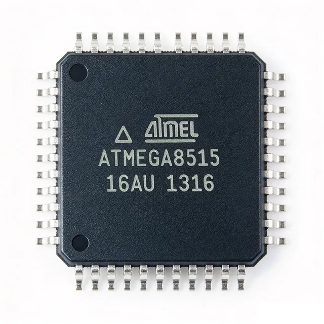
ATMEGA8515-16AU - 8-bit AVR MCU 16MHz 8KB Flash 44-TQFP
MPN: ATMEGA8515-16AU ✓ Aktif| Kwantitas | Harga Satuan | Lengkap |
|---|---|---|
| 1 | $4.37 | $4,37 |
| 10 | $4.05 | $40,50 |
| 100 | $3.62 | $362,00 |
| 500 | $3.2 | $1.600,00 |
| 1.000 | $2.85 | $2.850,00 |
ATMEGA8515-16AU Ringkasan
Background Knowledge: An 8-bit microcontroller (MCU) is a single-chip computer integrating a CPU core, program memory, data memory, and peripherals around an 8-bit data bus. The ATmega8515 belongs to the AVR enhanced RISC family — a Harvard-architecture core that executes most instructions in a single clock cycle, achieving roughly 1 MIPS per MHz. Within the broader taxonomy, it sits as: 8-bit microcontroller -> microcontroller -> embedded processor -> semiconductor. The RISC (Reduced Instruction Set Computer) approach trades a larger, fixed-length instruction set for simpler, faster pipeline execution, making AVR MCUs popular in hobbyist, industrial, and educational designs.
Key differentiating features of this part include: 130 powerful RISC instructions (most single-cycle), 35 programmable I/O lines, two 8-bit timer/counters plus one 16-bit timer/counter, a full-duplex hardware USART, an SPI serial interface, an analog comparator, programmable watchdog timer with on-chip oscillator, and six sleep modes for power optimization. The device operates from 4.5 V to 5.5 V (the “16” speed grade at 16 MHz).
Technical depth: The AVR core uses on-chip Flash for program storage, allowing in-system programming via SPI or parallel modes. The 64 KB external SRAM interface is multiplexed and supports both SRAM and memory-mapped peripherals, enabling designs that require more RAM than the on-chip 512 B can provide. The internal bandgap reference and on-chip calibrated RC oscillator reduce external component count, while the JTAG (IEEE 1149.1-compliant) interface supports on-chip debug via tools such as the AVR JTAGICE or Atmel-ICE.
Typical applications include industrial control systems, sensor interface nodes, human-machine interface (HMI) front panels, building automation controllers, and Arduino-compatible firmware development through community packages such as MCUdude MajorCore. The wide operating voltage and robust I/O drive capability also suit automotive body electronics and white-goods appliance controllers.
When designing with this part, ensure the external SRAM interface traces are kept short and the AVCC pin is properly decoupled (100 nF + 10 µF) to avoid ADC noise coupling — even if the ADC is unused. The reset pin should be pulled up with a 10 kΩ resistor to VCC and fitted with a 100 nF capacitor to ground for noise immunity.
This page synthesizes distributor pricing, drop-in alternatives, design notes, and pin-level information not consolidated on a single manufacturer datasheet — supporting engineers evaluating the ATmega8515 for new designs or as a long-term supply alternative to newer ATmega variants.
Alternatif penggantian untuk ATMEGA8515-16AU — paket yang sama, pin-pada-pin kompatibel. Bagian paket yang berbeda memerlukan kerja ulang PCB diabaikan.
Variasi di dalam seri ini
Model-series yang sama yang kompatibel dengan penggantian ATMEGA8515-16AU (sama faktor bentuk dan footprint) — berbeda di dalam Core Architecture, Package, Operating Temperature, Instruction Set, Communication Interfaces.
Alat Perbandingan Cepat — Pilih bagian alternatif untuk perbandingan paralel:
ATMEGA8515-16JU
Kontak untuk harga
Lihat Datasheet →ATMEGA8515-16MU
Kontak untuk harga
Lihat Datasheet →ATMEGA162-16AU
Kontak untuk harga
Lihat Datasheet →ATMEGA164A-AU
Kontak untuk harga
Lihat Datasheet →ATMEGA324PV-10AU
Kontak untuk harga
Lihat Datasheet →ATMEGA162V-8AU
Kontak untuk harga
Lihat Datasheet →AT90S8515-16AU
📋 Alternatif referensi (tidak dalam katalog)
ATMEGA8515-16AU Rating Maksimal & Karakteristik Listrik
| Core Architecture | AVR enhanced RISC (8-bit) |
| Instruction Set | 130 instructions, mostly single-cycle |
| Maximum CPU Frequency | 16 MHz |
| Throughput | 16 MIPS at 16 MHz |
| Program Memory (Flash) | 8 KB (4K x 16) |
| SRAM | 512 B internal |
| External SRAM Support | Up to 64 KB |
| EEPROM | 512 B |
| Operating Voltage (VCC) | 4.5 V to 5.5 V |
| I/O Pins | 35 programmable |
| Timers/Counters | 2x 8-bit + 1x 16-bit |
| Communication Interfaces | USART, SPI, JTAG |
| Analog Comparator | Yes |
| Watchdog Timer | Yes, with on-chip oscillator |
| Paket | 44-TQFP (10x10 mm) |
| Tipe Mounting | Surface Mount |
| Suhu Kerja | -40 C to +85 C |
| Speed Grade | -16 (16 MHz @ 5V) |
| Status RoHS | Compliant |
| Lead-Free | Yes |
Konfigurasi Pin ATMEGA8515-16AU
| Pin produk 1 | PA0 — Port A bit 0 / external memory address bit 8 (AD8) |
| Pin produk 2 | PA1 — Port A bit 1 / AD9 |
| Pin produk 3 | PA2 — Port A bit 2 / AD10 |
| Pin produk 4 | PA3 — Port A bit 3 / AD11 |
| Pin produk 5 | PA4 — Port A bit 4 / AD12 |
| Pin produk 6 | PA5 — Port A bit 5 / AD13 |
| Pin produk 7 | PA6 — Port A bit 6 / AD14 |
| Pin produk 8 | PA7 — Port A bit 7 / AD15 |
| Pin produk 9 | RESET — Reset input (active low) |
| Pin produk 10 | PB0 — Port B bit 0 (T0, timer/counter 0 external input) |
| Pin produk 11 | PB1 — Port B bit 1 (T1, timer/counter 1 external input) |
| Pin produk 12 | PB2 — Port B bit 2 (AIN0, analog comparator positive input) |
| Pin produk 13 | PB3 — Port B bit 3 (AIN1, analog comparator negative input) |
| Pin produk 14 | PB4 — Port B bit 4 (SS, SPI slave select) |
| Pin produk 15 | PB5 — Port B bit 5 (MOSI, SPI master out) |
| Pin produk 16 | PB6 — Port B bit 6 (MISO, SPI master in) |
| Pin produk 17 | PB7 — Port B bit 7 (SCK, SPI clock) |
| Pin produk 18 | PE0 — Port E bit 0 (INT0, external interrupt 0) |
| Pin produk 19 | PE1 — Port E bit 1 (INT1, external interrupt 1) |
| Pin produk 20 | GND — Ground |
| Pin produk 21 | PC0 — Port C bit 0 / external memory data bit 0 (A8) |
| Pin produk 22 | PC1 — Port C bit 1 / A9 |
| Pin produk 23 | PC2 — Port C bit 2 / A10 |
| Pin produk 24 | PC3 — Port C bit 3 / A11 |
| Pin produk 25 | PC4 — Port C bit 4 / A12 |
| Pin produk 26 | PC5 — Port C bit 5 / A13 |
| Pin produk 27 | PC6 — Port C bit 6 / A14 |
| Pin produk 28 | PC7 — Port C bit 7 / A15 |
| Pin produk 29 | ALE — Address Latch Enable for external memory |
| Pin produk 30 | AVCC — Analog supply voltage (for ADC reference) |
| Pin produk 31 | GND — Ground |
| Pin produk 32 | PD0 — Port D bit 0 (RXD, USART receive) |
| Pin produk 33 | PD1 — Port D bit 1 (TXD, USART transmit) |
| Pin produk 34 | PD2 — Port D bit 2 (INT2, external interrupt 2) |
| Pin produk 35 | PD3 — Port D bit 3 (OC1B, timer1 compare B) |
| Pin produk 36 | PD4 — Port D bit 4 (OC1A, timer1 compare A) |
| Pin produk 37 | PD5 — Port D bit 5 (WR, external memory write strobe) |
| Pin produk 38 | PD6 — Port D bit 6 (RD, external memory read strobe) |
| Pin produk 39 | PD7 — Port D bit 7 (ICP, timer1 input capture) |
| Pin produk 40 | VCC — Digital supply voltage |
| Pin produk 41 | XTAL2 — Crystal oscillator output |
| Pin produk 42 | XTAL1 — Crystal oscillator input |
| Pin produk 43 | TOSC1 — Timer oscillator pin 1 (32 kHz crystal) |
| Pin produk 44 | TOSC2 — Timer oscillator pin 2 (32 kHz crystal) |
Aplikasi Umum
ATMEGA8515-16AU cocok untuk 7 aplikasis: Industrial Control Systems, Human-Machine Interface (HMI) Front Panels, Building Automation Controllers, Arduino-Compatible Firmware Development, Sensor Interface Nodes, White-Goods Appliance Controllers, Legacy Parallel-Memory Embedded Designs.
Industrial Control Systems
The ATMEGA8515-16AU fits industrial control because of its 16 MHz throughput (16 MIPS), 35 programmable I/O lines, and external SRAM interface supporting up to 64 KB — sufficient for PLC-style logic, sensor polling, and actuator control loops. Its 4.5–5.5 V VCC matches 5 V industrial backplanes, while six sleep modes support low-duty-cycle remote nodes. Pairing it with an RS-485 transceiver (e.g., ADM1485) on USART enables reliable MODBUS communication across factory floors, and the 16-bit timer/counter delivers precise PWM for motor or valve actuation.
Direkomendasikan
Human-Machine Interface (HMI) Front Panels
With 35 I/O pins and an SPI port, the ATMEGA8515-16AU can directly drive character LCDs, keypads, LED matrices, and rotary encoders in HMI front-panel designs. Its 8 KB Flash accommodates menu-state firmware while 512 B SRAM handles input debouncing and display buffers. The hardware USART bridges to a main controller or PLC, and the analog comparator enables backlight dimming via a light sensor. Compared with bit-banged I/O expansion chips, the ATmega8515's hardware peripherals reduce firmware complexity and CPU overhead.
Direkomendasikan
Building Automation Controllers
Building automation requires reliable 24/7 operation at low cost — a sweet spot for the ATMEGA8515-16AU. Its industrial temperature range (-40 to +85 °C), low power consumption in sleep modes (<1 µA typical), and 8 KB Flash support HVAC scheduling, lighting control, and security sensor nodes. The USART connects to BACnet or MODBUS networks via RS-485, while the 16-bit timer/counter handles triac zero-crossing dimming. With 35 I/O pins, a single MCU can read multiple thermistors, drive relays, and scan keypads without external I/O expanders.
Direkomendasikan
Arduino-Compatible Firmware Development
Through community packages like MCUdude MajorCore, the ATMEGA8515-16AU can be programmed with the Arduino IDE, making it a strong choice for hobbyist projects, rapid prototyping, and educational kits. Its 8 KB Flash is sufficient for typical Arduino sketches, while the 16 MHz clock delivers responsive loop times. The 44-TQFP package exposes more I/O than the typical Arduino UNO ATmega328P, allowing expansion boards to leverage additional pins. JTAG debug via Atmel-ICE is supported for production-grade debugging beyond Arduino's serial monitor.
Direkomendasikan
Sensor Interface Nodes
The ATMEGA8515-16AU serves as a sensor aggregation node where 35 I/O pins accept multiple analog and digital sensor inputs. Although it lacks a built-in ADC, the analog comparator paired with an external RC network can implement sigma-delta conversion for thermistor or photodiode readings. USART and SPI interfaces transmit aggregated sensor data to a host controller or gateway. The external SRAM interface (up to 64 KB) supports data buffering during network outages, and the watchdog timer ensures the node recovers from firmware hangs in remote deployments.
Direkomendasikan
White-Goods Appliance Controllers
Washing machines, dishwashers, ovens, and refrigerators benefit from the ATMEGA8515-16AU's blend of cost-effectiveness, robust I/O count, and industrial temperature range. Its timers drive triac-controlled heating elements, motor relays, and solenoid valves while the USART connects to display modules or inverter boards. Six sleep modes reduce standby power below 1 mW — important for ENERGY STAR compliance. The 8 KB Flash holds state-machine firmware for wash cycles, while 512 B EEPROM retains user settings and fault logs across power cycles.
Direkomendasikan
Legacy Parallel-Memory Embedded Designs
The ATMEGA8515-16AU's distinctive external memory interface (supporting up to 64 KB SRAM) makes it a fit for designs requiring more RAM than the on-chip 512 B can provide — for example, data-logging buffers, character-LCD frame buffers, or protocol stacks with large state tables. The address and data buses on ports A and C support both SRAM and memory-mapped peripherals. Engineers migrating from older AT90S8515 designs benefit from code compatibility while gaining modern AVR enhancements such as the analog comparator and improved interrupt controller.
Direkomendasikan
Ringkasan Produk Direkomendasikan
Data referensi engineering untuk ATMEGA8515-16AU — pembandingan, panduan desain, dan informasi konformitas.
Panduan Pemilihan
Pembandingan dengan Alternatif
| Parameter Umum | Produk Ini | ATMEGA8515-16JU | ATMEGA8515-16MU | AT90S8515-16AU | ATmega162-16AU |
|---|---|---|---|---|---|
| Brand | Microchip Technology | Microchip Technology | Microchip Technology | Microchip Technology (legacy) | Microchip Technology |
| Package | 44-TQFP (10x10 mm) | 44-TQFP (10x10 mm) - same | 44-VQFN (7x7 mm) - same pin function | 44-TQFP (10x10 mm) - same | 44-TQFP (10x10 mm) - same |
| Flash Memory | 8 KB | 8 KB | 8 KB | 8 KB | 16 KB (+100%) |
| SRAM | 512 B | 512 B | 512 B | 512 B | 1 KB (+100%) |
| EEPROM | 512 B | 512 B | 512 B | 512 B | 512 B |
| Max CPU Frequency | 16 MHz | 16 MHz | 16 MHz | 16 MHz | 16 MHz |
| Operating Voltage | 4.5 V to 5.5 V | 4.5 V to 5.5 V | 4.5 V to 5.5 V | 4.5 V to 5.5 V | 2.7 V to 5.5 V (wider range) |
| I/O Pins | 35 | 35 | 35 | 35 | 35 |
| USART Channels | 1 | 1 | 1 | 1 | 2 (dual USART) |
| External Memory Interface | Up to 64 KB SRAM | Up to 64 KB SRAM | Up to 64 KB SRAM | Up to 64 KB SRAM | Up to 64 KB SRAM |
Diferensiator Kunci
- External SRAM interface supporting up to 64 KB (vsATMEGA328P-AUR)
- Dual 8-bit + one 16-bit timer/counter architecture (vsATmega162-16AU)
- Mature, long-term supported AVR core (vsATMEGA324PV-10AU)
- Lower unit cost than higher-memory AVR variants (vsATmega162-16AU)
Catatan Desain
Decouple the ATMEGA8515-16AU with a 100 nF ceramic capacitor placed within 5 mm of each VCC pin (pin 40) and AVCC pin (pin 30). Add a bulk 10 µF tantalum or aluminum-polymer capacitor on each supply rail. The AVCC pin should be tied to VCC through a ferrite bead or small inductor to isolate analog supply noise from the digital domain. Always tie the AGND pin (pin 31) directly to the ground plane for low-impedance return paths.
For the external memory interface, keep address and data bus traces as short as possible and matched in length (within ±5 mm) to minimize skew. Route the ALE, RD, and WR strobes with controlled impedance and avoid right-angle bends. Place external SRAM chips adjacent to the MCU with the shortest possible bus. Use a 4-layer PCB with dedicated ground and power planes to reduce EMI and crosstalk on the parallel bus.
Do not leave the RESET pin (pin 9) floating — always pull it up to VCC with a 10 kΩ resistor and add a 100 nF capacitor to ground for noise immunity. Brown-out detector (BOD) levels must be configured for 4.5 V operation at 16 MHz; running below 4.5 V without BOD can cause Flash corruption. When using the analog comparator, ensure AIN0/AIN1 traces are short and guarded from digital switching signals to prevent false triggering.
The 44-TQFP package has a thermal resistance of approximately 50 °C/W (theta_JA) on a standard 2-layer PCB. The ATMEGA8515 typically dissipates <100 mW even at full 16 MIPS, so no heatsink is required. However, in enclosed industrial enclosures with elevated ambient temperatures (>60 °C), ensure adequate airflow or thermal vias under the exposed pad to keep junction temperature below 125 °C for reliable long-term operation.
Informasi Konformitas
RoHS compliant per Microchip product page. Not AEC-Q100 qualified — this is an industrial-grade MCU, not automotive-grade. Lead-free TQFP package standard.
