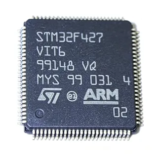
LPC2368FBD100 - ARM7 72MHz 512KB Flash MCU | NXP
MPN: LPC2368FBD100 ✓ AktifLPC2368FBD100 Ringkasan
An ARM7 microcontroller is a 32-bit RISC processor core that executes both the 32-bit ARM and the 16-bit Thumb instruction set, allowing code-density and performance trade-offs. The ARM7TDMI-S variant adds a hardware multiplier and embedded ICE debug logic. Within NXP's portfolio, the LPC2300 family sits at the top of the legacy LPC2000 ARM7 line, ahead of the smaller LPC2100 and LPC2200 series, and is itself succeeded by the Cortex-M3 based LPC1700 family. Peripherals are tightly integrated to minimize external components in industrial Ethernet, USB, and CAN nodes. The device operates from a single 3.0 V to 3.6 V supply, with I/O tolerant to 5 V, and is housed in a 100-pin LQFP (14 x 14 mm) package suitable for cost-sensitive 4-layer PCB layouts.
Key features include 72 MHz maximum CPU clock with on-chip PLL, 32 kB SRAM usable as battery-backed retention, vectored interrupt controller for deterministic real-time response, and ISP/IAP in-application programming via UART or CAN. The Ethernet MAC supports 10/100 Mbps MII/RMII with full-duplex operation, while the USB 2.0 controller supports device, host, and OTG roles. The ADC delivers 400 ksps across 8 channels at 10-bit resolution, and the DAC is a 10-bit rail-to-rail converter suitable for waveform generation.
Typical applications include industrial Ethernet gateways, building automation controllers, USB peripherals and embedded hosts, CAN-based automotive body modules, point-of-sale terminals, and small-scale motor-control boards. Designers choose the LPC2368FBD100 when ARM7 firmware, a wide peripheral mix, and 512 kB of on-chip flash are required without an external memory bus.
When designing with this device, ensure the 3.3 V analog supply (V3A) is decoupled with at least 100 nF plus a 10 uF bulk, and isolate it from the digital 3.3 V plane to avoid ADC/DAC noise coupling. The VBAT domain supports RTC backup and 32 kB of retained SRAM; route a small lithium cell or supercap there to preserve RTC time across power cycles.
Alternatif penggantian untuk LPC2368FBD100 — paket yang sama, pin-pada-pin kompatibel. Bagian paket yang berbeda memerlukan kerja ulang PCB diabaikan.
Variasi di dalam seri ini
Model-series yang sama yang kompatibel dengan penggantian LPC2368FBD100 (sama faktor bentuk dan footprint) — berbeda di dalam ADC, DAC, Ethernet MAC, Operating Temperature, Package.
LPC2364FET100
✅ Drop-InKontak untuk harga
Lihat Datasheet →LPC2366FBD100
✅ Drop-In📋 Alternatif referensi (tidak dalam katalog)
LPC2367FBD100
✅ Drop-In📋 Alternatif referensi (tidak dalam katalog)
LPC2368FBD100K
✅ Drop-In📋 Alternatif referensi (tidak dalam katalog)
LPC2368FBD100-S
✅ Drop-In📋 Alternatif referensi (tidak dalam katalog)
LPC2368FBD100 Rating Maksimal & Karakteristik Listrik
| Core Architecture | ARM7TDMI-S (16/32-bit) |
| Maximum CPU Clock | 72 MHz |
| Flash Memory | up to 512 kB |
| SRAM | up to 58 kB (32 kB battery-backed) |
| Supply Voltage (Vdd) | 3.0 V to 3.6 V |
| I/O Voltage Tolerance | 5 V tolerant |
| Ethernet MAC | 10/100 Mbps MII/RMII |
| USB Controller | USB 2.0 Device/Host/OTG |
| ADC | 10-bit, 8-channel, 400 ksps |
| DAC | 10-bit |
| CAN Channels | 2 (CAN 2.0B) |
| UART | 4 |
| SSP/SPI | 3 |
| I2C | 3 |
| I2S | 1 |
| PWM | 2 (Motor Control PWM) |
| General-Purpose Timers | 4 |
| DMA Controller | Yes (GPDMA) |
| External Memory Bus | Yes (8/16/32-bit) |
| Paket | LQFP-100 (14 x 14 mm, 0.5 mm pitch) |
| Suhu Kerja | -40 C to +85 C |
| Status RoHS | Compliant |
Konfigurasi Pin LPC2368FBD100
| Pin produk 1 | P0[0]/TXD3 — GPIO / UART3 TXD |
| Pin produk 2 | P0[1]/RXD3 — GPIO / UART3 RXD |
| Pin produk 3 | P0[2]/SCL1 — GPIO / I2C1 SCL |
| Pin produk 4 | P0[3]/SDA1 — GPIO / I2C1 SDA |
| Pin produk 5 | P0[4]/SCK0/CAP2[0] — GPIO / SSP0 SCK / Timer2 capture |
| Pin produk 6 | P0[5]/MISO0/MAT2[0] — GPIO / SSP0 MISO / Timer2 match |
| Pin produk 7 | P0[6]/MOSI0/MAT2[1] — GPIO / SSP0 MOSI / Timer2 match |
| Pin produk 8 | P0[7]/SSEL0/MAT2[2] — GPIO / SSP0 SSEL / Timer2 match |
| Pin produk 9 | P0[8]/TXD2/MAT2[3] — GPIO / UART2 TXD / Timer2 match |
| Pin produk 10 | P0[9]/RXD2/MAT3[0] — GPIO / UART2 RXD / Timer3 match |
| Pin produk 11 | P0[10]/SDA2/MAT3[1] — GPIO / I2C2 SDA / Timer3 match |
| Pin produk 12 | P0[11]/SCL2/MAT3[2] — GPIO / I2C2 SCL / Timer3 match |
| Pin produk 13 | P0[12]/MISO1/AD0[6] — GPIO / SSP1 MISO / ADC0 ch6 |
| Pin produk 14 | P0[13]/MOSI1/AD0[7] — GPIO / SSP1 MOSI / ADC0 ch7 |
| Pin produk 15 | P0[14]/SSEL1/USB_SCL — GPIO / SSP1 SSEL / USB SCL |
| Pin produk 16 | P0[15]/USB_SDA — GPIO / USB SDA |
| Pin produk 17 | P0[16]/RXD1/SSEL0/CAP1[0] — GPIO / UART1 RXD / SSP0 SSEL / Timer1 capture |
| Pin produk 18 | P0[17]/TXD1/CAP1[1] — GPIO / UART1 TXD / Timer1 capture |
| Pin produk 19 | P0[18]/DCD1/CAP1[2] — GPIO / UART1 DCD / Timer1 capture |
| Pin produk 20 | P0[19]/DSR1/CAP1[3] — GPIO / UART1 DSR / Timer1 capture |
| Pin produk 21 | P0[20]/DTR1/MAT1[0] — GPIO / UART1 DTR / Timer1 match |
| Pin produk 22 | P0[21]/RI1/MAT1[1] — GPIO / UART1 RI / Timer1 match |
| Pin produk 23 | P0[22]/RTS1/MAT1[2] — GPIO / UART1 RTS / Timer1 match |
| Pin produk 24 | P0[23]/CTS1/MAT1[3] — GPIO / UART1 CTS / Timer1 match |
| Pin produk 25 | P0[24]/PWM1[1]/AD0[1] — GPIO / PWM1 channel 1 / ADC0 ch1 |
| Pin produk 26 | P0[25]/AOUT — GPIO / DAC output |
| Pin produk 27 | P0[26]/AD0[3]/RXD3 — GPIO / ADC0 ch3 / UART3 RXD |
| Pin produk 28 | P0[27]/SCL0 — GPIO / I2C0 SCL |
| Pin produk 29 | P0[28]/SDA0/MAT0[0] — GPIO / I2C0 SDA / Timer0 match |
| Pin produk 30 | P0[29]/USB_D+ — GPIO / USB D+ |
| Pin produk 31 | P0[30]/USB_D- — GPIO / USB D- |
| Pin produk 32 | P0[31]/USB_VBUS — GPIO / USB VBUS sense |
| Pin produk 33 | Vss — Ground |
| Pin produk 34 | Vdd — Digital 3.3 V supply |
| Pin produk 35 | Vdd — Digital 3.3 V supply |
| Pin produk 36 | P1[0]/ENET_TXD0 — GPIO / Ethernet MAC TXD0 |
| Pin produk 37 | P1[1]/ENET_TXD1 — GPIO / Ethernet MAC TXD1 |
| Pin produk 38 | P1[4]/ENET_TX_EN — GPIO / Ethernet MAC TX_EN |
| Pin produk 39 | P1[8]/ENET_CRS — GPIO / Ethernet MAC CRS |
| Pin produk 40 | P1[9]/ENET_RXD0 — GPIO / Ethernet MAC RXD0 |
| Pin produk 41 | P1[10]/ENET_RXD1 — GPIO / Ethernet MAC RXD1 |
| Pin produk 42 | P1[14]/ENET_RX_ER — GPIO / Ethernet MAC RX_ER |
| Pin produk 43 | P1[15]/ENET_REF_CLK — GPIO / Ethernet MAC reference clock |
| Pin produk 44 | P1[16]/ENET_MDC — GPIO / Ethernet MAC MDC |
| Pin produk 45 | P1[17]/ENET_MDIO — GPIO / Ethernet MAC MDIO |
| Pin produk 46 | P1[18]/PWM1[1]/CAP1[0] — GPIO / PWM1 ch1 / Timer1 capture |
| Pin produk 47 | P1[19]/MCPWM0_ABORT — GPIO / Motor PWM abort |
| Pin produk 48 | P1[20]/MCI0_FB — GPIO / Motor PWM feedback |
| Pin produk 49 | P1[21]/PWM0[5]/MCFB0 — GPIO / PWM0 ch5 / Motor control FB0 |
| Pin produk 50 | P1[22]/PWM0[4]/MCFB1 — GPIO / PWM0 ch4 / Motor control FB1 |
| Pin produk 51 | P1[23]/PWM0[2]/MCFB2 — GPIO / PWM0 ch2 / Motor control FB2 |
| Pin produk 52 | P1[24]/PWM0[3] — GPIO / PWM0 ch3 |
| Pin produk 53 | P1[25]/PWM0[1] — GPIO / PWM0 ch1 |
| Pin produk 54 | P1[26]/PWM0[0] — GPIO / PWM0 ch0 |
| Pin produk 55 | P1[27]/CLKOUT — GPIO / CLKOUT |
| Pin produk 56 | P1[28]/MAT0[0]/PWM1[2] — GPIO / Timer0 match / PWM1 ch2 |
| Pin produk 57 | P1[29]/MAT0[1]/PWM1[3] — GPIO / Timer0 match / PWM1 ch3 |
| Pin produk 58 | P1[30]/AD0[4] — GPIO / ADC0 ch4 |
| Pin produk 59 | P1[31]/AD0[5] — GPIO / ADC0 ch5 |
| Pin produk 60 | Vss — Ground |
| Pin produk 61 | Vdd — Digital 3.3 V supply |
| Pin produk 62 | P2[0]/PWM1[1]/DQFLAGIN — GPIO / PWM1 ch1 / SDRAM DQ flag in |
| Pin produk 63 | P2[1]/PWM1[2]/DQFLAGOUT — GPIO / PWM1 ch2 / SDRAM DQ flag out |
| Pin produk 64 | P2[2]/PWM1[3]/D13 — GPIO / PWM1 ch3 / EMD data 13 |
| Pin produk 65 | P2[3]/PWM1[4]/D14 — GPIO / PWM1 ch4 / EMD data 14 |
| Pin produk 66 | P2[4]/PWM1[5]/D15 — GPIO / PWM1 ch5 / EMD data 15 |
| Pin produk 67 | P2[5]/PWM1[6]/D16 — GPIO / PWM1 ch6 / EMD data 16 |
| Pin produk 68 | P2[6]/PWM1[7]/D17 — GPIO / PWM1 ch7 / EMD data 17 |
| Pin produk 69 | P2[7]/D18 — GPIO / EMD data 18 |
| Pin produk 70 | P2[8]/D19 — GPIO / EMD data 19 |
| Pin produk 71 | P2[9]/D20 — GPIO / EMD data 20 |
| Pin produk 72 | P2[10]/D21 — GPIO / EMD data 21 |
| Pin produk 73 | P2[11]/D22 — GPIO / EMD data 22 |
| Pin produk 74 | P2[12]/D23 — GPIO / EMD data 23 |
| Pin produk 75 | P2[13]/D24 — GPIO / EMD data 24 |
| Pin produk 76 | P2[14]/D25 — GPIO / EMD data 25 |
| Pin produk 77 | P2[15]/D26 — GPIO / EMD data 26 |
| Pin produk 78 | P2[16]/D27 — GPIO / EMD data 27 |
| Pin produk 79 | P2[17]/D28 — GPIO / EMD data 28 |
| Pin produk 80 | P2[18]/D29 — GPIO / EMD data 29 |
| Pin produk 81 | P2[19]/D30 — GPIO / EMD data 30 |
| Pin produk 82 | P2[20]/D31 — GPIO / EMD data 31 |
| Pin produk 83 | P2[21]/A22 — GPIO / External memory address 22 |
| Pin produk 84 | P2[22]/A23 — GPIO / External memory address 23 |
| Pin produk 85 | P2[23]/A20/OE — GPIO / Address 20 / Output enable |
| Pin produk 86 | P2[24]/A21/BLS3 — GPIO / Address 21 / Byte lane strobe 3 |
| Pin produk 87 | P2[25]/CS1 — GPIO / Chip select 1 |
| Pin produk 88 | P2[26]/CS2 — GPIO / Chip select 2 |
| Pin produk 89 | P2[27]/CS3 — GPIO / Chip select 3 |
| Pin produk 90 | P2[28]/A19/CLKOUT2 — GPIO / Address 19 / CLKOUT2 |
| Pin produk 91 | P2[29]/A18/CLKOUT3 — GPIO / Address 18 / CLKOUT3 |
| Pin produk 92 | P2[30]/A17 — GPIO / Address 17 |
| Pin produk 93 | P2[31]/A16 — GPIO / Address 16 |
| Pin produk 94 | RTCK — JTAG RTCK (return clock) |
| Pin produk 95 | TMS — JTAG TMS |
| Pin produk 96 | TDO — JTAG TDO |
| Pin produk 97 | TDI — JTAG TDI |
| Pin produk 98 | TCK — JTAG TCK |
| Pin produk 99 | RSTOUT — Reset output |
| Pin produk 100 | RESET — External reset input (active low) |
Aplikasi Umum
LPC2368FBD100 cocok untuk 7 aplikasis: Industrial Ethernet Gateway / PLC, USB Embedded Host / Device Controller, Building Automation / HVAC Controller, Automotive Body / CAN Gateway Module, Point-of-Sale (POS) Terminal, Small-Scale Motor Control / BLDC Driver, Data Acquisition / Industrial Sensor Hub.
Industrial Ethernet Gateway / PLC
The LPC2368FBD100's on-chip 10/100 Ethernet MAC and full-duplex MII/RMII make it an ideal main controller for Modbus TCP, EtherNet/IP, or PROFINET gateways, replacing external MAC chips. Its ARM7TDMI-S at 72 MHz delivers sufficient headroom for TCP/IP stacks while two CAN 2.0B channels allow bridging to legacy industrial buses. Placed on a 4-layer board with a 3.3 V analog island, it gives deterministic performance with 32 kB of battery-backed SRAM retaining configuration across power loss.
Direkomendasikan
USB Embedded Host / Device Controller
The LPC2368FBD100's integrated USB 2.0 controller supports Device, Host, and OTG roles, allowing firmware-driven USB stacks for mass-storage hosts, HID peripherals, or CDC devices without an external interface IC. The on-chip 512 kB flash accommodates USB class drivers and FAT32 file systems, while 58 kB SRAM buffers bulk transfers. Compared to discrete USB solutions it removes BOM cost and PCB area, especially when paired with the on-chip DMA controller to offload endpoint handling from the CPU.
Direkomendasikan
Building Automation / HVAC Controller
Building automation controllers need a wide peripheral mix on a single chip - the LPC2368FBD100 provides 4 UARTs for RS-485 trunks, 3 I2C buses for sensor and EEPROM access, an SD/MMC interface for local data logging, and an 8-channel 10-bit ADC for analog temperature and humidity inputs. The 32 kB battery-backed SRAM preserves scheduler state across power cycles, while the RTC with VBAT domain keeps accurate time-stamping. Its 3.0-3.6 V supply with 5 V tolerant I/O allows direct connection to industrial 24 V conditioned sensor lines.
Direkomendasikan
Automotive Body / CAN Gateway Module
Automotive body controllers and CAN gateways benefit from the LPC2368FBD100's dual CAN 2.0B channels and 72 MHz ARM7 core running OBD-II or CANopen stacks. Although the part is not AEC-Q100 qualified (it is industrial grade -40 to +85 C), it remains widely used in non-safety automotive nodes such as infotainment auxiliary MCUs and diagnostic bridges. The Ethernet MAC plus dual CAN combination is uniquely strong for telematics control units forwarding CAN traffic over automotive Ethernet.
Direkomendasikan
Point-of-Sale (POS) Terminal
POS terminals need USB, Ethernet, multiple serial peripherals, and secure firmware storage - the LPC2368FBD100's 512 kB flash supports encrypted boot loaders, its 58 kB SRAM handles transaction buffers, and its on-chip USB OTG allows direct connection to printers or PIN pads. Compared to Cortex-M0 alternatives, the 72 MHz ARM7 delivers faster DES/AES for legacy payment flows. The LQFP-100 package and 5 V-tolerant GPIO simplify mixed-voltage peripheral boards.
Direkomendasikan
Small-Scale Motor Control / BLDC Driver
The LPC2368FBD100 includes 2 dedicated motor-control PWM blocks with quadrature encoder input, suited to small BLDC or stepper control up to a few hundred watts. The 10-bit ADC samples back-EMF and current sense, while the 10-bit DAC provides a programmable reference. ARM7 latency at 72 MHz is fast enough for 20 kHz PWM loops with PI control, and the dual CAN channels expose drive status to a vehicle or machine network.
Direkomendasikan
Data Acquisition / Industrial Sensor Hub
Industrial sensor hubs route analog inputs to Ethernet or CAN backbones - the LPC2368FBD100's 8-channel 10-bit ADC at 400 ksps handles multi-sensor scanning, while its on-chip Ethernet MAC streams the data to a SCADA server. With 58 kB SRAM it can buffer 4 kSamples between transmissions. The 5 V tolerant GPIO accepts legacy 4-20 mA loop signals through external resistor networks without additional level shifters, simplifying the analog front end.
Direkomendasikan
Ringkasan Produk Direkomendasikan
Data referensi engineering untuk LPC2368FBD100 — pembandingan, panduan desain, dan informasi konformitas.
Panduan Pemilihan
Pembandingan dengan Alternatif
| Parameter Umum | Produk Ini | LPC2364FET100 | LPC2366FBD100 | LPC2367FBD100 | LPC2368FBD100K |
|---|---|---|---|---|---|
| Brand | NXP Semiconductors | NXP Semiconductors | NXP Semiconductors | NXP Semiconductors | NXP Semiconductors |
| Package | LQFP-100 (14x14 mm) | LQFP-100 (14x14 mm) - same | LQFP-100 (14x14 mm) - same | LQFP-100 (14x14 mm) - same | LQFP-100 (14x14 mm) - same |
| Core Architecture | ARM7TDMI-S 72 MHz | ARM7TDMI-S 72 MHz | ARM7TDMI-S 72 MHz | ARM7TDMI-S 72 MHz | ARM7TDMI-S 72 MHz |
| Flash Memory | 512 kB | 128 kB (-75%) | 256 kB (-50%) | 512 kB (same) | 512 kB (same) |
| Ethernet MAC | 10/100 MII/RMII | 10/100 MII/RMII | 10/100 MII/RMII | 10/100 MII/RMII | 10/100 MII/RMII |
| USB Controller | USB 2.0 Device/Host/OTG | USB 2.0 Device/Host/OTG | USB 2.0 Device/Host/OTG | USB 2.0 Device/Host/OTG | USB 2.0 Device/Host/OTG |
| CAN Channels | 2 | 2 | 2 | 2 | 2 |
| Operating Temperature | -40 C to +85 C | -40 C to +85 C | -40 C to +85 C | -40 C to +85 C | -40 C to +85 C |
Diferensiator Kunci
- Highest flash density in the LPC236x LQFP-100 family (vsLPC2366FBD100)
- Largest SRAM with battery backup (vsLPC2367FBD100)
- Integrated Ethernet MAC plus USB OTG plus dual CAN in one chip (vsSTM32F107VBT6 (closest cross-brand competitor))
Catatan Desain
The LPC2368FBD100 has separate digital (Vdd) and analog (V3A/Vdda) supply domains. Per the NXP datasheet, decouple each Vdd pin with 100 nF X7R plus a shared 10 uF bulk, and isolate V3A with a ferrite from Vdd to minimize ADC and DAC noise. VBAT should be tied to a small lithium cell or supercap through a 1 kohm isolation resistor to retain the RTC and 32 kB backup SRAM across power loss.
The LQFP-100 (14 x 14 mm, 0.5 mm pitch) package benefits from a 4-layer PCB with a continuous ground plane on layer 2. Keep Ethernet MAC traces (P1[0..17]) short and length-matched within 25 mm to the PHY (KSZ8041 etc.) to avoid MII timing violations. Place the 12 MHz crystal within 5 mm of XTAL1/XTAL2 with a guarded ground ring to suppress EMI from the 72 MHz PLL output.
Do NOT assume the LPC1768FBD100 is a drop-in replacement - it is a Cortex-M3 part with different pin mapping (notably pin 13). ISP/IAP via UART0 requires the external pins P0[14] and P0[15] to be configured correctly during reset; if the BOOT pins are mis-pulled, firmware can lock itself out and require JTAG recovery. The USB_VBUS pin (P0[31]) must be connected even if USB is unused, otherwise VBUS sensing fails and the USB block cannot enter suspend correctly.
Estimated: at 72 MHz CPU clock with all peripherals active, the LPC2368FBD100 typically draws 40-55 mA from Vdd (3.3 V). Power dissipation is therefore ~150 mW, well within the LQFP-100 thermal resistance of approximately 50 C/W (per NXP package data). No heatsink is required, but designers should still provide continuous copper under the exposed die-pad-adjacent ground leads for best thermal relief in enclosed industrial housings.
The on-chip Ethernet MAC drives MII/RMII signals at 25 MHz / 50 MHz respectively - keep these traces over a continuous ground plane and series-terminate (33 ohm) near the MAC if the PHY is more than 50 mm away. USB D+/D- traces require 90-ohm differential impedance and should not have stubs; route them on the top layer only and keep total length below 50 mm.
Informasi Konformitas
RoHS and REACH compliant per NXP product page. Not AEC-Q100 qualified - this is an industrial-grade part (-40 C to +85 C). For automotive body modules the LPC2368 is generally acceptable in non-safety nodes but safety-critical ECUs should use an AEC-Q100 qualified MCU such as the NXP S32K series. Conflict-minerals statement available from NXP.