FPGA & CPLD
製品 (6666)

EPF8820ATC144-8 - FLEX 8000 8K Gate FPGA, 144-LQFP | Altera
The Altera EPF8820ATC144-8 is a member of the FLEX 8000 family of CMOS SRAM-based Field Programmable Gate Arrays, offering approximately 8,000 usable gates with 672 logic elements in a 144-pin LQFP (TQFP) surface-mount package. It is part of the legacy Altera programmable logic portfolio, originally released in the mid-1990s and now supported through Intel FPGA's mature-device lifecycle. The "-8" suffix designates a specific speed grade within the FLEX 8000 family, where lower numeric suffixes correspond to faster internal performance. A Field Programmable Gate Array (FPGA) is a semiconductor device built around an array of configurable logic blocks (CLBs) interconnected by a programmable routing matrix. FPGAs sit at the top of the programmable logic hierarchy: PAL/GAL (simple) -> CPLD (complex programmable logic device) -> FPGA (highest density, SRAM-based). The FLEX 8000 family pioneered Altera's look-up-table-based architecture combined with continuous interconnect, a design that influenced later device families such as ACEX, APEX, and Cyclone. Key features include 84 Logic Array Blocks (LABs), 112 user I/O pins, on-chip SRAM configuration memory, and support for MultiVolt I/O interfacing with 3.3V or 5.0V systems (excluding EPF8636A 84-pin variants). The device is configured at system power-up via an industry-standard parallel EPROM, an Altera serial configuration device (EPC1, EPC1213, EPC1064, EPC1441), or a system controller. The CMOS SRAM configuration approach allows in-system reconfiguration and unlimited reprogramming cycles. The FLEX 8000 architecture is fabricated on a 0.42 micrometer CMOS process with four-layer metal interconnect. Each Logic Element contains a 4-input look-up table, a programmable flip-flop, and dedicated carry and cascade chains that accelerate arithmetic and wide fan-in functions. Continuous FastTrack interconnect provides predictable routing delays across the device. The 144-pin LQFP package uses a 0.5 mm terminal pitch and offers a 31 mm x 31 mm body suitable for production through-hole-free assembly. Typical applications include industrial control glue logic, telecommunications interface adapters, legacy ASIC replacements, prototyping platforms, and military/aerospace systems requiring long-life programmable logic. Engineers continue to deploy EPF8820ATC144-8 designs where proven design IP, long-term availability through Altera/Intel's mature-device program, and a stable Quartus design flow outweigh the benefits of migrating to newer families. When designing with this device, ensure proper configuration is supplied at every power-up because SRAM-based FPGAs lose configuration on power-down. The JTAG boundary-scan and dedicated configuration pins must be correctly terminated, and the MAX+plus II or Quartus design software should be used for synthesis, place-and-route, and timing closure. Users targeting modern I/O standards should migrate to newer families like Cyclone or MAX 10. This page synthesizes distributor pricing, FLEX 8000 family drop-in alternatives, and practical design considerations not consolidated in the manufacturer datasheet alone, enabling engineers to evaluate the EPF8820ATC144-8 for both new and legacy design-in scenarios.

EPF8820ATI144-1 - FLEX 8000 FPGA 8K Gates, 1.8ns, TQFP-144 | Altera
The Altera EPF8820ATI144-1 is a member of the FLEX 8000 family of CMOS programmable logic devices, delivering up to 8,200 usable gates, 672 logic elements, and 112 I/O pins in a 144-pin TQFP (TQ144 / 0.500 mm pitch) industrial-grade package. Built on a 0.42 µm CMOS EPROM process, this device provides a propagation delay of approximately 1.8 ns and supports system clock frequencies up to 80 MHz. The FLEX 8000 family is an SRAM-based programmable logic device (PLD) that combines fine-grained logic elements with continuous-channel routing to deliver predictable timing. It is widely used as a flexible substitute for discrete TTL/CMOS glue logic and gate arrays, allowing designers to integrate 5V and 3.3V interfaces through MultiVolt I/O buffers while operating from a 3.0 V to 3.6 V core supply. Key features include a continuous FastTrack Interconnect routing architecture for deterministic timing, built-in JTAG (IEEE 1149.1) boundary-scan test, in-system programmability through the EPC configuration controller, and four dedicated high-speed clock inputs with on-chip PLL-like global clock distribution. The TQFP-144 package offers an industrial operating temperature range of -40 °C to +85 °C suitable for telecom, industrial control, and embedded computing designs. Typical applications for the EPF8820ATI144-1 include high-volume glue-logic consolidation in 5V and 3.3V systems, PCI bus interface bridges, legacy ASIC and gate-array emulation, telecom line-card control logic, and industrial automation controllers. Its compatibility with the Quartus II and MAX+PLUS II design environments also makes it a useful bridge in maintenance and long-life-cycle designs. When designing with the EPF8820ATI144-1, ensure the design tools (Quartus II or MAX+PLUS II) match the device, and verify configuration scheme support. The device is one of the highest-density FLEX 8000 members in a 144-pin TQFP; the same die is also offered in larger packages such as RQ208, R240, and C240 for applications needing more I/O pins.

EPF8820ATI144-2 - FLEX 8000 FPGA 672-LE PQFP Industrial | Intel
The Intel (formerly Altera) EPF8820ATI144-2 is a member of the FLEX 8000 family of CMOS Field-Programmable Gate Arrays (FPGAs), delivering 672 logic elements (LEs) in a 144-pin Plastic Quad Flat Pack (PQFP) package with 112 user I/O pins and 4 dedicated inputs. It is graded for the industrial temperature range and operates from a 4.5V to 5.5V single supply with a nominal VCC of 5V. An FPGA (Field-Programmable Gate Array) is a semiconductor device built around an array of configurable logic blocks (CLBs), programmable interconnects, and I/O cells, allowing the designer to implement arbitrary digital logic after PCB fabrication. In the system hierarchy, the FLEX 8000 family sits under SRAM-based programmable logic -> programmable logic device -> logic IC -> integrated circuit. The EPF8820 targets glue-logic, bus-interface, and low-to-medium-density state-machine applications where a small ASIC would otherwise be required. Key features include 1.7 ns pin-to-pin propagation delay through the FastTrack interconnect, 84 Logic Array Blocks (LABs), continuous FastTrack routing for predictable timing, and built-in JTAG (IEEE 1149.1) boundary-scan support. The 0.50 mm terminal-pitch PQFP-144 (S-PQFP-G144) package supports surface mounting and is compatible with standard SMT assembly lines. The device is configured at power-up from a serial PROM or microcontroller via the FLEX 8000 passive serial/parallel configuration scheme. Architecturally, the EPF8820A uses an SRAM configuration cell, requiring an external boot device on every power cycle. Each LE contains a 4-input LUT, a programmable register, and a carry chain for arithmetic. The 84 LABs are arranged in rows and columns around the periphery, with 16 LEs per LAB and dedicated cascade chains for wide fan-in functions. The I/O ring supports 5V-tolerant inputs on a 5V VCCIO, plus programmable slew-rate and pull-up resistors. Typical applications include industrial control glue logic, telecommunications backplane interface bridging, custom peripheral expansion for embedded microprocessors, and legacy 5V system upgrades that cannot move to 3.3V FPGAs. The 1.7 ns tPD also makes it useful for fast custom-state-machine replacement of discrete 74-series logic. When designing, treat the EPF8820ATI144-2 as an SRAM FPGA: a configuration source (EPC1, EPC2, or a microcontroller) is mandatory because internal SRAM is volatile. Ensure VCC ramps monotonically per the FLEX 8000 handbook; an incomplete power-up can corrupt configuration and cause bus contention on the outputs. Place a 0.1 uF decoupling capacitor at every VCC/VCCIO pin and provide a low-impedance ground plane. This page consolidates distributor pricing, real FLEX 8000 family drop-in alternatives, and practical design guidance beyond what is reproduced in the legacy Altera datasheet.
EPF8820ATI144-2N - 672-Logic-Element FLEX 8000 FPGA | Altera | 5V
The Altera (now Intel) EPF8820ATI144-2N is a member of the FLEX 8000 family of CMOS SRAM-based programmable logic devices (PLDs) and field-programmable gate arrays (FPGAs), offering 672 logic elements in a 144-pin TQFP (TQ144) industrial-grade package with a 1.7 ns propagation delay. It is a loadable PLD that operates from a single 5V supply (4.5V to 5.5V range) and is intended for surface-mount designs requiring a moderate gate density with predictable timing. A FLEX 8000 device is a class of SRAM-based programmable logic that combines fine-grained logic elements (LEs) with continuous interconnect and embedded array blocks (EABs) for memory functions. FPGAs in general sit within the programmable logic hierarchy (PLD -> CPLD -> FPGA) under the broader semiconductor category, and the FLEX 8000 family was Altera's mainstream high-density family prior to the MAX and Cyclone series. Unlike antifuse or flash FPGAs, FLEX 8000 parts are volatile and must be configured from an external EPROM or Altera serial configuration device (EPC1, EPC1213, EPC1064, EPC1441) at every power-up. Key features include 672 logic elements, 1.7 ns combinatorial propagation delay (tPD), SRAM-based configuration that supports in-system re-programmability, an industrial operating temperature grade (-40C to +85C), and JTAG-erasable memory cells for fast design iteration. The 144-pin TQFP package uses gull-wing leads at 0.500 mm pitch for SMT assembly, and the device is pin-compatible with other EPF8820A TQ144 speed grades, allowing board reuse across the family. Architecturally, the EPF8820A integrates logic elements organized into Logic Array Blocks (LABs), each containing multiple LEs with a 4-input look-up table, programmable register, and carry chain. EABs provide on-chip RAM/ROM with widths up to 16 bits. Continuous routing channels deliver predictable, deterministic timing well-suited to glue-logic, bus-interface, and state-machine roles in legacy industrial systems. Typical applications include industrial machine control, legacy telecom interfaces, glue-logic replacement for TTL/74-series designs, custom bus controllers (ISA, PC/104, VME), and prototyping platforms where the FLEX 8000 toolchain (MAX+PLUS II or Quartus) is still in production use. The part is also common in long-lifecycle defense and aerospace programs where a stable 5V supply and industrial-temperature silicon are required. When designing with this part, designers must provide an external configuration memory because FLEX 8000 devices lose their configuration on power-down. Plan a 5V analog supply with adequate decoupling (100 nF + 10 uF), respect the 4.5V to 5.5V supply window, and reserve board area for the EPC1/EPC1441 configuration EPROM. Programming is performed via the Altera ByteBlaster or via JTAG. This page synthesizes distributor availability, Altera-family drop-in alternatives in the same TQ144 footprint, and practical design notes (configuration memory, 5V supply decoupling, JTAG chain) that are not consolidated in the manufacturer datasheet itself.
EPF8820ATI144-3 - 672-LE FLEX 8000 FPGA, 5V, 144-LQFP | Altera
The Altera EPF8820ATI144-3 is a member of the FLEX 8000 family of CMOS SRAM-based Field-Programmable Gate Arrays (FPGAs) housed in a 144-pin LQFP (LFQFP) package with gull-wing leads. The device integrates 672 logic elements, supports 152 user I/O pins with 3.3V or 5V configurable I/O standards, and operates at a 0.2 ns propagation delay target suitable for high-speed glue-logic and bus-interface designs. The "-3" speed grade designates a faster bin within the EPF8820A industrial-grade product line, which is graded for industrial temperature operation. An FPGA (Field-Programmable Gate Array) is a semiconductor integrated circuit composed of configurable logic blocks (CLBs), programmable interconnects, and programmable I/O cells that the designer can configure after manufacture. FPGAs sit within the broader taxonomy of programmable logic devices (PLDs), alongside CPLDs (Complex PLDs) and simple PLAs/PALs, and are distinguished by their very high logic density and SRAM-based configuration memory. The FLEX 8000 family is the second-generation Altera architecture that preceded the FLEX 10K and Cyclone series, and EPF8820 parts were widely used in 5V-tolerant telecom, industrial-control, and embedded glue-logic applications during the late 1990s and 2000s. Key features of the EPF8820ATI144-3 include 672 logic elements with Look-Up Table (LUT)-based architecture, 152 maximum user I/Os, an embedded array block structure for efficient memory and arithmetic, in-system programmability via the IEEE 1149.1 JTAG boundary-scan interface, and a 0.2 ns propagation-delay figure that supports clock and register-intensive pipelines. The 144-pin LQFP package provides 1.6 mm package height and 0.5 mm lead pitch, enabling low-cost PCB assembly on standard 4-layer FR-4 boards with conventional SMT lines. The FLEX 8000 architecture combines a row-and-column interconnect fabric with Logic Array Blocks (LABs) of 8 logic elements each and Embedded Array Blocks (EABs) of 2048 bits that can implement RAM, ROM, or arithmetic functions. The device is configured by loading SRAM cells from an external serial or parallel PROM, allowing unlimited in-system reconfiguration. This architecture gives designers flexibility to fix bugs, add features, or upgrade functionality in deployed systems without changing the board. Typical applications include 5V-tolerant industrial control glue logic, telecom backplane interface bridging, legacy PCI / ISA bus controllers, and high-speed state-machine implementations where the FLEX 8000 family's 0.2 ns delay figure is advantageous. The wide operating-voltage range and configurable I/O standard make it a strong fit for mixed-logic boards bridging 5V microcontrollers with 3.3V peripherals. When designing with this part, ensure your PCB layout follows FLEX 8000 power-decoupling guidance: place 0.1 uF ceramic decoupling capacitors adjacent to every VCCINT/VCCIO pin pair, and provide a solid ground plane beneath the package to control simultaneous-switching noise on the 152 I/O pins. The JTAG chain should be series-terminated at the board's JTAG connector to preserve signal integrity during in-system programming. This page synthesizes Altera/Intel FLEX 8000 datasheet parameters, drop-in alternatives within the EPF8820 family, and practical design notes not consolidated in the manufacturer's original datasheet.
EPF8820ATI144-3N - FLEX 8000 FPGA, 672 LEs, 144-TQFP | Altera
The Altera EPF8820ATI144-3N is a member of the FLEX 8000 family of SRAM-based Field Programmable Gate Arrays (FPGAs) housed in a 144-pin Thin Quad Flat Pack (TQFP) package. The device integrates 672 logic elements (LEs) and supports up to 112 user I/O pins, with configurable I/O standards supporting 3.3V or 5V logic levels. The EPF8820ATI144-3N suffix "-3" denotes the speed grade, while the "N" indicates an industrial temperature grade component. An FPGA (Field Programmable Gate Array) is a type of programmable logic device (PLD) that combines the architectural flexibility of gate arrays with the design convenience of in-system programmability. FPGAs occupy a position in the broader semiconductor hierarchy as reconfigurable logic devices, alongside CPLDs (Complex Programmable Logic Devices), and serve as a bridge between fixed-function ASICs and software-driven microcontrollers. They are widely used for prototyping, glue logic, signal processing, and parallel computation in applications where time-to-market and design flexibility outweigh raw per-unit cost. Key features of the EPF8820ATI144-3N include 672 logic elements, 112 max user I/Os, SRAM-based configuration loaded at system power-up, propagation delay as low as 0.2 ns at the -3 speed grade, and configurable I/O voltage rails supporting both 3.3V and 5V logic. The architecture uses continuous FastTrack interconnect routing for predictable timing closure. CMOS SRAM technology is used for configuration storage, requiring external configuration devices (such as Altera EPC1, EPC1064, EPC1213, or EPC1441) or a system controller to load the bitstream at every power-up. The FLEX 8000 architecture is implemented in a CMOS process and combines a hierarchical routing fabric with embedded array blocks. Each logic element contains a 4-input look-up table (LUT) and a programmable register. The device supports JTAG-based boundary-scan testing per IEEE 1149.1, easing board-level test integration. Embedded array blocks (EABs) provide efficient implementation of on-chip memory and arithmetic functions, while the interconnect uses dedicated routing resources that provide high-speed signal paths between LEs across the device. Typical applications for the EPF8820ATI144-3N include telecommunications interface glue logic, industrial control and automation, test and measurement instrumentation front-ends, military and aerospace systems (when used within industrial-grade thermal envelopes), legacy peripheral bridging, and custom bus protocol implementations such as I2C, SPI, or parallel interface bridging. Designers continue to source this part for long-lifecycle programs and equipment refresh. Designers using this part should ensure that the configuration bitstream storage device is correctly selected for the system supply and JTAG chain. Industrial-grade operation supports -40C to +85C ambient. FLEX 8000 devices do not retain configuration through power cycles; an external configuration EPROM or microcontroller is mandatory. The 144-pin TQFP package has a 0.5 mm terminal pitch and requires standard SMT reflow processes. This page synthesizes distributor pricing, drop-in same-package alternatives, pin-level design guidance, and lifecycle context not consolidated in the manufacturer datasheet, providing an engineer-ready reference for sourcing and replacement decisions.
EPF8820ATI144-4 - FLEX 8000 FPGA, 672 LEs, 144-LQFP | Intel / Altera
The Intel (formerly Altera) EPF8820ATI144-4 is a member of the FLEX 8000 family of CMOS SRAM-based loadable programmable logic devices (PLDs) housed in a 144-pin LQFP (Low-profile Quad Flat Pack) gull-wing surface-mount package, operating over the industrial temperature range. According to the manufacturer documentation, the device integrates 672 logic elements organized into 84 logic array blocks (LABs) and offers a propagation delay of approximately 0.1 ns, making it well suited for high-speed glue-logic and state-machine replacement tasks. What is a FLEX 8000 PLD? FLEX 8000 devices are a loadable PLD architecture that combines the high register count and predictable timing of traditional PLDs with the density of early FPGAs. Sitting in the broader taxonomy of programmable logic devices -> PLD -> SRAM-based FPGA -> logic integration IC, FLEX 8000 was historically used to consolidate multiple TTL/CMOS glue-logic chips into a single re-programmable device with non-volatile configuration via an external EPROM or JTAG. Key features include support for both 3.3 V and 5.0 V I/O signaling, configurable I/O operation, in-system programmability through the JTAG interface, and a wide operating supply voltage range that allows direct interfacing with legacy 5 V logic families. The 144-pin LQFP footprint gives the device a generous I/O count of 112 user I/Os plus dedicated inputs, while remaining compatible with automated assembly lines using gull-wing leads. The FLEX 8000 family is configured via the Altera MAX+PLUS II or Quartus design environment using HDL or schematic capture. Architecturally, the EPF8820ATI144-4 is built on a 0.42 µm CMOS SRAM process with EPROM-based configuration memory in the legacy FLEX 8000 line, which provides reprogrammability and predictable interconnect delays. Each LAB contains 8 logic elements with 4-input look-up tables (LUTs), programmable registers, and carry chains for arithmetic functions. The continuous FastTrack interconnect provides horizontal and vertical routing with predictable delays regardless of placement, simplifying static timing closure. Typical applications include bus interface bridging, address decoding, glue-logic consolidation, state-machine implementation, peripheral control in industrial controllers, and legacy system upgrades that need drop-in programmable replacements for discrete 74-series logic. The wide 3.3 V/5 V tolerance also makes the part useful in mixed-voltage designs and retrofit projects. When designing with this device, allocate sufficient time for power estimation because the FLEX 8000 architecture draws significantly more quiescent current than modern FPGAs. Decouple all four VCCINT/VCCIO pairs close to the package, and add a series ferrite bead between the analog/digital supply rails. For multi-board systems, plan configuration PROM placement to minimize JTAG daisy-chain stub lengths. This page synthesizes distributor pricing, drop-in alternatives from the same FLEX 8000 family, and practical design notes that are not present in the original Altera datasheet, providing AEO/GEO-friendly structured data for component selection, lifecycle planning, and replacement decisions.
EPF8820ATI144-4N - 672-LE FLEX 8000 FPGA, 144-LQFP | Altera
The Altera EPF8820ATI144-4N is a member of the legacy FLEX 8000 family of SRAM-based Field-Programmable Gate Arrays (FPGAs), delivering 672 logic elements (LEs) organized into 84 Logic Array Blocks (LABs). Housed in a 144-pin LQFP (LFQFP) gull-wing package, the device supports configurable I/O standards for both 3.3V and 5V signaling, and is graded for industrial temperature operation. The 'N' suffix indicates lead-free / Pb-free terminal finish, and the 'I' in the package designator indicates the industrial temperature grade. An FPGA (Field-Programmable Gate Array) is a semiconductor integrated circuit whose logic functionality is defined by the customer after manufacture using a configuration bitstream loaded into on-chip SRAM. Within the broader taxonomy, the EPF8820ATI144-4N sits in the hierarchy: FPGA -> programmable logic device (PLD) -> logic IC -> integrated circuit. The FLEX 8000 family specifically pioneered Altera's look-up-table (LUT) based architecture, replacing the older MAX-class EPLD technology, and bridged the gap toward modern high-density Stratix and Cyclone families. Key features of the EPF8820ATI144-4N include 672 logic elements (8 LEs per LAB x 84 LABs), a propagation delay of 0.1 ns through the FastTrack interconnect, configurable I/O supporting 3.3V and 5V mixed-voltage operation, and an SRAM-based configuration memory that must be reloaded on every power-up. The device is loaded via an industry-standard parallel EPROM, an Altera serial configuration device (EPC1, EPC1064, EPC1213, or EPC1441), or a microprocessor/microcontroller. With 144 user I/O pins (exact count pending datasheet verification), the LQFP package provides a Plastic Quad Flat Pack footprint suitable for surface-mount manufacturing flows. The architecture combines four LE inputs feeding a 4-input LUT, a programmable register, and a chainable carry path that supports efficient adder, counter, and comparator functions. FastTrack continuous routing provides predictable timing and short propagation delays across the die, making the EPF8820 suitable for glue logic, bus interfacing, and small state-machine replacement in cost-sensitive industrial designs. Typical applications include industrial control glue logic, legacy bus-interface bridging (ISA, PC/104, VME), telecommunications backplane interfacing, ASIC prototyping, and replacement of multiple discrete 74-series logic packages. Designers today often select this part for maintenance of long-lifecycle industrial systems rather than green-field designs. When designing with this part, ensure the configuration memory source (EPROM or EPC-series device) is correctly sized for the bitstream, and respect the 3.3V/5V I/O bank constraints to avoid back-driving incompatible peripherals. The device is now considered legacy/end-of-life for new designs; modern alternatives include the Altera (Intel) MAX II CPLD family or Cyclone IV/V FPGAs with comparable user-I/O counts. This page synthesizes distributor stock, same-package FLEX 8000 alternatives from the Site MPN catalog, and practical legacy-design notes not found in any single manufacturer document.
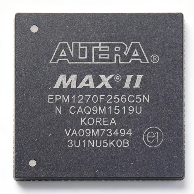
EPM1270F256 - MAX II 980-Macrocell CPLD, 256-BGA | Altera
The Altera (Intel PSG) EPM1270F256 is a member of the MAX II family of instant-on, non-volatile CPLDs, offering 980 typical equivalent macrocells (1270 LEs) in a 256-pin FineLine BGA package. According to the manufacturer datasheet, the device is built on a 0.18 µm process, operates from a 2.5 V / 3.3 V core supply, and supports user I/O up to 212 pins with a system frequency up to 201.1 MHz. It uses a non-volatile flash configuration cell that delivers instant-on functionality and eliminates external boot memory, simplifying board design in glue-logic and bus-interface applications. A CPLD (Complex Programmable Logic Device) is a non-volatile programmable logic device that combines the architectural simplicity, deterministic timing, and instant-on behavior of classic PAL/GAL logic with modern high-pin-count integration. Within the broader programmable-logic taxonomy, the MAX II family sits between simple 5-V SPLDs and high-density SRAM-based FPGAs: like SPLDs it is non-volatile and pin-configurable, but like an FPGA it integrates thousands of gates and dozens of I/O standards. MAX II devices are widely used as interface bridges, I/O expanders, and timing controllers in cost-sensitive industrial and consumer systems. Key features of the EPM1270F256 include 980 macrocells / 1270 logic elements, 8 Kbits of user flash memory, on-chip voltage regulators supporting 3.3 V, 2.5 V, 1.8 V, and 1.5 V operation, MultiVolt core and I/O supporting mixed-voltage interfacing, JTAG (IEEE 1149.1) boundary-scan programming, and an instant-on configuration time measured in microseconds. The 256-pin FineLine BGA footprint provides flexible I/O bank placement while preserving vertical migration to the EPM570 and EPM2210 in the same package. Architecturally, the EPM1270F256 implements the Logic Array Block (LAB) structure with 16 macrocells per LAB, a fast t<sub>PD</sub> in the single-digit nanosecond range, and a deterministic interconnect that makes it well-suited for I/O glue, address decoding, register insertion, and state-machine implementation. The non-volatile flash cell removes the need for a separate configuration PROM, lowering BOM cost and enabling secure in-system updates via JTAG. Typical applications include bus-interface bridging (e.g., PCI to local bus), I/O expansion and voltage translation, power-up sequencing logic, motor-control and industrial automation glue, LED display driving and refresh, and consumer-electronics control logic where instant-on behavior and low unit cost matter more than raw logic density. When designing with the EPM1270F256, ensure that the chosen I/O standard matches the bank's VCCIO supply and respect the device's MultiVolt I/O rules when bridging 1.5 V, 1.8 V, 2.5 V, and 3.3 V domains. Decoupling must follow the Quartus II power-pin guidance; leaving the on-chip regulator's decoupling incomplete can cause VCCINT ripple that degrades t<sub>PD</sub> margins. This page synthesizes distributor pricing, drop-in alternatives in the same 256-pin FineLine BGA footprint, and practical design notes drawn from the MAX II handbook to give engineers a single decision-ready view not found in the bare datasheet.

EPM1270F256C5 - MAX II 980 Macrocell CPLD | Altera / Intel | 256-FBGA
The Altera (now Intel) EPM1270F256C5 is a non-volatile, flash-based MAX II complex programmable logic device (CPLD) with 980 macrocells, 212 I/O pins, and a 6.2 ns pin-to-pin logic delay, housed in a 256-ball FineLine BGA package. It operates at 2.5 V/3.3 V core supply, supports 1.8 V, 2.5 V, 3.3 V and 5.0 V LVCMOS/LVTTL I/O standards through Altera MultiVolt core technology, and is built on a 0.18 µm TSMC process with on-chip flash configuration memory that makes the device instantly-on at power-up. What is a CPLD? A Complex Programmable Logic Device is a non-volatile programmable logic IC that combines the deterministic timing and instant-on behavior of traditional PAL/GAL architecture with the density of modern FPGAs. Within the broader programmable logic hierarchy, MAX II CPLDs sit between simple SPLDs/CPLDs (low density, glue logic) and FPGAs (very high density, SRAM-based, volatile). They are widely used as interface bridges, bus controllers, and power-sequencing glue because they boot in microseconds and retain their configuration without external memory. Key features of the EPM1270 include a 201.1 MHz internal operating frequency, support for JTAG (IEEE 1149.1) and in-system programmability (ISP) via the Altera ByteBlaster/USB-Blaster, an embedded User Flash Memory block for storing user data alongside the configuration, and a MultiVolt I/O ring that lets a single part interface with 1.8 V, 2.5 V, 3.3 V, and 5.0 V logic on the same PCB without level shifters. The 'C5' speed grade delivers 6.2 ns tPD with a commercial operating temperature range of 0 °C to +85 °C. Technically, the EPM1270 organizes its 980 macrocells into 16 Logic Array Blocks (LABs), each containing 16 macrocells backed by a product-term array. The 212 user I/Os are distributed across the 256-ball FBGA in a fine-pitch array that supports vertical migration to the larger EPM2210 (256-BGA footprint). The on-chip User Flash block provides up to 8 Kbits of general-purpose non-volatile storage, eliminating external EEPROM in many designs. Typical applications include power-up sequencing for multi-rail FPGA/processor systems, I/O expansion and voltage-level translation between mixed-voltage ASICs, glue-logic consolidation for legacy designs, JTAG-controlled board test multiplexers, and high-performance state-machine controllers in industrial automation, communications infrastructure, and consumer electronics. When designing with the EPM1270F256C5, observe the BGA routing rules (0.8 mm or 1.0 mm ball pitch depending on revision) and provide a clean 2.5 V/3.3 V supply because the core logic is not internally regulated. Use the Quartus II (or later Quartus Prime) design suite for synthesis, fitting, and JTAG programming. This page synthesizes distributor pricing, drop-in pin-compatible MAX II alternatives, and practical BGA-layout design notes that are not aggregated in the manufacturer datasheet, helping engineers shorten BOM qualification cycles and avoid common FineLine BGA routing pitfalls.
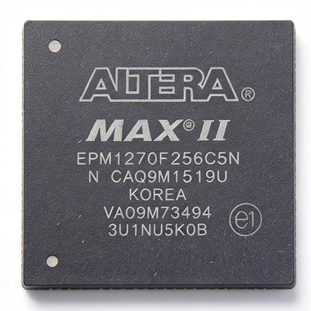
EPM1270F256C5N - MAX II 980-Macrocell CPLD | Intel | Altera
The Intel / Altera EPM1270F256C5N is a 980-macrocell, non-volatile, instant-on CPLD from the MAX II family, fabricated on a 0.18-µm process and housed in a 256-ball FineLine BGA package. It integrates 1270 logic elements, 980 macrocells, and 212 user I/O pins with a 6.2 ns pin-to-pin delay and a 201.1 MHz internal frequency. The device supports dual-voltage operation at 2.5 V / 3.3 V, making it compatible with both 2.5 V and 3.3 V logic families on the same board. The EPM1270F256C5N belongs to the MAX II family of instant-on, non-volatile CPLDs based on a 0.18-micron process and is supplied in a 256-FBGA tray. The 'N' suffix denotes a lead-free / Pb-free finish per industry lead-free marking conventions. A CPLD (Complex Programmable Logic Device) is a non-volatile programmable logic IC that combines AND/OR array-based macrocell architecture with on-chip flash configuration memory, providing instant-on behavior at power-up without an external boot ROM. Within the broader programmable logic hierarchy, CPLDs sit between small SPLDs/GALs and larger FPGAs, and are widely used as glue logic, I/O expanders, bus interface bridges, and power-up sequencers. MAX II CPLDs added low power consumption (multi-core architecture with internal flash) and integrated features such as user flash memory and a JTAG-based programming interface, making them a preferred choice for cost-sensitive control plane logic. Key features of the EPM1270F256C5N include non-volatile flash configuration for instant-on operation (no boot PROM required), 8 Kbits of user flash memory (per MAX II family), a JTAG-compliant IEEE 1149.1 boundary-scan / ISP interface, multi-voltage I/O support, and a chip-wide DEV_OE output enable pin. Multi-core architecture distributes logic across four logic regions, simplifying place-and-route for designs targeting fast pin-to-pin timing. Typical applications include I/O expansion and glue logic in 3.3 V and 2.5 V mixed-voltage systems, power-up sequencing for FPGAs and processors, JTAG-controlled bus bridges, address decoding for memory subsystems, and logic replacement for discrete 74-series TTL/MSI gates. The 256-FBGA package exposes 212 user I/O, allowing direct fan-out for dense parallel buses without external transceivers. When designing with this device, allocate sufficient PCB area for the 256-ball 1.0 mm pitch FBGA and follow Intel/Altera's reflow profile for lead-free BGA assembly. Use Quartus II software for HDL entry, synthesis, fitting, and timing closure; the same design can be retargeted across other MAX II family members with the same 256-pin footprint, simplifying board reuse. This page synthesizes distributor pricing, drop-in alternatives, and practical design notes not found in the manufacturer datasheet.
EPM1270F256I5 - 980-Macrocell MAX II CPLD, 256-FBGA | Altera
The Altera (Intel) EPM1270F256I5 is a MAX II family Complex Programmable Logic Device (CPLD) integrating 980 macrocells, 212 user I/O pins, and 8 Kbits of user flash memory in a 256-ball FineLine BGA (FBGA) package. It uses a 0.18 µm process and supports 2.5 V and 3.3 V I/O operation with 1.8 V core. The device provides a maximum internal operating frequency of approximately 201.1 MHz and a pin-to-pin propagation delay of approximately 6.2 ns. A CPLD (Complex Programmable Logic Device) is a non-volatile programmable logic device that combines multiple PAL/GAL-style macrocell blocks on a single chip with a global interconnect fabric. In the system hierarchy it sits between simple PLDs and FPGAs, offering instant-on non-volatile configuration, deterministic timing, and low power. MAX II specifically uses a Look-Up Table (LUT) based logic element, a flash-backed configuration cell, and a MultiTrack interconnect for predictable routing delays, making it a drop-in successor to legacy 5 V CPLDs. Key features of the EPM1270F256I5 include 980 logic elements, in-system programmability via JTAG, support for LVCMOS, LVTTL, PCI, SSTL-2, SSTL-3, and LVDS I/O standards, and an industrial temperature grade (-40 °C to +100 °C junction). The "I5" suffix denotes the industrial speed grade with tPD1 of 6.2 ns. The FBGA-256 package is surface-mount and provides high I/O density in a 17 mm × 17 mm footprint, making the device suitable for glue-logic and bus-interface consolidation where PCBs are constrained for space. Typical applications include I/O expansion and bridging in industrial controllers, power-sequencing and supervisory glue logic in telecom baseboards, bus decoding for legacy microprocessor interfaces, and configurable peripheral drivers. The instant-on behavior is particularly valuable in safety-critical or boot-time-sensitive systems that cannot tolerate FPGA configuration latency. Design consideration: the FBGA-256 package requires PCB design rules with 0.8 mm or 1.0 mm ball pitch, X-ray or rework-grade inspection for assembly, and at least four PCB layers for clean power/ground. Decoupling with 0.1 µF and 10 µF capacitors near each VCCIO/VCCINT ball is required. This page consolidates distributor pricing, drop-in same-family alternatives, and practical design guidance not found in the standalone MAX II datasheet.
EPM1270F256I5N - 980-Macrocell MAX II CPLD, 256-FBGA | Intel / Altera
The Intel / Altera EPM1270F256I5N is a 980-macrocell MAX II family Complex Programmable Logic Device (CPLD) housed in a 256-ball FineLine BGA (FBGA-256) package, built on a low-power 0.18-micron Flash-based process. It supports 212 user I/O pins, operates from 2.5 V / 3.3 V external supplies with 1.8 V core, and delivers 201.1 MHz maximum operating frequency with 6.2 ns pin-to-pin logic delay. The I5 speed grade combined with the -40C to +100C industrial temperature range makes this part suitable for demanding embedded control applications. A CPLD (Complex Programmable Logic Device) is a non-volatile programmable logic IC that sits between simple glue-logic PAL/GAL devices and larger FPGAs in the programmable logic hierarchy: CPLD -> programmable logic -> logic IC -> semiconductor. MAX II CPLDs use a unique MultiCore architecture pairing a LUT-based logic array with Flash configuration memory, providing instant-on behavior at power-up without external boot ROM - a key advantage over SRAM-based FPGAs in cost-sensitive and power-constrained designs. Key features include 980 macrocells (1270 logic elements), 8 Kbits user Flash memory, JTAG IEEE 1149.1 boundary-scan and in-system programmability via JTAG, MultiVolt I/O supporting 1.5 V, 1.8 V, 2.5 V, and 3.3 V interfaces, and a dedicated 3.3 V PCI-compliant I/O bank. The on-chip voltage regulator accepts a single 3.3 V supply and generates the internal core voltage, simplifying power tree design compared to legacy 5 V CPLDs. Typical applications include bus-interface bridging, I/O expansion and voltage-level translation, power-up sequencing logic, and glue-logic consolidation replacing multiple discrete PAL/GAL devices. The instant-on Flash architecture and industrial temperature range make EPM1270F256I5N especially common in telecom line cards, industrial controllers, and automotive infotainment subsystems where deterministic boot behavior is mandatory. When designing with this part, provide a minimum of four PCB layers with continuous ground and power planes for the FBGA-256 ball field, and use the Quartus II (or Quartus Prime Lite) design suite with a USB-Blaster or ByteBlaster for JTAG programming. Decoupling: place 0.1 uF ceramic capacitors within 50 mil of every VCCIO/VCCINT ball group, plus a 10 uF bulk cap near the supply pins. This page synthesizes distributor pricing, drop-in same-family MAX II alternatives, and practical FBGA-256 PCB design notes not collected in a single place in the original Altera datasheet.
EPM1270T144A5N - MAX II CPLD, 980 Macro Cells, 144-TQFP | Intel
The Intel (formerly Altera) EPM1270T144A5N is a MAX II family Complex Programmable Logic Device (CPLD) delivering 980 macro cells and 1270 logic elements in a 144-pin TQFP (T144) surface-mount package. It features a maximum propagation delay of 6.2 ns and supports internal supply voltages of 2.5 V and 3.3 V with an operating supply range of 2.375 V to 3.6 V, making it well-suited for low-power glue-logic and bus-interface bridging in 3.3 V systems. A CPLD (Complex Programmable Logic Device) is a non-volatile programmable logic device that combines multiple PAL-like macrocell arrays with a centralized interconnect matrix. It sits in the programmable logic hierarchy between simple SPLDs (e.g. PAL/GAL) and high-density FPGAs. CPLDs are valued for deterministic timing, instant-on behavior from on-chip Flash configuration memory, and high I/O-count pin flexibility. As part of the MAX II family, the EPM1270T144A5N targets high-volume cost-sensitive applications where instant-on logic and zero-configuration-time boot are essential. Key features include 116 user I/Os, 8 Kbits of embedded Flash user memory, JTAG (IEEE 1149.1) and in-system programmability via the Altera/Intel Quartus toolchain, and a wide -40C to +125C operating temperature range. The automotive-grade temperature suffix ("A5") indicates this part is rated for AEC-Q100-style harsh-environment use, though formal automotive qualification status should be confirmed against the latest Intel product folder. The EPM1270T144A5N uses a non-volatile Flash-based Look-Up Table (LUT) architecture with a global low-skew interconnect, providing predictable pin-to-pin delays that simplify multi-board timing closure. Compared with SRAM-based FPGAs it requires no external boot PROM and powers up ready-to-run, which is a decisive advantage in industrial control and automotive subsystem designs. Typical applications include I/O expansion and bus bridging, power-sequencing and reset-distribution logic, LED and display control, industrial sensor aggregation, automotive body and infotainment glue logic, and consumer electronics control planes. Designers should allocate JTAG pins (TCK/TMS/TDI/TDO) and decoupling capacitors per the MAX II handbook, and verify Quartus II/Quartus Prime support for the EPM1270 device symbol before commit.
EPM1270T144C3N - MAX II 1270 LE CPLD, 144-pin TQFP | Intel
The Intel (formerly Altera) EPM1270T144C3N is a low-power, non-volatile MAX II Complex Programmable Logic Device (CPLD) with 1270 logic elements, housed in a 144-pin TQFP package. Operating from a single 1.8 V core supply (VCCINT) with 3.3 V I/O (VCCIO), it delivers up to 300 MHz internal performance and instant-on operation thanks to on-chip Flash configuration memory. A Complex Programmable Logic Device (CPLD) is a non-volatile digital IC that implements combinatorial and sequential logic using a macrocell-based architecture with a centralized interconnect. CPLDs sit below FPGAs in the programmable logic hierarchy (CPLD -> PLD -> programmable logic -> digital IC), offering deterministic timing, instant-on configuration, and high drive strength ideal for glue logic, bus bridging, and power-up sequencing. Key features include 1270 logic elements (LEs), 980 equivalent macrocells, 8 Kbits of user Flash memory (UFM), 212 maximum user I/O pins, and MultiVolt I/O support for 1.5 V, 1.8 V, 2.5 V, 3.3 V interfaces. The device supports in-system programmability via IEEE 1149.1 JTAG and IEEE 1532, and offers 4-input look-up tables (LUTs) per logic element. Architecturally, the EPM1270 uses a classic MAX II LAB (Logic Array Block) structure with 16 macrocells per LAB, fast propagation delays (~3.6 ns pin-to-pin at -3 speed grade), and low standby current (~29 mA typical). The on-chip UFM supports up to 8 Kbits of non-volatile user storage, eliminating the need for external EEPROM for parameter storage. Typical applications include bus-interface bridging (e.g., 8/16/32-bit MCU-to-peripheral glue logic), power-up sequencing for FPGAs/ASICs, LED control and display driving, I/O expansion for microcontrollers, and replacement of multiple discrete 74-series logic gates. The wide MultiVolt I/O makes it ideal for mixed-voltage system designs. When designing with this device, evaluate total I/O count against the 212-pin maximum, and derate by at least 10% for routing flexibility. Always use the Quartus II or Intel Quartus Prime design software (free Web Edition) for synthesis, fitting, and JTAG programming. The T144 suffix denotes the 144-pin TQFP package; alternate package options (100-pin TQFP, 256-pin FineLine BGA) are available in the same EPM1270 die family. This page synthesizes distributor pricing, drop-in alternatives, and practical design notes not found in the manufacturer datasheet alone, providing engineers with a single reference for sourcing, replacement, and application guidance.
EPM1270T144C4N - MAX II CPLD 980 LE 144-TQFP | Intel / Altera
The Intel / Altera EPM1270T144C4N is a MAX II family Complex Programmable Logic Device (CPLD) delivering 980 logic elements (LEs) in a 144-pin TQFP package with 2.5 V / 3.3 V mixed-voltage I/O support and a 247.5 MHz internal core frequency. The "T144" suffix confirms the 144-pin TQFP plastic thin quad flat pack, the "C4" suffix denotes the commercial speed grade and 0.7 mm lead pitch, and the trailing "N" indicates a lead-free, RoHS-compliant assembly. A CPLD (Complex Programmable Logic Device) is a non-volatile, instantly-on programmable logic device that sits between a small FPGA and discrete glue logic in the system architecture hierarchy: CPLD -> programmable logic -> digital IC -> semiconductor. Unlike microcontrollers that execute sequential firmware, a CPLD runs parallel hardware state machines implemented in Look-Up Tables (LUTs) and macro cells, providing deterministic sub-nanosecond pin-to-pin propagation delays. MAX II devices in particular use a 1.8 V internal core with on-chip Flash configuration memory, eliminating the external boot PROM that legacy CPLDs required. Key features include 980 logic elements organized into 16 Logic Array Blocks (LABs), 80 user I/O pins, 8 Kbits of user Flash memory, on-chip voltage regulators supporting 3.3 V / 2.5 V / 1.8 V operation, JTAG IEEE 1149.1 boundary-scan support, and MultiVolt I/O allowing interfacing to 1.5 V, 1.8 V, 2.5 V, and 3.3 V logic without external level shifters. The MAX II architecture also embeds the Altera MultiTrack interconnect and delivers low dynamic power dissipation. Architecturally, MAX II combines LUT-based logic with a non-volatile Flash configuration cell so designs are always ready at power-up with no external boot device. The 144-TQFP package offers mature surface-mount assembly compatibility with conventional reflow profiles and supports vertical migration within the same package across the EPM570 / EPM1270 / EPM2210 density steps, allowing designers to scale logic capacity without changing PCB footprints. Typical applications include bus-bridging glue logic between processors and peripherals, I/O expansion for microcontrollers and ASICs, power-sequencing and reset distribution in multi-rail systems, configuration of FPGAs and memories, LED driving and display control, and protocol-bridging glue such as SPI-to-I2C or RGB-to-LVDS conversion. When designing with this device, leave at least 10% of logic resources unused to ease place-and-route and avoid timing closure issues. JTAG chain order must be planned carefully when the EPM1270T144C4N shares a scan chain with other boundary-scan devices, and unused I/O pins should be configured as outputs driving logic low rather than left floating. This page synthesizes distributor pricing, drop-in alternatives drawn from the MAX II family, and practical design notes not found in the manufacturer datasheet alone.
EPM1270T144C5N - MAX II CPLD, 980 LEs, 212 I/O, TQFP-144 | Intel/Altera
The Intel/Altera EPM1270T144C5N is a member of the MAX II family of Complex Programmable Logic Devices (CPLDs) delivering 980 Logic Elements (LEs), 980 macro cells, and up to 212 user I/Os in a 144-pin TQFP (T144) package. Built on a 0.18 µm flash-based process, it combines non-volatile configuration storage with low-power operation, providing instant-on functionality without an external boot PROM. The device is offered in the commercial 0 °C to +85 °C temperature range with a speed grade of -5. A CPLD (Complex Programmable Logic Device) is a non-volatile programmable logic device that sits between discrete glue logic and FPGAs in the programmable logic taxonomy. It uses a classic AND/OR PLA architecture with non-volatile flash cells, which means the configuration is retained across power cycles and the device begins operation within microseconds of power-up. The MAX II family specifically replaced Altera's legacy MAX 3000/7000 series by integrating flash configuration into the core, eliminating the need for an external configuration memory device and reducing total board cost and complexity. Key specifications include a maximum internal operating frequency of approximately 201.1 MHz, propagation delay (tPD) of 6.2 ns, a global clock network with up to 4 clocks per device, and supply voltage support for both 2.5 V and 3.3 V core/IO rails. The TQFP-144 package provides ample I/O for high-pin-count glue-logic applications, while JTAG (IEEE 1149.1) and in-system programmability via Altera/Quartus support simplified board-level bring-up and field upgrades. Typical applications include I/O expansion and bus bridging for microcontrollers, address decoding and glue logic in industrial control systems, power-sequencing and reset distribution, and LED-driving or display interface multiplexing. Because the configuration is non-volatile, the device operates without code shadowing or bootloader delay, making it well suited to deterministic boot-time applications. When designing with this part, account for I/O bank supply grouping (VCCIO banks) and ensure the Quartus II fitter report is reviewed to confirm pin assignment and timing closure before board sign-off.
EPM1270T144I5N - MAX II CPLD, 980 Macrocells, 144-TQFP | Intel
The Intel (formerly Altera) EPM1270T144I5N is a MAX II family Complex Programmable Logic Device (CPLD) delivering 980 macrocells and up to 212 user I/O pins, housed in a 144-pin TQFP (TQ) package. It operates at a core voltage of 2.5V/3.3V with multi-voltage I/O support (1.5V, 1.8V, 2.5V, 3.3V) and offers non-volatile Flash configuration memory with in-system programmability via JTAG. A CPLD (Complex Programmable Logic Device) is a non-volatile programmable logic device that sits between discrete glue logic and FPGAs in the programmable logic hierarchy. It provides instant-on operation, deterministic timing, and high-drive I/O for bus bridging, interface translation, and control-plane tasks. CPLDs belong to the broader family of programmable logic devices (PLDs), alongside FPGAs, and are commonly used as "glue logic" between processors, memory, and peripherals. Key features include 980 macrocells across 16 logic array blocks (LABs), 212 user I/Os, 8K bits of user Flash memory, and a maximum operating frequency of 201.1 MHz. The device provides multi-voltage I/O support, JTAG-based in-system programmability (ISP), and instant-on non-volatile operation. The industrial temperature range (-40C to +100C, "I" grade) and TQFP-144 package make it suitable for space-constrained, thermally-challenged designs. Architecturally, the MAX II family uses a low-power CMOS process with a uniform 4-input look-up table (LUT) architecture and a fast Global Clear signal. Unlike SRAM-based FPGAs, MAX II CPLDs require no external boot PROM and configure in microseconds, simplifying board layout and reducing BOM cost. Typical applications include I/O expansion and bus bridging for microcontrollers, power-up sequencing logic, peripheral interface glue logic (SPI, I2C, UART, parallel bus), and control-plane state machines in industrial and consumer systems. The combination of low cost, low power, and high I/O count also makes it attractive for prototype and small-volume production designs. Design considerations include thermal management for the 144-pin TQFP, I/O bank voltage planning (each bank can be powered independently to 1.5V/1.8V/2.5V/3.3V), and proper JTAG chain configuration. Quartus II software (or the free Quartus Prime Lite Edition) is required for design entry, synthesis, and programming. This page synthesizes distributor pricing, drop-in same-package alternatives, and practical design notes not found on the manufacturer datasheet alone, helping engineers select the optimal MAX II variant for their application.
EPM1270TI144C5N - 980 Macro Cell CPLD, MAX II, 144-TQFP | Intel
The Intel (formerly Altera) EPM1270TI144C5N is a non-volatile, flash-based Complex Programmable Logic Device (CPLD) from the MAX II family, delivering 980 macro cells, 212 user I/O pins, and a 6.2 ns pin-to-pin logic delay in a 144-pin TQFP package. It is built on a low-power 0.18 µm process and operates from a 2.5 V/3.3 V dual-voltage core/I/O supply, with internal flash configuration memory providing instant-on capability and eliminating the need for external boot ROM. The part is the industrial temperature range variant of the MAX II EPM1270, supporting -40 °C to +100 °C ambient operation. A CPLD (Complex Programmable Logic Device) is a non-volatile digital logic IC that combines the deterministic timing of PAL/GAL architecture with on-chip flash configuration memory, enabling glue-logic, bus-bridging, I/O expansion, and power-up state-machine functions without an external boot device. Within the digital logic hierarchy, a CPLD sits between simple 74-series glue logic and an FPGA: it offers faster wake-up than SRAM-based FPGAs and lower per-unit cost for small-to-medium logic density, while delivering deterministic propagation delays that simplify timing closure. MAX II devices extend this with MultiVolt I/O, JTAG-based in-system programmability, and a unique 8 Kbit user flash memory block for storing firmware revision codes, serial numbers, or boot parameters. Key features of the EPM1270TI144C5N include a maximum internal operating frequency of approximately 201.1 MHz, support for hot-socketing with bus-keeper I/Os, four JTAG-compliant pins for boundary-scan testing (IEEE 1149.1), MultiVolt core allowing the device to interface with 1.5 V, 1.8 V, 2.5 V, and 3.3 V logic without level shifters, and a built-in real-time in-system programmability feature that supports field upgrades. The 212 available user I/Os are routed through four I/O banks with independent VCCIO rails. Typical applications include I/O expansion and bus bridging in industrial controllers, power-up sequencing and reset logic for FPGA-based SoCs, peripheral interfacing in legacy equipment designs, and glue-logic replacement of multiple discrete 74-series TTL/CMOS parts. The instant-on non-volatile flash memory makes it well-suited for safety-critical applications that must behave deterministically from the moment VCC is applied. Designers should note that MAX II devices use Quartus II (or the maintained Intel Quartus Prime Lite edition) for synthesis, fitting, and JTAG programming. Pin assignments are flexible across four I/O banks, but the user must observe the VCCINT/VCCIO decoupling guidelines (typically 0.1 µF plus 10 µF bulk caps per bank) to meet the 6.2 ns tPD specification under full 212-I/O simultaneous-switching loads. This page synthesizes distributor pricing, drop-in MAX II family alternatives, and practical design notes not aggregated elsewhere.
EPM2210F256A5NGA - 2210 LE MAX II CPLD, 256-BGA | Intel
The Intel (Altera) EPM2210F256A5NGA is a MAX II family Complex Programmable Logic Device (CPLD) that delivers 2210 Logic Elements in a 256-ball FineLine BGA package, providing low-cost, non-volatile, low-power logic integration for glue-logic and I/O expansion designs. It features 1700 macrocells and 7 ns maximum pin-to-pin propagation delay per the manufacturer datasheet. The device targets applications where board space, instant-on non-volatility, and ultra-low standby power matter more than the highest logic density. A CPLD (Complex Programmable Logic Device) is a non-volatile programmable logic device that combines multiple PAL-like macrocell blocks on a single chip with a central interconnect. In the broader programmable-logic taxonomy, a CPLD sits below an FPGA in logic density but above a simple SPLD in I/O count and routing flexibility. MAX II devices are a specific Intel/Altera family that uses a 0.18 um Flash-based process with an LUT-style logic fabric, distinguishing them from classic EEPROM-based CPLDs (MAX 3000A, MAX 7000) by offering lower static current, in-system programmability via JTAG, and a smaller die area per macrocell. Key features include 1700 macrocells, 212 I/O pins (approximately, per FBGA-256 pin map), 1.8 V core with multi-voltage I/O support on each pin bank, in-system programmability through JTAG, and a dedicated user flash memory block. The part operates on a single 1.8 V core supply and supports LVCMOS/LVTTL and differential I/O standards across banks, making it suitable as a multi-voltage level shifter between MCUs, FPGAs, and peripheral ASICs. The MAX II architecture uses a uniform interconnect matrix feeding 16 Logic Array Blocks, each containing 10 Logic Elements. Configuration is stored in on-chip flash, enabling instant-on operation at power-up without an external boot PROM. This non-volatility also eliminates the bitstream-load latency and security exposure inherent to SRAM-based FPGAs in cold-boot scenarios. Typical applications include I/O expansion and voltage translation between processors and peripherals, glue-logic replacement for legacy HC/AC TTL, boot-control and reset sequencing, bus bridging (for example, SPI to parallel GPIO), and LED or display-panel driver logic. Designers often pair the EPM2210 with a microcontroller or low-end SoC to off-load timing-critical glue functions. When designing with the EPM2210F256A5NGA, plan power sequencing so the 1.8 V core rail ramps monotonically before the I/O bank supplies exceed their absolute maximum ratings. Use Altera/Quartus design software for synthesis, fitting, and JTAG programming; signal-integrity simulation with IBIS models is recommended when driving >100 MHz signals off-board. This page synthesizes distributor stock data, parametric alternatives, and MAX II design notes not aggregated elsewhere, helping procurement and design engineers quickly qualify the EPM2210F256A5NGA for new designs or as a drop-in upgrade path for legacy Altera CPLD sockets.

EPM2210F256C3N - MAX II CPLD 1700 Macrocells 7ns 256-FBGA | Intel
The Intel (formerly Altera) EPM2210F256C3N is a MAX II family Complex Programmable Logic Device (CPLD) delivering 1700 macrocells, 2210 logic elements, and 204 user I/Os in a 256-ball FineLine BGA package with a 7 ns maximum pin-to-pin propagation delay. It operates from internal 2.5V or 3.3V supplies, is in-system programmable via JTAG, and is rated for the commercial 0C to 85C operating junction temperature range. The MAX II architecture is built on a 0.18um flash-based process, providing instant-on non-volatile configuration that eliminates the external boot memory required by SRAM FPGAs. A CPLD (Complex Programmable Logic Device) is a non-volatile programmable logic device that combines multiple SPLD-like macrocell blocks on a single chip with a programmable interconnect matrix. In the system hierarchy it sits between simple SPLDs/PALs and full FPGAs: simpler than an FPGA (no boot PROM, deterministic timing), more capable than a SPLD (wider fan-in, more I/Os, more product terms). MAX II devices are positioned as low-cost, low-power glue-logic replacements for discrete 74-series logic and small FPGAs, and as I/O expanders for microcontrollers. Key features include 7 ns tPD (pin-to-pin), 304 MHz internal fMAX, JTAG-based IEEE 1149.1 in-system programmability, MultiVolt I/O supporting 1.5V/1.8V/2.5V/3.3V interfaces, an on-chip voltage regulator allowing single 3.3V supply operation, and zero standby current due to flash configuration. The FineLine BGA-256 package is shared vertically across the EPM570, EPM1270, and EPM2210 family, enabling PCB migration between densities. The MAX II architecture uses a Look-Up Table (LUT) + register macrocell, but unlike FPGAs the configuration is stored in on-chip flash rather than SRAM. This provides instant-on behavior at <100 us, deterministic timing (no jitter from configuration), and immunity to configuration bit upsets from radiation or noise. The device also embeds a User Flash Memory block (8 Kbits) accessible from the logic array for storing revision IDs or calibration constants. Typical applications include I/O expansion and bus bridging for microcontrollers, address decoding and glue logic in embedded systems, power-sequencing and reset-distribution networks, LED display multiplexing and industrial control front panels, and portable/battery-powered systems where the instant-on behavior and low standby power of the MAX II flash process deliver clear advantages over SRAM-based FPGAs. When designing with the EPM2210F256C3N, follow Altera/Intel MAX II hardware design guidelines: route JTAG TMS/TCK/TDO/TDI to a clean header, use a 100 ohm differential impedance for high-speed outputs, and provide adequate decoupling (100 nF + 10 uF per supply pin pair) near the BGA balls. This page synthesizes distributor pricing, drop-in MAX II family alternatives, and practical MAX II design notes not found in the manufacturer datasheet alone, helping engineers select and source the right CPLD density, speed grade, and temperature grade for their application.
EPM2210F256C4 - 2210 LE MAX II CPLD, 256-FBGA | Altera
The Altera (Intel) EPM2210F256C4 is a MAX II family Complex Programmable Logic Device (CPLD) that delivers 2,210 logic elements (equivalent to 1,700 macrocells) in a 256-ball FineLine BGA package. Built on a 0.18 µm six-layer-metal flash process, it provides non-volatile storage of configuration in 8 Kbits of on-chip flash memory, supporting instant-on behavior without an external boot PROM. The device operates across a 1.8 V core / 2.5 V or 3.3 V I/O MultiVolt interface, with commercial extended temperature grading. What is a CPLD? A Complex Programmable Logic Device is a non-volatile programmable logic IC that bridges the gap between discrete 74-series glue logic and FPGAs. CPLDs typically feature instant-on, deterministic timing, wide input gating, and modest logic density (hundreds to a few thousand macrocells). The MAX II architecture positions the family at the high-density end of the CPLD hierarchy: CPLD -> non-volatile programmable logic -> programmable logic IC -> digital semiconductor. The 'LE' (logic element) count is a vendor-specific unit; for MAX II, 1 LE ≈ 1.3 macrocells, which is why the 2,210-LE device is described as 1,700 macrocells. Key features include 1.8 V core supply with MultiVolt I/O supporting 1.5 V, 1.8 V, 2.5 V, and 3.3 V interfaces, an 8 Kbit User Flash Memory (UFM) block for non-logic data storage, JTAG-based in-system programmability (ISP), and 212 user I/O pins. The internal 7 ns pin-to-pin propagation delay (tPD1) supports glue-logic and bus-interface bridging at frequencies up to approximately 201 MHz. Typical applications include bus interface bridging, I/O expansion and voltage translation, power-up and power-sequencing control, configuration of larger FPGAs, and glue-logic replacement on industrial, telecom, and consumer motherboards. The UFM block additionally supports small-data EEPROM-style storage such as revision IDs, calibration tables, or boot parameters. When designing with the EPM2210F256C4, treat the 256-ball FineLine BGA as a fine-pitch package and follow standard BGA PCB design rules: microvia or via-in-pad recommended, matched-length impedance for high-speed edges, and proper thermal relief for the center balls that sit beneath the die. Quartus II (or the current Quartus Prime Lite) is the supported design entry and programming toolchain. This page synthesizes distributor pricing, drop-in alternatives within the same MAX II family, and practical design notes not found in the manufacturer datasheet alone.
EPM2210F256C4N - 2210 LE MAX II CPLD 256-FBGA | Intel / Altera
The Intel (formerly Altera) EPM2210F256C4N is a MAX II family Complex Programmable Logic Device (CPLD) integrating 2,210 Logic Elements (LEs), 1,700 macro cells, and 204 Kbits of user flash memory into a 256-ball FineLine BGA (FBGA) package. Built on a 0.18 µm process, it offers a maximum internal operating frequency of 247.5 MHz, a pin-to-pin propagation delay of 7.0 ns, and supports I/O standards including 3.3-V LVTTL/LVCMOS, 2.5-V LVTTL/LVCMOS, 1.8-V LVTTL/LVCMOS, 1.5-V LVCMOS, and PCI up to 66 MHz. The device is supplied by a 3.3 V core / I/O rail and operates over the commercial 0 °C to +85 °C temperature range. A Complex Programmable Logic Device (CPLD) is a non-volatile, instant-on programmable logic IC that combines multiple PAL/GAL-like macro-cell arrays with a global interconnect fabric. It belongs to the broader class of programmable logic devices (PLD), which also includes FPGAs; CPLDs are distinguished by deterministic timing, low static power, and flash-based configuration that eliminates external boot memory. Within the MAX II family, the EPM2210 is the highest-density member, positioning it between small glue-logic CPLDs and entry-level FPGAs. Key features include four global clock networks with up to four clock pins, a JTAG-compliant IEEE Std. 1149.1 boundary-scan interface with in-system programmability (ISP), 8 Kbits of user flash memory, MultiVolt I/O for mixed-voltage interfacing, and on-chip support for 32-bit, 66-MHz PCI. The 256-ball FineLine BGA package is pin-compatible with EPM570F256 and EPM1270F256 devices, enabling vertical density migration without PCB rework. The EPM2210F256C4N is widely used as a bus-bridging glue-logic replacement, an I/O expansion controller for microcontrollers, a power-up sequencer for multi-rail systems, and a low-density state-machine engine in industrial, consumer, and automotive subsystems. Designers favor the MAX II family for its instant-on non-volatile behavior, predictable timing, and Quartus Prime Lite design-flow support. When integrating this part, ensure 1.2 V, 2.5 V, and 3.3 V supplies are decoupled with 0.1 µF and 10 µF capacitors placed within 100 mils of each ball. Maintain continuous reference planes beneath the BGA and follow Altera's JTAG chain guidelines for in-system programming. This page synthesizes distributor pricing, drop-in same-package alternatives, and practical MAX II design notes not aggregated in any single manufacturer datasheet.
EPM2210F256C5 - MAX II CPLD 1700 Macrocells 201MHz FBGA-256 | Altera / Intel
The Altera / Intel EPM2210F256C5 is a MAX II family Complex Programmable Logic Device (CPLD) offering 1700 macrocells, 201.1 MHz maximum internal frequency, and a 256-ball FineLine BGA (FBGA-256) package. It is fabricated on a 0.18 µm flash-based process and supports both 2.5 V and 3.3 V operation, making it a flexible glue-logic replacement for multiple discrete SSI/MSI parts. A CPLD (Complex Programmable Logic Device) is a non-volatile, flash-programmable logic device that sits between simple SPLDs and FPGAs in the programmable logic hierarchy: SPLD -> CPLD -> FPGA -> Programmable Logic. MAX II devices are particularly valued for their instant-on (no boot PROM required), ultra-low standby current, and high I/O count, and they are commonly used for I/O expansion, bus bridging, and power-up sequencing in designs that also include an FPGA, ASIC, or microprocessor. Key features of the EPM2210F256C5 include 1700 logic elements (macrocells), 272 user I/Os, instant-on non-volatile configuration stored in on-chip flash, in-system programmability via JTAG (IEEE 1149.1), and a MultiVolt core allowing I/O bank operation from 1.5 V to 3.3 V. The device supports commercial-grade operating temperature 0C to +85C (C5 suffix) and vertical migration within the 256-ball FBGA package alongside the smaller EPM570F256 and EPM1270F256 devices. Architecturally, the EPM2210F256 uses Altera's classic Lab/Expander-matrix interconnect feeding Logic Array Blocks (LABs) of 16 macrocells each, with each macrocell containing a programmable flipflop and a wide sum-of-products engine. Combined with the on-chip User Flash Memory (UFM) block, this enables system designers to store board parameters, serial numbers, or boot configuration without an external EEPROM. The 201 MHz fMAX is derived from a 5 ns internal propagation delay and is typical for the C5 speed grade. Typical applications include I/O expansion and level translation between legacy 5 V/3.3 V peripherals and modern processors, FPGA I/O bank expansion, board-level glue logic replacement, bus protocol bridging (e.g., SPI to parallel), power-rail sequencing at system start-up, and embedded control where deterministic propagation delay matters more than raw throughput. When designing with the EPM2210F256C5, leave a generous copper pour under the exposed thermal pad (if any), ensure all JTAG signals (TCK, TMS, TDI, TDO) are pulled to defined logic states, and verify VCCINT and VCCIO decoupling with 0.1 µF capacitors placed as close to each supply pin as possible. The C5 commercial speed grade is not interchangeable with C3/C4/I4/I5 grades without recompiling the design. This page synthesizes distributor pricing, MAX II drop-in alternatives, vertical-migration guidance, and practical design notes not found in the bare Altera datasheet - useful for BOM managers and hardware engineers evaluating legacy MAX II designs.