製品 (39,000+)

M2GL150-FCVG484I - IGLOO2 146K LE FPGA 484-BGA | Microchip
M2GL150-FCVG484I

M2GL150-FCVG484I - IGLOO2 146K LE FPGA 484-BGA | Microchip

The Microchip Technology M2GL150-FCVG484I is a 146,124-logic-element IGLOO2 low-power flash-based Field-Programmable Gate Array (FPGA) integrated circuit housed in a 484-ball Fine-pitch Ball Grid Array (FBGA, 19x19 mm) package with 248 user I/O. Built on a 1.2 V core, 65 nm flash process, the device combines up to 5,120 Kbits of embedded SRAM, 240 Math Blocks (18x18 multipliers), 4 PLLs and DLLs, and 1.2 Gbps SERDES capability, addressing low-density logic integration and high-speed serial bridging without an external MCU. An FPGA (Field-Programmable Gate Array) is a semiconductor device built around an array of configurable logic blocks (CLBs) connected by programmable interconnect, allowing designers to customize digital functions after fabrication. FPGAs sit in the hierarchy: programmable logic -> logic IC -> integrated circuit -> semiconductor. The IGLOO2 family specifically targets low-power operation with flash-based configuration cells that retain bitstream in silicon without external boot memory, simplifying board design and improving security. Key features include 512 Kbits of embedded non-volatile memory (eNVM), 64 KB embedded SRAM (eSRAM), high-performance DDR2/DDR3/LPDDR memory controller interfaces with ECC, integrated DSP through the Math Block array, and an ARM Cortex-M3 hard processor subsystem variant (M2GL150S). The I/O count of 248 supports wide parallel interfaces for video bridging, industrial control and communications aggregation. The flash-based architecture provides instant-on capability and inherent security against bitstream read-back, advantages over SRAM-based FPGAs that require external boot PROMs. From a technical depth perspective, the M2GL150 uses a 4-input LUT fabric with dedicated carry chains and distributed control logic, providing a fine-grained architecture suitable for glue logic, bus bridging and signal conditioning. The 65 nm low-power process node enables sub-microamp sleep currents and flexible power modes that suit battery-powered and industrial always-on applications. Typical applications include industrial control planes, secure communications bridges, motor control and I/O expansion, video/image processing, and low-power system management. The flash-based non-volatile configuration makes the device particularly attractive for safety-critical and secure systems requiring deterministic boot and tamper resistance. When designing, ensure the PCB layout accommodates the 484-ball FBGA 19x19 mm land pattern with controlled-impedance traces for SERDES lanes and matched-length DDR routing for memory interfaces. Heat dissipation is generally low due to flash-based operation, but core utilization above 70 percent may require thermal analysis. This page synthesizes distributor pricing, drop-in alternatives, and practical design notes not found in the manufacturer datasheet.

見積もり お問い合わせ
M2S010-TQG144 - SmartFusion2 SoC FPGA 12K LE 166MHz | Microchip
M2S010-TQG144

M2S010-TQG144 - SmartFusion2 SoC FPGA 12K LE 166MHz | Microchip

The Microchip Technology M2S010-TQG144 is a SmartFusion2 System-on-Chip (SoC) FPGA integrating a 166 MHz ARM Cortex-M3 hard processor subsystem with a flash-based FPGA fabric of approximately 12,000 logic elements (10K logic modules / 12KLEs), housed in a 144-pin TQFP package (20x20 mm). The device combines deterministic FPGA logic, an embedded microcontroller, and advanced security features on a single low-power 65 nm process die, targeting secure connectivity, industrial control, and general-purpose I/O expansion designs. A SmartFusion2 SoC FPGA is a heterogeneous computing device that fuses a hard ARM Cortex-M3 processor core, on-chip SRAM and eNVM, debug peripherals, and a reprogrammable FPGA fabric in one package. This integration removes the inter-chip communication latency of a discrete MCU-plus-FPGA design and simplifies the PCB by collapsing what would otherwise be a multi-chip system onto a single 144-TQFP footprint. M2S010 sits at the low-density end of the SmartFusion2 family, with larger siblings (M2S025, M2S050, M2S060, M2S150) scaling up logic and memory. Key features of M2S010-TQG144 include 12KLEs / 12084 cells of flash-based FPGA fabric, a 166 MHz ARM Cortex-M3 subsystem, on-chip 512 KB eNVM and 64 KB SRAM, embedded DDR controllers, multiple high-speed serial transceivers, and hardware cryptographic accelerators for AES, SHA, and ECC. The device operates from a 1.2 V core supply and supports industrial temperature grades, with low static and dynamic power consumption enabled by flash-based non-volatile configuration cells. Typical applications include industrial motor control, secure IoT edge nodes, communications bridging, system management controllers, and PCI Express endpoint designs. The integrated ARM Cortex-M3 allows designers to host control-plane firmware on-chip while the FPGA fabric handles high-bandwidth data-plane logic, data acquisition, or custom peripheral glue logic.

見積もり お問い合わせ
M2S025-VFG400I - SmartFusion2 SoC FPGA, 25K LE, Cortex-M3 | Microchip
M2S025-VFG400I

M2S025-VFG400I - SmartFusion2 SoC FPGA, 25K LE, Cortex-M3 | Microchip

The Microchip Technology M2S025-VFG400I is a SmartFusion2 System-on-Chip (SoC) FPGA integrating a 25K-logic-element flash-based FPGA fabric with a hard ARM Cortex-M3 microcontroller subsystem running at 166 MHz, housed in a 400-ball VFBGA (17x17 mm) package. Built on a low-power 65 nm flash process, the device delivers approximately 27,696 logic cells, embedded SRAM, DSP blocks, and high-speed serial transceivers while embedding the deterministic ARM Cortex-M3 processor alongside programmable analog. A System-on-Chip (SoC) FPGA is an integrated device that combines a programmable logic fabric with one or more fixed processor cores and, in many families, programmable analog. The hierarchy places SoC FPGA under FPGA & CPLD and alongside conventional microcontroller units. SmartFusion2 specifically integrates a flash FPGA, a deterministic Cortex-M3 hard processor, and an analog compute engine, allowing designers to consolidate what previously required a microcontroller, an FPGA, and a separate ADC-plus-front-end chip onto a single die. Key features of the M2S025 include 43 kbits of embedded SRAM, dedicated DSP blocks, multi-standard SERDES, on-chip user flash, hard Cortex-M3 with 1.6 DMIPS/MHz core performance, and integrated analog-to-digital converters. The -I suffix indicates an industrial temperature grade of -40C to +100C, and the device operates from a 1.2 V core supply with separate PLL and I/O banks. Architecturally, SmartFusion2 uses a 4-input LUT fabric with built-in fracturable DSP and dedicated high-speed SERDES blocks for protocols like PCIe Gen2 and SGMII. The hard Cortex-M3 subsystem includes tightly-coupled SRAM, mpu, and an AHB-Lite matrix that exposes the FPGA fabric as memory-mapped peripherals, providing deterministic real-time interrupt response for industrial control. Typical applications include industrial motor control and motor drive stages, secure communications, general-purpose I/O expansion for industrial PCs and embedded boards, portable instrumentation, and avionics-grade embedded control. Because the M2S025 integrates both programmable analog and digital fabric, it is particularly well suited to mixed-signal acquisition designs. When using the M2S025, plan the PCB layout around the 1 mm pitch BGA with matched-length routing for SERDES lanes and dedicated decoupling per bank. Use Libero SoC design software for place-and-route, and verify pinout against DS0115 since pin tables have been split from the main datasheet.

見積もり お問い合わせ
M2S060TS-FGG484 - SmartFusion2 SoC FPGA 60K LE ARM Cortex-M3 | Microchip
M2S060TS-FGG484

M2S060TS-FGG484 - SmartFusion2 SoC FPGA 60K LE ARM Cortex-M3 | Microchip

The Microchip Technology M2S060TS-FGG484 is a SmartFusion2 System-on-Chip (SoC) FPGA that integrates an ARM Cortex-M3 hard processor subsystem with 60K logic element (LE) FPGA fabric in a 484-pin FPBGA (FGG484) 23x23 mm package. The device operates at up to 166 MHz on the MCU subsystem and is fabricated on a 65 nm low-power process node with 1.2 V core operation. A SmartFusion2 SoC FPGA is a heterogeneous platform that combines a deterministic microcontroller subsystem with programmable logic on a single die. The Cortex-M3 subsystem includes embedded SRAM, real-time clock, and a complete peripheral set, while the FPGA fabric provides flexible custom logic, DSP blocks, and high-speed SERDES. This integration eliminates inter-chip buses, reduces board area, and provides hardware-software co-design capability for safety-critical and mixed-signal designs. Key features include 60K logic elements (56.5K LEs per Mouser listing), embedded ARM Cortex-M3 with up to 166 MHz operation, 484-pin FPBGA package with 23x23 mm body, 65 nm flash-based process technology, integrated PCIe and Gigabit Ethernet hardening, and low-power operation suitable for industrial and secure applications. The device is rated for extended industrial temperature ranges and includes hardware cryptographic accelerators for secure boot, AES, and RSA. Architecturally, the SoC combines a flash-based FPGA fabric (no external configuration PROM required) with a hardened MCU subsystem, providing instant-on behavior and deterministic interrupt latency. SERDES lanes support up to 1 Gbps data communication, and the device integrates 4 MB of user flash and 64 KB of eNVM for secure key storage. Typical applications include industrial control and motor drives, secure communications gateways, PCIe endpoint bridging, video/image processing, IoT edge nodes, and avionics system management. The SmartFusion2 family's low power and security features make it suitable for defense, medical, and industrial automation designs. When designing with the M2S060TS-FGG484, observe the device's maximum supported I/O toggle rate and derate accordingly for industrial temperature operation. Plan PCB layout to keep SERDES lane lengths matched within the tolerance specified in the datasheet, and provide adequate decoupling for the multiple supply rails (1.2 V core, 2.5 V/3.3 V auxiliary). This page synthesizes distributor pricing, drop-in SmartFusion2 alternatives, and practical PCB design notes not found in the manufacturer datasheet.

見積もり お問い合わせ
M30281F6 - 16-bit M16C MCU 48KB Flash 24MHz 64-LQFP | Renesas
M30281F6

M30281F6 - 16-bit M16C MCU 48KB Flash 24MHz 64-LQFP | Renesas

The Renesas M30281F6 (M30281F6HP#U5B variant) is a 16-bit single-chip microcomputer belonging to the M16C/Tiny Series of the M16C Family, housed in a 64-pin LQFP package. It integrates 48KB of Flash program memory, 4KB of RAM, and operates from a 3.0V to 5.5V supply with a maximum CPU clock of 24MHz, targeting automotive and industrial embedded control applications. The M16C architecture uses a CISC instruction set and includes an internal oscillator, on-chip debug, multiple timers, a 10-bit A/D converter, and a rich set of serial interfaces (UART, I2C, SSI). Built on Renesas' mature M16C/Tiny platform, it offers low power consumption, high code density (RISC-like code efficiency despite CISC ISA), and excellent EMI/ESD immunity. A microcontroller (MCU) is a single-chip computer containing a CPU core, program memory (Flash/ROM), working memory (RAM), and a programmable set of peripherals such as timers, communication controllers, and analog interfaces. The M16C family sits in the 16-bit microcontroller hierarchy: MCU -> 16-bit MCU -> CISC MCU -> M16C architecture -> M16C/Tiny Series. Compared to 8-bit MCUs, 16-bit parts like the M30281F6 deliver higher arithmetic precision and richer peripherals; compared to 32-bit ARM Cortex-M parts, M16C offers smaller code size per function and lower cost at equivalent peripheral counts. Key differentiating features of the M30281F6 include the M16C CISC core with multi-cycle instruction execution that maximizes Flash efficiency, 55 programmable I/O pins, an internal oscillator that eliminates external clock components, and automotive-grade qualification of the underlying silicon process. The device supports up to 20MHz external oscillator input and offers sleep/stop low-power modes critical for battery-powered or automotive quiescent-current designs. Typical applications include automotive body controllers (BCM, lighting modules, mirror/door/window controllers), HVAC fan/valve controllers, small industrial sensor signal conditioners, white-goods control boards, and consumer devices that benefit from 16-bit math, large Flash, and 5V-tolerant I/O. The wide 3V-5.5V supply range lets designers use the same part across 3.3V and legacy 5V systems without level shifters. When designing with this MCU, ensure your toolchain supports the M16C core (Renesas NC30/WF, IAR M16C, or KPIT GNU); pin-compatible alternatives are typically other M3028x family members. A common design pitfall is exceeding the 5.5V absolute-maximum on any pin, which can permanently damage the part. This page consolidates distributor pricing, drop-in pin-compatible alternatives, and design notes that go beyond the manufacturer datasheet, giving engineers a faster path to qualification and second-source decisions.

見積もり お問い合わせ
M30281F6HP#U3B - 16-bit 20MHz M16C/Tiny MCU 48KB Flash | Renesas
M30281F6HP#U3B

M30281F6HP#U3B - 16-bit 20MHz M16C/Tiny MCU 48KB Flash | Renesas

The Renesas Electronics M30281F6HP#U3B is a 16-bit single-chip microcontroller from the M16C/60 M16C/Tiny/28 series, providing 48 KB of Flash program memory, 4 KB of RAM, and 55 I/O pins. The device operates from a 2.7 V to 5.5 V supply and runs at a 20 MHz internal oscillator speed. It is housed in a 64-pin LQFP package (64-LFQFP, 10x10 mm). A microcontroller (MCU) is a single integrated circuit containing a CPU core, memory, and programmable peripherals designed for embedded control. The M16C family belongs to the CISC (Complex Instruction Set Computer) class of 16-bit microcontrollers and is part of Renesas's M16C/Tiny sub-series optimized for low-power industrial and consumer applications. The M16C/Tiny architecture is a streamlined variant of the full M16C/60 platform and sits within the broader Renesas MCU hierarchy: M16C/Tiny -> M16C/60 -> M16C -> 16-bit MCU -> embedded microcontroller. Key features of the M30281F6HP#U3B include 48 KB Flash with 4 KB on-chip RAM, an internal oscillator, a 10-bit A/D converter, multiple timers, and a variety of serial interfaces (UART, I2C-bus-compatible, SPI). The 55 I/O lines support extensive peripheral integration. Industrial temperature grade (-40C to +85C) and Pb-free packaging suit factory and appliance designs requiring long-term reliability. The architecture uses an enhanced M16C CPU core that delivers deterministic interrupt response, low power consumption, and a rich instruction set with signed multiply/divide. Built-in power management modes, including HALT and STOP, enable low standby current for battery or energy-constrained designs. Typical applications include industrial control (PLCs, inverters, motor drivers), home appliances (washing machines, microwave ovens, air conditioners), office automation (printers, scanners), and automotive body electronics. The wide 2.7 V to 5.5 V operating range simplifies integration with both 3.3 V and 5 V sensors and actuators. When designing with this MCU, allocate sufficient decoupling (0.1 uF plus bulk) near each VCC/VSS pair, and reserve the dedicated oscillator pins for an external crystal if higher timing accuracy is required. Designers should also budget Flash endurance of 100 erase/write cycles minimum. This page synthesizes distributor pricing, drop-in alternatives, and practical design notes for the M30281F6HP#U3B that are not found in the manufacturer datasheet alone, supporting faster component selection and BOM decisions.

見積もり お問い合わせ
M30281F6HP#U5B - 16-Bit M16C/Tiny MCU, 48KB Flash | Renesas
M30281F6HP#U5B

M30281F6HP#U5B - 16-Bit M16C/Tiny MCU, 48KB Flash | Renesas

The Renesas M30281F6HP#U5B is a 16-bit CISC microcontroller from the M16C/60 family (M16C/Tiny series, group 28) running at 20 MHz, with 48KB on-chip Flash and 4KB RAM, housed in a 64-pin LQFP (PLQP0064KB-A) package measuring 10x10 mm. It operates from a single 2.7 V to 5.5 V supply, supports 55 programmable I/O lines, and integrates an internal oscillator plus a 3-phase PWM timer, 16-bit timers, an IEBus controller, and a 10-bit A/D converter. A microcontroller (MCU) is a single-chip computer that integrates a CPU core, program and data memory, peripherals, and I/O into one package. The M16C family is a 16-bit CISC architecture originally developed by Mitsubishi Electric and now maintained by Renesas. Within the broader taxonomy, MCUs sit inside the semiconductor hierarchy as programmable logic devices, distinct from fixed-function ASICs. The M16C/Tiny sub-family emphasizes low power consumption, high code density (compact instruction set), and a wide operating voltage range suitable for both 3.3 V and 5 V designs. Key features of the M30281F6HP#U5B include 48 KB of Flash program memory, 4 KB of RAM, an internal oscillator that eliminates external clock hardware in cost-sensitive designs, and 55 I/O pins for moderate peripheral integration. Built-in peripherals include a 3-phase PWM timer for motor control, an IEBus (Inter-Equipment Bus) controller for in-vehicle networking, multiple 16-bit timers, and a 10-bit ADC. The wide 2.7 V to 5.5 V supply range lets the same part serve 3.3 V logic and legacy 5 V analog subsystems. Typical applications for the M30281F6HP#U5B include automotive body controllers (door modules, mirror control, wiper control), small appliance motor drivers (fan, pump, small BLDC), industrial sensor signal conditioners, and HVAC actuator controllers. The 3-phase PWM output is particularly useful for sensorless or hall-sensor brushless DC motor drives where deterministic real-time response is needed. When designing with this MCU, allocate the 48 KB Flash budget for application code plus a small bootloader, leaving 4 KB of RAM for stack, heap, and peripheral buffers. Use the internal oscillator for BOM savings but switch to an external crystal when CAN or UART timing accuracy is required. The IEBus peripheral requires proper bus arbitration and termination per the IEBus standard. This page synthesizes distributor stock, parametric position within the M16C family, and design notes not collected in the manufacturer datasheet alone, helping engineers evaluate the M30281F6HP#U5B for both new designs and legacy M16C platform migrations.

見積もり お問い合わせ
M30281F6HP#U9B - 16-bit M16C/Tiny MCU 48KB Flash 64-LQFP | Renesas
M30281F6HP#U9B

M30281F6HP#U9B - 16-bit M16C/Tiny MCU 48KB Flash 64-LQFP | Renesas

The Renesas Electronics M30281F6HP#U9B is a 16-bit single-chip microcontroller from the M16C family, M16C/Tiny/28 series, delivering 20 MHz CPU performance with 48 KB of on-chip flash program memory and 4 KB of RAM in a 64-pin LQFP package. The device operates from 3 V to 5 V supplies (3/5 V dual-supply compatible) and provides 55 general-purpose I/O lines, internal oscillator, and on-chip peripherals including timers, serial interfaces, A/D converter, and a DMA controller suitable for automotive and industrial embedded applications. A microcontroller (MCU) is a single-chip computer containing a processor core, program memory (Flash/ROM), working memory (RAM), and peripheral blocks such as timers, communication controllers, and analog interfaces. 16-bit microcontrollers occupy the middle ground between 8-bit entry-level MCUs and 32-bit ARM Cortex devices, delivering higher code density, native handling of larger data types, and richer peripherals while keeping cost and power modest. The M16C/Tiny series uses the R8C CISC core, which provides a compact 16-bit instruction set with high code density. Key features include 48 KB flash memory organized as 48K × 8, 4 KB RAM organized as 4K × 8, an internal oscillator, 55 programmable I/O pins, and an operating temperature range of -20 °C to +85 °C. The 64-LQFP (10 × 10 mm) package offers a compact footprint while providing ample I/O for embedded designs. The MCU supports low-power operation modes to extend battery life in portable systems. The M16C architecture uses a Harvard-style internal bus with separate instruction and data paths, which improves throughput versus single-bus designs at the same clock rate. The integrated flash memory supports in-circuit programming via a serial interface, simplifying firmware updates in production and in the field. Built-in safety features include a watchdog timer, voltage detection circuits, and clock monitors. Typical applications include automotive body electronics, HVAC control modules, white-goods motor control, sensor interface boards, and small consumer appliances. The wide 3 V to 5 V supply range also supports industrial 5 V backplane systems. The internal oscillator reduces BOM cost by removing external crystals in cost-sensitive designs. When designing with this MCU, ensure the firmware update procedure leaves the M16C/Tiny/28 vector table in a consistent state during flash writes. Decoupling capacitors must be placed close to all VCC/AVCC pins, and unused I/O pins should be configured as outputs with defined levels to minimize power consumption. Designers should verify the package's thermal performance when driving multiple high-current loads. This page consolidates verified distributor pricing, same-package alternatives, and practical design notes that go beyond the manufacturer datasheet summary, giving engineers a one-stop reference for selecting and sourcing the M30281F6HP#U9B.

見積もり お問い合わせ
M30624FGPFP - 16-Bit 24MHz 256KB MCU | Renesas | 100-QFP
M30624FGPFP

M30624FGPFP - 16-Bit 24MHz 256KB MCU | Renesas | 100-QFP

Renesas Electronics M30624FGPFP is a 16-bit CMOS microcontroller in the M16C/60 and M16C/62P families, operating at up to 24 MHz with 256 KB of flash memory in a 100-pin QFP package measuring 14 x 20 mm. It uses Renesas Technology's high-performance silicon-gate CMOS process and the M16C/60 Series CPU core. A microcontroller is a programmable system-on-chip that integrates a CPU core, memory, timers, serial interfaces, analog peripherals, and I/O into one package. The M16C/62P architecture combines a 16-bit instruction set with sophisticated, efficient instructions, supporting embedded control in industrial, consumer, communications, and appliance equipment. The verified distributor listing identifies the MCU as operating at 3/5 V. Key verified attributes include a 16-bit CPU, 24 MHz maximum operating frequency, 256 KB organized as 256K x 8 flash memory, and a 100-QFP package. A lead-free M30624FGPFP#U5C ordering variant is listed by Mouser. The exact RAM capacity, peripheral complement, timer channels, ADC characteristics, operating-temperature range, and I/O ratings were not supplied in the verified source data and require confirmation from the manufacturer datasheet. Technically, the part belongs to the M16C/60 family using the M16C/60 Series CPU core. Its 16-bit architecture is relevant to control loops and embedded workloads requiring more arithmetic capability than a basic 8-bit MCU. The 256 KB flash capacity provides substantially more on-chip program storage than many small 8-bit controllers. The 100-QFP format offers a high pin count, potentially supporting dedicated peripheral and general-purpose I/O, but exact signal assignment must be taken from the datasheet rather than inferred. Typical application categories include industrial controllers, factory equipment, motor and machine control, communications equipment, test and measurement instruments, and consumer appliances. These uses align with the MCU category and high-pin-count package, although the manufacturer datasheet should be checked for specific peripheral support before design selection. Design planning must account for the 3/5 V supply indication, programming requirements, oscillator and reset circuitry, decoupling, and all 100 physical pins. Firmware migration is especially important because Renesas directs new-system designs toward M3062LFGPFP rather than the older M30624FGPFP. Review current lifecycle status and obtain authoritative technical support before committing a new production design. This page consolidates verified distributor specifications, the manufacturer migration notice, and engineering-oriented replacement guidance. It separates confirmed values from missing data so engineers can make an informed sourcing decision without treating incomplete search snippets as full datasheet specifications.

見積もり お問い合わせ
M30624FGPFP#U3C - 16-Bit 24MHz 256KB Flash MCU 100-QFP | Renesas
M30624FGPFP#U3C

M30624FGPFP#U3C - 16-Bit 24MHz 256KB Flash MCU 100-QFP | Renesas

The Renesas Electronics M30624FGPFP#U3C is a 16-bit single-chip CMOS microcomputer from the M16C/60 platform, specifically the M16C/62P sub-family, packaged in a 100-pin QFP (14x20 mm). The device integrates an M16C/60 Series CPU core running at up to 24 MHz with 256 KB of on-chip FLASH program memory (256K x 8) and is specified for 3 V / 5 V dual-voltage operation across the industrial temperature range (-40 °C to +85 °C I-temp). What is a 16-bit microcontroller (MCU)? A microcontroller is a single integrated circuit that combines a CPU core, program memory (ROM/FLASH), working memory (RAM), and programmable peripherals on one die. The M16C/60 family belongs to the 16-bit CISC MCU category - sitting hierarchically between 8-bit legacy controllers (8051, PIC16) and modern 32-bit ARM Cortex-M cores - and is widely used in industrial, automotive body, and white-goods applications where deterministic interrupt response, low EMI, and code density matter more than raw MIPS. Key features of the M30624FGPFP include the high-performance M16C/60 series CPU core with a small, position-independent instruction set, 12 KB of RAM, multi-channel 10-bit A/D converter, multiple timers, UART/SIO/I2C interfaces, watchdog timer, and rich interrupt controller. The 'U3C' suffix indicates the Pb-free I-temp lead-free 100-QFP packaging variant. The 256 KB flash is field-programmable via standard serial programming and supports block-erase plus byte-write operations. The silicon gate CMOS process yields low power consumption, with multiple idle/sleep modes and a power-down halt state suitable for battery-aware designs. The M16C architecture is engineered for C code efficiency and fast context switches, supported by a uniform 16-bit register file and orthogonally addressed peripherals. Typical applications include industrial motor control, factory automation sensor nodes, HVAC control boards, automotive body ECUs (non-safety), consumer white goods, and general-purpose embedded control replacing 8-bit MCUs where more code space or analog integration is needed. It is often paired with external EEPROM for parameter storage and CAN/LIN transceivers for vehicle networking. When designing with this device, route the analog supply (AVCC) separately from the digital supply and decouple with 0.1 µF + 10 µF bulk capacitors near each supply pin. Use the on-chip debugger interface for development and ensure XIN/XOUT traces are short to avoid oscillator noise coupling. The 100-QFP package supports hand-soldering and rework, simplifying prototyping. This page synthesizes distributor pricing, drop-in same-family alternatives, and practical design notes not found in the manufacturer datasheet - giving engineers a faster procurement and design-in path for the M16C/62P family.

見積もり お問い合わせ
M30624FGPFP#U5C - M16C/62P 16-bit MCU, 256KB Flash, 100-QFP | Renesas
M30624FGPFP#U5C

M30624FGPFP#U5C - M16C/62P 16-bit MCU, 256KB Flash, 100-QFP | Renesas

The Renesas Electronics M30624FGPFP#U5C is a single-chip 16-bit CMOS microcomputer from the M16C/60 Series M16C/62P Group, integrating 256 KB of flash memory and 24 MHz of CPU performance in a 100-pin QFP (14x20 mm) package. It combines the high-performance M16C/60 CPU core with the silicon-gate CMOS process, delivering 16-bit processing at low power consumption for embedded control applications. A microcontroller (MCU) is an integrated circuit that combines a CPU, memory (RAM/ROM/Flash), and programmable I/O peripherals on a single silicon die. The M16C family sits within the 16-bit microcontroller taxonomy, between 8-bit MCUs (e.g., 8051) and 32-bit ARM Cortex-M devices, offering a balance of code density, deterministic interrupt latency, and peripheral integration well suited to real-time control. The M16C/62P Group sits under the M16C/60 Series umbrella of Renesas's mid-range MCU portfolio. Key features include 256 KB of on-chip flash (256K x 8), 4 KB of on-chip RAM, a 24 MHz maximum CPU clock, a 10-bit A/D converter, a wide operating voltage range of 2.7V to 5.5V, and an operating temperature range of -20C to +85C. The 100-QFP package provides ample I/O for motor control, automotive body electronics, and industrial automation. Multiple timers, serial interfaces (UART, I2C, SPI), and interrupt controllers are integrated, eliminating the need for external peripherals. The M16C/60 CPU core uses a register-based architecture with 24-bit linear addressing, supporting high-level language efficiency and rich addressing modes. Built-in flash allows in-application reprogramming via serial or background programming modes, simplifying field firmware updates. The silicon-gate CMOS process yields low quiescent current and supports 3V and 5V system designs with a single part number. Typical applications include industrial motor control, HVAC control boards, automotive body ECUs, home appliance controllers (washing machines, microwave ovens), and metering/pump controllers. The wide 2.7V-5.5V supply range makes it suitable for both 3.3V and 5V logic designs. When designing with this MCU, ensure the 100-pin QFP footprint matches your PCB land pattern and provide adequate decoupling (100 nF + 10 uF) near each power pin. Use the on-chip debug/flash programming interface for production firmware loading rather than relying on external programmers. Note that Renesas recommends the newer M3062LFGPFP for new designs. This page consolidates distributor pricing, drop-in alternative analysis, and practical design notes beyond what the manufacturer datasheet alone provides.

見積もり お問い合わせ
M30626FHPFP - 16-Bit 24MHz M16C/62P MCU, 384KB Flash | Renesas
M30626FHPFP

M30626FHPFP - 16-Bit 24MHz M16C/62P MCU, 384KB Flash | Renesas

The Renesas M30626FHPFP is a 16-bit single-chip CMOS microcontroller from the M16C/62P family, built around the high-performance M16C/60 Series CPU core with 384KB of on-chip flash memory and 24MHz maximum operating frequency, housed in a 100-pin QFP (14x20 mm) package. It supports 5V operation with a wide 2.7V to 5.5V supply range, integrates 31KB of RAM, and provides rich on-chip peripherals including multi-channel 10-bit A/D converter, DMA controller, three UART/SIO channels, and timers. An M16C/62P microcontroller is a 16-bit CISC MCU from the M16C family of single-chip microcomputers, engineered using high-performance silicon-gate CMOS process technology. It sits within the broader taxonomy of microcontroller -> embedded processor -> semiconductor IC, and is designed for industrial-grade control applications requiring deterministic real-time response, low EMI, and a robust instruction set optimized for C compiler code density. Key differentiating features include 384KB flash program memory (384K x 8 organization), 31KB RAM, 87 I/O pins, four DMA channels, three serial I/O blocks, 8-bit and 16-bit timers, a 10-bit A/D converter with up to 26 input channels, and a watchdog timer. It supports both 3V and 5V operation (industrial temperature range -40C to +85C) and is Pb-free, RoHS-compliant. The device implements the M16C/60 CPU core with 16-bit fixed instruction width, register-based architecture with 32KB address space, and efficient C-language support. Its integrated peripherals include CRC calculation hardware, intelligent I/O ports capable of key input wake-up, and a power-saving mode with multiple clock gearing options. The architecture enables deterministic interrupt latency for real-time control. Typical applications include industrial automation controllers, motor control inverters, factory automation PLCs, building HVAC controls, security system panels, vending machine controllers, and white goods control boards. The wide operating voltage (2.7V-5.5V) and industrial temperature range (-40C to +85C) make it suited to harsh environments. Design consideration: when migrating from earlier M16C/62 to M16C/62P, verify the watchdog timer and A/D converter channel mapping. Place a 0.1uF decoupling capacitor adjacent to each VCC/AVCC pin pair and keep the analog reference traces short to minimize digital switching noise on ADC sampling accuracy. This page synthesizes distributor pricing from DigiKey/Mouser, drop-in alternatives in the same 100-QFP package, and practical design notes that complement the manufacturer datasheet with field-application guidance.

見積もり お問い合わせ
M30855FJGP#U3 - 16/32-Bit M32C/85 MCU, 512KB Flash, 144-LQFP | Renesas
M30855FJGP#U3

M30855FJGP#U3 - 16/32-Bit M32C/85 MCU, 512KB Flash, 144-LQFP | Renesas

The Renesas M30855FJGP#U3 is a 16/32-bit single-chip CMOS microcontroller from the M32C/80 series (M32C/85 group) operating at up to 32 MHz, integrating 512 KB of on-chip flash program memory and 24 KB of RAM in a 144-pin LFQFP (20x20 mm) package. The part is specified over an industrial temperature range of -40C to +85C and operates from a 3 V to 5.5 V supply, making it compatible with both 3.3 V and 5 V system designs. The M30855FJGP#U3 offers 121 general-purpose I/O pins, multiple on-chip peripherals including timers, serial interfaces (UART/SIO/I2C), an A/D converter, and DMA channels for high-throughput embedded control. A microcontroller (MCU) is a self-contained computing subsystem that integrates a CPU core, program and data memory, peripherals, and I/O on a single silicon die. Within the broader semiconductor taxonomy, MCUs belong to the integrated circuits family, specifically the microcontroller subcategory, and sit below microprocessors in complexity while providing complete embedded-control functionality. The M32C/80 platform is Renesas' legacy 16-bit CISC architecture with 32-bit internal registers, popular in industrial automation, automotive body controllers, and consumer appliances. Key features of the M30855FJGP#U3 include 512 KB flash program memory (512K x 8), 24 KB of RAM (24K x 8), a maximum operating frequency of 32 MHz, an internal oscillator, and 121 user I/O pins routed through the 144-LFQFP package. The wide 3 V to 5.5 V supply range simplifies integration into both legacy 5 V designs and modern 3.3 V subsystems without level shifters, while the industrial temperature grade enables deployment in factory, automotive cabin, and outdoor equipment. The M32C/85 core architecture uses a CISC instruction set optimized for compact code density, with hardware multipliers, multiple register banks, and a rich interrupt controller that supports real-time control loops. The integrated DMA reduces CPU load for high-speed peripheral transactions such as serial communication and A/D conversion. Typical applications for the M30855FJGP#U3 include industrial factory automation systems, automotive body electronics, consumer appliance control boards, and general-purpose 16-bit embedded platforms. Engineers select this part for designs that require a mature, well-supported Renesas M16C/M32C software ecosystem. When designing with the M30855FJGP#U3, ensure that the chosen emulator/debugger (such as the E8a or E10A-USB) matches the device group, and follow the M32C/85 hardware manual pin-function assignment tables to avoid peripheral conflicts on the 121 I/O pins. This page synthesizes verified distributor pricing, drop-in alternative MPNs from the Renesas M16C/M32C family, and practical design notes not consolidated on any single manufacturer page.

見積もり お問い合わせ
M321R4GA0PB2-CCP - 32GB DDR5-6400 ECC RDIMM | Samsung
M321R4GA0PB2-CCP

M321R4GA0PB2-CCP - 32GB DDR5-6400 ECC RDIMM | Samsung

The Samsung M321R4GA0PB2-CCP is a 32GB DDR5-6400 ECC registered DIMM (RDIMM) operating at 6400 MT/s (PC5-51200) on a 1.1V supply, packaged as a 288-pin DIMM in a 1Rx4 single-rank x4 configuration. A registered DIMM (RDIMM) is a server memory module that buffers the address and command signals through a register chip before they reach the DRAM devices. This buffering reduces the electrical load on the memory controller, enabling higher module counts per channel and greater total capacity in servers and workstations. RDIMMs sit within the DDR5 SDRAM module hierarchy: DRAM device -> FBGA-packaged die -> registered DIMM -> memory subsystem, and they differ from LRDIMMs (which buffer data as well) and UDIMMs (which have no buffering). Key features of the M321R4GA0PB2-CCP include 32GB capacity organized as 4G x 72 (including 8 bits of ECC per 64-bit word), DDR5-6400 operation at CL52 latency, on-die ECC plus side-band ECC checking, and 1.1V operation aligned with the JEDEC DDR5 standard for reduced power per bit versus DDR4. The module uses twenty 4G x 4 DDR5 DRAM devices in FBGA packages, giving a single-rank x4 topology that the memory controller addresses as one rank. Technically, DDR5 moves the power management from the motherboard to an on-module PMIC (12V to 1.1V conversion), improving signal integrity and power efficiency. Dual 32-bit sub-channels per module improve effective bandwidth and reduce contention. The -CCP speed bin denotes the 6400 MT/s grade, delivering 51.2 GB/s peak bandwidth per channel pair. Typical applications include enterprise servers, edge compute nodes, low virtual-machine-density hosts, workstations, and general-purpose data center platforms from Dell PowerEdge, HPE ProLiant, Lenovo ThinkSystem, and Supermicro using Intel Xeon or AMD EPYC processors with DDR5 memory controllers. A key design consideration: RDIMMs must only be mixed with other RDIMMs of the same generation on a channel; they cannot be combined with UDIMMs or LRDIMMs, and maximum supported speed depends on the CPU memory controller and populated channel configuration. This page synthesizes distributor pricing and availability data, JEDEC-compliant drop-in alternatives from multiple vendors, and practical deployment notes not consolidated in the manufacturer documentation.

見積もり お問い合わせ
M321R4GA3EB0-CWM - 32GB DDR5-5600 ECC RDIMM | Samsung
M321R4GA3EB0-CWM

M321R4GA3EB0-CWM - 32GB DDR5-5600 ECC RDIMM | Samsung

The Samsung M321R4GA3EB0-CWM is a 32GB DDR5-5600 ECC Registered DIMM (RDIMM) operating at 1.1V with CL46 latency, housed in a 288-pin DIMM form factor. This dual-rank x8 (2Rx8) module delivers PC5-44800 bandwidth and is organized as 4Gx72 with twenty FBGA-packaged 2Gx8 DDR5 DRAM devices plus a registering clock driver for server-grade reliability. A Registered DIMM (RDIMM) is a server memory module that buffers address and command signals through a registering clock driver (RCD), reducing electrical load on the memory controller and enabling higher capacities and densities than unbuffered UDIMMs. RDIMMs sit within the DDR5 SDRAM family, which itself belongs to the broader category of volatile DRAM memory used in servers, workstations, and enterprise storage. ECC (Error Correcting Code) functionality detects and corrects single-bit memory errors, which is essential for data integrity in 24/7 datacenter operation. Key features include DDR5-5600 data rate (PC5-44800), 32GB capacity in a dual-rank configuration that balances density and signal integrity, 1.1V operation that lowers power draw versus DDR4's 1.2V, and on-module ECC registered architecture. DDR5's on-die ECC, bank grouping, and dual 32-bit subchannels per DIMM improve effective bandwidth and reliability at speed. Technically, the module uses 20 pieces of 2Gx8 FBGA DDR5 DRAM across two ranks, with a registering clock driver managing command/address traffic. The x72-wide data path (64-bit data plus 8 bits of ECC-style check bandwidth) supports the RDIMM error-handling architecture. Typical applications include Dell PowerEdge C6620, MX760c, R660, and R660xs servers (OEM cross-reference Dell P8XPW), edge compute nodes, low-VM-density hosts, and general-purpose virtualization platforms that list DDR5-5600 RDIMMs on their qualified vendor list. Design consideration: always verify module presence against the server platform's Qualified Vendor List (QVL), since RDIMM speed may train down if the platform only supports lower DDR5 rates. This page synthesizes distributor pricing, drop-in alternatives, and platform compatibility data not consolidated in the manufacturer datasheet.

見積もり お問い合わせ
M321R8GA0EB2-CWM - 64GB DDR5-5600 ECC RDIMM | Samsung
M321R8GA0EB2-CWM

M321R8GA0EB2-CWM - 64GB DDR5-5600 ECC RDIMM | Samsung

The Samsung M321R8GA0EB2-CWM is a 64GB DDR5-5600 ECC registered DIMM (RDIMM) with dual-rank x4 (2Rx4) organization, operating at 1.1V on a 288-pin DIMM module built with Samsung D-die DRAM devices in a (4G x 4) x 40 composition. Registered (buffered) DIMMs are a class of server memory modules in which address, command, and control signals pass through a register chip before reaching the DRAM devices. This buffering reduces the electrical load on the memory controller, allowing servers and workstations to populate more DIMM slots per channel than is possible with unbuffered (UDIMM) memory. RDIMMs sit within the memory module hierarchy: DDR5 SDRAM device -> registered DIMM -> server memory -> enterprise datacenter memory subsystem. On-die ECC plus registered operation makes them mandatory in most multi-socket x86 server platforms. Key features of the M321R8GA0EB2-CWM include 5600 MT/s data rate (2800 MHz clock, PC5-44800 bandwidth class), CAS latency of CL46 at the rated speed, dual-rank x4 organization that improves server memory capacity scaling, and 1.1V operation that lowers power draw versus DDR4 RDIMMs running at 1.2V. The DDR5 architecture also moves the power management IC (PMIC) onto the module and introduces two independent 32-bit subchannels per module, improving memory bandwidth efficiency for multi-core CPUs. Technically, the module uses Samsung D-die 4G x 4 DDR5 DRAM components, 40 of which compose the 64GB (8G x 72 including ECC bits) registered module. The x4 device width combined with registered operation supports strong RAS (reliability, availability, serviceability) characteristics demanded in virtualization and database environments. On-die ECC detects and corrects single-bit errors internal to each DRAM die, while the registered interface maintains signal integrity at high slot counts. Typical applications include Dell PowerEdge, HPE ProLiant, Lenovo ThinkSystem, and Supermicro server platforms, as well as virtualization hosts, in-memory databases, and AI inference servers requiring high-capacity registered memory. Multiple identical modules should be installed in matched sets for optimal multi-channel bandwidth. When designing or upgrading, confirm platform BIOS support for DDR5-5600 RDIMMs, as many platforms default to lower speeds such as 4800 MT/s or 5200 MT/s depending on populated DIMMs per channel. Mixing module speeds causes all modules to run at the slowest common speed. This page synthesizes verified distributor specifications, drop-in alternatives, pricing context, and practical deployment notes not consolidated in the manufacturer datasheet.

USD $2,826.92 お問い合わせ
M321RYGA0PB2-CCP - 96GB DDR5-6400 ECC RDIMM | Samsung
M321RYGA0PB2-CCP

M321RYGA0PB2-CCP - 96GB DDR5-6400 ECC RDIMM | Samsung

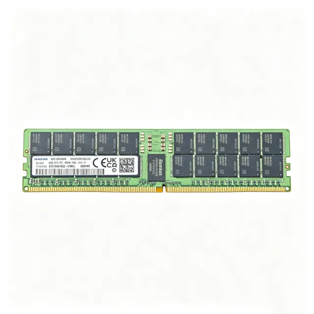
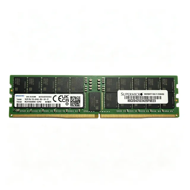
The Samsung M321RYGA0PB2-CCP is a 96 GB DDR5-6400 ECC Registered DIMM (RDIMM) server memory module rated at 6400 MT/s (PC5-51200) with 1.1 V nominal operation, organized as 2Rx4 (dual-rank, x4 DRAM) in a 288-pin RDIMM form factor. It is built from 40 FBGA 6Gx4 DDR5 DRAM devices and delivers a 72-bit ECC data path (12GX72 organization) for enterprise servers and workstations. A Registered DIMM (RDIMM) is a server memory module that places a register (RCD) and data buffers between the DRAM devices and the memory controller, reducing electrical load on the command/address bus and enabling higher module densities and higher speeds than unbuffered DIMMs. Within the memory hierarchy, an RDIMM sits above UDIMM and SODIMM in capacity and reliability, and below LRDIMM in load reduction; it is the mainstream choice for two-socket and four-socket x86 servers. DDR5 adds on-module PMIC power management, on-die ECC, and two 32-bit subchannels per module. Key features of the M321RYGA0PB2-CCP include 96 GB capacity in a single module, 6400 MT/s transfer rate, 2Rx4 organization for maximum rank-level interleaving, ECC Registered operation for data integrity, and 1.1 V DDR5 standard voltage. The 96 GB density is achieved with non-binary 24 Gb DDR5 DRAM dies, allowing high capacity without the cost of 3DS stacking. Technically, the module uses 40 FBGA 6Gx4 DRAM packages arranged in two ranks of twenty devices each, with a 288-pin edge connector and a 72-bit ECC data path. The on-module PMIC and SPD hub are part of the JEDEC DDR5 RDIMM architecture, and the module is 100% JEDEC compliant per distributor documentation. Typical applications include enterprise rack servers, virtualization hosts, in-memory databases, and high-performance workstations where 96 GB per DIMM enables dense configurations. The 2Rx4 organization and ECC RDIMM design suit memory-bandwidth-bound workloads such as AI inference, analytics, and VDI. When designing or upgrading, verify that the server platform supports 24 Gb non-binary DDR5 DRAM and 96 GB RDIMM densities, and populate DIMMs per the vendor's population rules to maintain rated 6400 MT/s speed. This page synthesizes distributor pricing, drop-in alternatives, and practical design notes not found in the manufacturer datasheet.

USD $3,445.31 在庫あり
M41T65Q6F - Serial RTC with Alarm, I2C, 1.3V-3.6V | STMicroelectronics
M41T65Q6F

M41T65Q6F - Serial RTC with Alarm, I2C, 1.3V-3.6V | STMicroelectronics

The STMicroelectronics M41T65Q6F is a serial access real-time clock (RTC) integrated circuit with alarm functions, providing a complete Clock/Calendar function plus 32.768 kHz output in a 16-pin VQFN exposed-pad package. The device communicates through a 400 kHz I2C (2-wire serial) interface, operates from 1.3 V to 3.6 V supply, and integrates memory-mapped registers for seconds, minutes, hours, day, date, month, year, and century tracking with automatic leap-year compensation through the year 2100. A Real-Time Clock (RTC) is a category of low-power timing IC that maintains accurate wall-clock time and date information independent of the system microcontroller. RTCs are essential components in any battery-backed system that must preserve time-of-day across power cycles. The M41T65 belongs to the RTC IC > Clock/Calendar > I2C RTC sub-family, and within ST's product hierarchy it sits under Timekeeping ICs > Serial RTC > RTC with Alarms. RTCs bridge the gap between digital logic and physical time by using a 32.768 kHz crystal oscillator as the time-base reference and counting oscillator cycles to derive seconds, minutes, hours, and calendar days. Key features of the M41T65Q6F include a wide operating voltage range of 1.3 V to 3.6 V (suitable for direct battery backup operation), integrated alarm and interrupt functions, a programmable square-wave output derived from the 32.768 kHz crystal, low power consumption typically below 1 microamp in battery backup mode, and an automatic backup switchover when VCC falls below a defined threshold. The 16-pin VQFN-EP (QFN-16) exposed-pad package provides low thermal resistance for stable operation across the -40 °C to +85 °C industrial temperature range and supports automated PCB assembly. Architecturally, the M41T65Q6F combines a 32.768 kHz crystal oscillator, frequency divider chain, BCD-coded time/date registers, I2C interface logic, alarm comparators, and a trickle charger circuit. The internal oscillator drives a divider that produces 1-second resolution. Time and date are stored in Binary-Coded Decimal (BCD) format for direct display compatibility. The integrated trickle charger allows the device to recharge an external backup supercapacitor or rechargeable battery when main power is present, then automatically switch over to backup supply on VCC failure. Typical applications include metering and data-logging systems, industrial controllers requiring time-stamped events, point-of-sale (POS) terminals, medical devices needing scheduled dosing or data recording, consumer electronics with calendar/alarm functions, and any battery-backed embedded system that needs to wake the host MCU at scheduled times. The low 1.3 V minimum supply also makes the M41T65Q6F well-suited for single-cell battery systems. When designing with the M41T65Q6F, ensure the 32.768 kHz crystal load capacitance matches the datasheet specification (typically 12.5 pF) and place the crystal traces as short and symmetric as possible to minimize parasitic capacitance. A decoupling capacitor of 0.1 microfarad should be placed within 2 mm of the VCC pin. The exposed pad (EP) must be soldered to the ground plane for mechanical and thermal reliability. This page synthesizes distributor pricing, package-equivalent alternatives in the same ST M41Txx RTC family, and practical design notes not aggregated on the manufacturer datasheet PDF.

見積もり お問い合わせ
M41T81SM6F - Serial RTC 2.7-5.5V I2C 8-SOIC | STMicroelectronics
M41T81SM6F

M41T81SM6F - Serial RTC 2.7-5.5V I2C 8-SOIC | STMicroelectronics

The STMicroelectronics M41T81SM6F is a low-power serial real-time clock (RTC) with a built-in 32.768 kHz external-crystal-controlled oscillator, supplied in an 8-pin SOIC (SO-8) surface-mount package. It operates from 2.7 V to 5.5 V, communicates over a 400 kHz I2C (2-wire) serial interface, and provides a 64-byte BCD-formatted clock/calendar register map covering tenths/hundredths of seconds through century. A Real-Time Clock (RTC) is a dedicated integrated circuit that keeps track of wall-clock time even when the main system is powered down. RTCs sit at the bottom of the timekeeping hierarchy: RTC -> clock/calendar IC -> clock and timing -> semiconductor. They are essential wherever a system must maintain accurate time/date stamping across power cycles, such as data loggers, metering equipment, and industrial controllers. The M41T81S is one of the few RTCs that integrates both the 32.768 kHz crystal interface and the compensation circuitry in a single 8-pin package, reducing BOM and board area. Key features include 2.7 V to 5.5 V single-supply operation, low typical current consumption for battery-backed operation, programmable alarm and watchdog functions, automatic leap-year compensation through year 2099, and a software clock calibration function that can compensate crystal aging in 5 ppm steps. The I2C slave address is fixed at 0x68 with the A0 pin grounded. Internally, the M41T81S combines an external 32.768 kHz crystal oscillator circuit with a binary-coded decimal (BCD) counter chain. Eight bytes of on-chip SRAM back the clock/calendar registers and are accessed via the standard I2C protocol. The device supports both 100 kHz Standard-mode and 400 kHz Fast-mode I2C, making it compatible with most microcontroller families. The byte-wide register map follows the ST M41Txx family convention for drop-in software portability. Typical applications include industrial automation controllers, point-of-sale terminals, metering (electricity/water/gas), data loggers, medical devices requiring timestamped events, automotive telematics and infotainment subsystems, security and access-control panels, and any battery-backed embedded system needing persistent wall-clock time. When designing with the M41T81SM6F, place the 32.768 kHz crystal within 5 mm of the OSCIN/OSCOUT pins and guard those traces with a ground ring to minimize stray capacitance. Provide a backup battery (typically a 3 V coin cell) on VCC with a series Schottky or Schottky-plus-resistor OR-ing network so the RTC domain remains powered during main-rail outages. Use 100 nF decoupling close to VCC and observe the I2C pull-up sizing rules for the chosen bus speed. This page consolidates distributor pricing, parametric drop-in alternatives, and practical layout notes that complement the manufacturer datasheet, giving engineers a single reference for sourcing and designing in the M41T81SM6F.

見積もり お問い合わせ
M41T82RM6F - Low-Power I2C RTC with 32.768 kHz | STMicroelectronics
M41T82RM6F

M41T82RM6F - Low-Power I2C RTC with 32.768 kHz | STMicroelectronics

The STMicroelectronics M41T82RM6F is a low-power serial I2C real-time clock and calendar with a built-in 32.768 kHz oscillator, a 7-bit register address format, and an 8-pin SOIC package measuring 3.90 mm wide. It operates from a 2.0 V to 5.5 V clock supply range and provides battery-backed timekeeping with an ultra-low battery supply current of 365 nA. The device is designed for systems that require accurate calendar time, programmable alarms, periodic events, and low standby power. A real-time clock is a specialized timekeeping integrated circuit that maintains seconds, minutes, hours, date, day, month, and year information even when the main system is unpowered. The RTC category sits within clock and timing semiconductors, where crystal-based oscillators, dividers, registers, and digital interfaces work together to provide a stable time reference. Unlike a software timer, an RTC can continue counting through power loss and can be read again when the host processor restarts. The M41T82RM6F combines an external-crystal-controlled oscillator architecture with low-power serial communication. Its programmable alarm and timer functions can wake a connected microcontroller or signal that a scheduled interval has elapsed. The I2C interface reduces wiring requirements in compact embedded systems, while the 2.0 V to 5.5 V operating range supports both low-voltage and conventional supply environments. The 365 nA battery supply current is especially relevant for battery-backed meters, industrial recorders, and portable instruments. The STMicroelectronics M41T82 family description identifies the SO8 version as using an external 32.768 kHz crystal. Accurate timekeeping therefore depends not only on the RTC electronics but also on crystal selection, load-capacitance matching, layout quality, and temperature behavior. The M41T82RM6F is suited to data loggers, access-control terminals, metering equipment, industrial controllers, and consumer products requiring persistent timestamps. Its low standby consumption helps reduce energy use when the main supply is absent. For a robust design, place the RTC and its crystal close together on the PCB, keep high-current switching paths away from the oscillator network, and provide the required bypass capacitance. Confirm the exact pin functions, register behavior, alarm polarity, and electrical limits against the manufacturer datasheet before layout release. The verified source data supports the component identity, package, interface, oscillator, supply range, and low-current claims; additional operating details remain subject to the full STMicroelectronics datasheet. This page combines verified manufacturer and distributor information with application guidance, comparison fields, and design notes. It is intended to help engineers identify whether the M41T82RM6F fits a low-power battery-backed timekeeping design while distinguishing verified facts from parameters requiring confirmation from the latest datasheet.

見積もり お問い合わせ
M41T94MQ6F - Serial RTC 44B NVRAM SPI 16-SOIC | STMicroelectronics
M41T94MQ6F

M41T94MQ6F - Serial RTC 44B NVRAM SPI 16-SOIC | STMicroelectronics

The STMicroelectronics M41T94MQ6F is a serial real-time clock (RTC) with 44 bytes of NVRAM and a RESET output, packaged in a 16-pin SOIC (0.154", 3.90 mm width). It provides a complete clock/calendar function with tenths/hundredths of seconds, seconds, minutes, hours, day, date, month, year, and century counters, and communicates with the host MCU through a 4-wire SPI bus at clock rates up to 2 MHz. The internal 32,768 Hz oscillator integrates 12.5 pF of load capacitance, allowing direct connection of an external tuning fork crystal without external load capacitors while still tolerating high crystal series resistance (up to 80 kΩ typical). A real-time clock (RTC) is a low-power integrated circuit that maintains accurate wall-clock time using a quartz crystal reference, even when the main system is powered down. RTCs sit within the broader hierarchy of clock-and-timing ICs, which include general-purpose timers, oscillators, and PLL/clock generators. Unlike MCU-internal time counters, dedicated RTC ICs add battery backup switchover, calendar logic, and non-volatile user memory that survives both system reset and loss of main supply. Key features of the M41T94MQ6F include SPI serial interface, 44 bytes of battery-backed NVRAM (16 bytes general-purpose plus 8 bytes used by the clock/calendar), a RESET output pin that asserts a fixed-duration low pulse for system brown-out management, and an integrated 32 kHz oscillator with on-chip load capacitance. The device operates from 2.7 V to 5.5 V main supply and is specified for the industrial -40 °C to +85 °C temperature range. Typical applications include metering (electricity/water/gas), point-of-sale terminals, data loggers, industrial controllers, and any embedded system that needs a tamper-resistant, battery-backed time stamp separate from the application MCU. Designers should add a lithium backup cell (or supercapacitor) to the VBAT pin and follow the crystal-layout guidance in the ST datasheet for long-term timekeeping accuracy.

見積もり お問い合わせ
M471A2G43AB2-CWE - 16GB DDR4-3200 SO-DIMM | Samsung
M471A2G43AB2-CWE

M471A2G43AB2-CWE - 16GB DDR4-3200 SO-DIMM | Samsung

The Samsung M471A2G43AB2-CWE is a 16 GB unbuffered non-ECC DDR4 SO-DIMM module rated at 3200 MT/s (PC4-25600), organised as a single 1x16 GB rank in the industry-standard 260-pin SO-DIMM form factor used in laptops, mini-PCs, and small-form-factor systems. A SO-DIMM (Small Outline Dual In-Memory Module) is a compact JEDEC-standard memory module derived from the full-size DIMM but roughly half the height. DDR4 SDRAM is the fourth generation of double data rate synchronous DRAM; it operates at lower voltage (1.2 V) than DDR3 (1.5 V), reaches higher per-pin data rates up to 3200 MT/s at launch, and uses a 288/260-pin edge connector with point-to-point topology. The SO-DIMM variant mounts vertically in laptop sockets and supports up to 2 ranks per module (2DPC in some platforms). Key features include 16 GB density in a 1Rx8 organisation (built from sixteen 1 Gx8 FBGA-78 die), 3200 MT/s transfer rate (PC4-25600), CAS Latency 22 (CL22), 1.2 V typical operating voltage (1.14-1.26 V per JEDEC DDR4 spec), and JEDEC-compliant 260-pin SO-DIMM edge finger geometry. The module is unbuffered, non-ECC, and supports standard SPD timings for plug-and-play compatibility with Intel and AMD mobile platforms. Technically, the module follows the JEDEC DDR4 standard JESD79-4, supporting on-die termination (ODT), command/address parity on qualified platforms, and write CRC for signal-integrity robustness. The 1Rx8 organisation routes a single 64-bit data word through eight x8 DRAM devices per rank, balancing density and signal loading for mobile workloads. Typical applications include laptop memory upgrades, ultrabook and thin-client RAM expansion, mini-PC and small-form-factor workstations, and embedded industrial PCs that require JEDEC-standard SO-DIMM compatibility. The 3200 MT/s rating aligns with mainstream 11th/12th-generation Intel Core and AMD Ryzen mobile platforms. Design consideration: when populating two SO-DIMM sockets, mixing 1Rx8 and 2Rx8 modules downgrades the channel to the slower rank's timings on some chipsets - use matched modules for dual-channel performance. This page synthesises distributor pricing, JEDEC-aligned specifications, drop-in alternatives, and practical upgrade notes not always shown on a single distributor listing.

見積もり お問い合わせ
M48T02-70PC1 - 5V 16Kbit TimeKeeper SRAM RTC | STMicroelectronics
M48T02-70PC1

M48T02-70PC1 - 5V 16Kbit TimeKeeper SRAM RTC | STMicroelectronics

The STMicroelectronics M48T02-70PC1 is a 5.0 V, 16 Kbit (2 Kb x 8) non-volatile TimeKeeper SRAM that integrates an ultra-low-power SRAM, a real-time clock (RTC), and a power-fail control circuit in a single 24-pin DIP Module package (0.600 inch / 15.24 mm). The device is pin and function compatible with the JEDEC-standard 2 Kb x 8 SRAM footprint, allowing direct replacement of a parallel SRAM while adding battery-backed timekeeping. Access time is 70 ns, matching common asynchronous SRAM timing requirements. The on-board lithium coin cell provides a minimum of 10 years of data and clock retention in the absence of external power across the operating temperature range. A real-time clock (RTC) is a dedicated integrated circuit that tracks seconds, minutes, hours, days, dates, months, and years with automatic leap-year compensation. The M48T02 family combines RTC functionality with a non-volatile static RAM, forming a TIMEKEEPER (utility) hybrid module that retains data and time without external backup hardware. Such modules sit in the system hierarchy as Memory ICs > Non-volatile SRAM > RTC + SRAM combination modules, and are widely used when a host MCU needs both configuration storage and wall-clock time across power cycles. Key features include a parallel address/data bus interface (multiplexed to match a standard 2K x 8 SRAM pinout), BCD-formatted clock registers, automatic leap-year correction through 2099, programmable square-wave output, and built-in power-fail write protection that locks the SRAM when VCC drops below the lithium backup threshold. The TIMEKEEPER (utility) architecture means the user simply reads and writes the SRAM address space - clock information is mapped into the upper RAM addresses - so existing SRAM software drivers work with no modification. Typical applications include industrial controllers, point-of-sale terminals, data loggers, metering equipment, security and access-control systems, and any embedded design that needs both battery-backed parameter memory and a calendar-clock. Designers should observe the VCC power-up ramp specifications in the datasheet to ensure the battery switchover circuit latches correctly, and avoid applying external bias to the backup cell. The through-hole DIP-24 module remains popular for legacy boards, prototypes, and field-replaceable designs where socketed parts are desirable.

見積もり お問い合わせ
M48T58-70PC1 - 64Kbit Timekeeper SRAM RTC 70ns | STMicroelectronics
M48T58-70PC1

M48T58-70PC1 - 64Kbit Timekeeper SRAM RTC 70ns | STMicroelectronics

The STMicroelectronics M48T58-70PC1 is a 5.0 V, 64 Kbit (8 Kb x 8) non-volatile Timekeeper SRAM that integrates an 8 Kb x 8 static RAM, a real-time clock, a power-fail control circuit, and a lithium battery in a single 28-pin DIP Module package. It provides 70 ns access time and operates over a 4.75 V to 5.5 V supply range, delivering a battery-backed-up memory and real-time clock solution in one footprint. A Timekeeper SRAM is a hybrid non-volatile memory device that combines the byte-wide random access of a standard SRAM with on-chip battery backup and an integrated real-time clock. It belongs to the broader family of non-volatile RAM (NVRAM) products, sitting between conventional SRAM and serial NVSRAM/FRAM in the memory hierarchy. Compared to standard SRAM, a Timekeeper eliminates external battery-management circuitry and supports BCD-coded year/month/day/date/hour/minute/second read-out. Key features include 70 ns read/write access time, integrated lithium battery with typical 10-year data retention, automatic power-fail/write-protection circuitry, bytewide RAM-like clock access, BCD-coded year/month/day/date/hour/minute/seconds registers, frequency test output for real-time clock, and JEDEC-standard 8 K x 8 SRAM pin/function equivalence. The monolithic chip ships in a special 28-pin DIP Module (CAPHAT) that accommodates the embedded battery cell. The architecture centers on a low-power 8K x 8 SRAM array, a 32 kHz crystal-controlled oscillator for the RTC, and a power-fail comparator that latches the CS/WE/OE write-protect signals when VCC drops below a defined threshold. The internal lithium cell then holds both the SRAM contents and the RTC registers, allowing the device to drop into any JEDEC-standard 8K x 8 SRAM socket without any WRITE-timing constraints. Typical applications include industrial data logging, point-of-sale terminals, metering equipment, factory automation controllers, medical instruments, and any embedded system that requires both non-volatile variables and a wall-clock/calendar without an external backup battery or RTC chip. Designers use it as a one-chip substitute for SRAM + discrete RTC + supercapacitor/cell combinations. When designing with this device, observe the standard 8K x 8 SRAM timing (address setup, CS-to-OE, write-pulse width) and route the VCC decoupling close to the supply pin. Because the lithium cell is non-replaceable in the CAPHAT package, treat the module as a sealed unit; planned end-of-life data retention after VCC removal is on the order of 10 years per the manufacturer. This page synthesizes distributor pricing, verified drop-in alternatives, and practical design notes that go beyond the manufacturer's datasheet, supporting faster component evaluation.

見積もり お問い合わせ