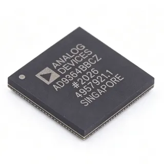
AD9364BBCZ-REEL - 70MHz-6GHz RF Agile Transceiver | Analog Devices
部品番号: AD9364BBCZ-REEL ✓ 生産中| 数量 | 単価 | 小計 |
|---|---|---|
| 1 | $89.5 | $89.50 |
| 10 | $82.3 | $823.00 |
| 100 | $74.1 | $7,410.00 |
| 500 | $66.8 | $33,400.00 |
| 1,000 | $59.9 | $59,900.00 |
AD9364BBCZ-REEL 概要
An RF transceiver is a device that combines both a transmitter and a receiver in a single package, handling the modulation, demodulation, and frequency conversion of RF signals. It is a critical component in wireless communication systems, bridging the analog RF domain and the digital baseband processor. The AD9364 belongs to the RF Agile Transceiver family, which includes the AD9361 (2x2) and AD9363 (1x1, reduced bandwidth), all sharing a similar architecture and programming model.
Key features of the AD9364 include a wide frequency range of 70 MHz to 6 GHz, support for channel bandwidths from 200 kHz to 56 MHz, and a configurable digital interface (CMOS/LVDS) for baseband connectivity. The device offers excellent receiver sensitivity and transmitter linearity, with an output power of 8 dBm. It also includes integrated fractional-N synthesizers, reducing external component count and simplifying frequency planning.
Technically, the AD9364 employs a direct-conversion architecture with advanced calibration algorithms to minimize I/Q imbalance and DC offset. The device supports both FDD and TDD modes, making it versatile for various wireless standards. Its programmability allows dynamic reconfiguration of frequency, bandwidth, and gain, enabling software-defined radio (SDR) implementations.
Typical applications include 3G/4G base stations, software-defined radios, portable test equipment, and military communications. The wide frequency range and bandwidth flexibility make it suitable for multi-standard radios that must operate across different bands.
When designing with the AD9364, careful attention must be paid to power supply decoupling and clocking. The device requires multiple supply rails, and proper filtering is essential to achieve optimal performance. The digital interface should be configured for the appropriate voltage levels and data rate to match the baseband processor.
ドロップイン代替品: AD9364BBCZ-REEL — 同一パッケージでピン互換。PCBの作り直しが必要な異なるパッケージの部品は除外されています。
このシリーズのバリエーション
同一シリーズでドロップイン互換のモデル: AD9364BBCZ-REEL (同一形状・フットプリント) — 相違点: Channel Bandwidth, Frequency Range, Interface, Number of Channels.
クイック比較ツール — 並列比較する代替部品を選択:
AD9364BBCZ
✅ ドロップイン✓ 在庫あり
$59.7 / 個
データシートを見る →AD9361BBCZ
⚡ 同一パッケージ✓ 在庫あり
$62 / 個
データシートを見る →AD9363ABCZ
⚡ 同一パッケージ ⚠️ 仕様未検証📋 参考代替品(カタログ未掲載)
AD9364BBCZ-REEL 仕様
| Type | RF Transceiver |
| Frequency Range | 70 MHz ~ 6 GHz |
| Number of Channels | 1x1 (1 RX, 1 TX) |
| Channel Bandwidth | 200 kHz ~ 56 MHz |
| Output Power | 8 dBm |
| インターフェース | CMOS/LVDS |
| パッケージ | 144-LFBGA, CSPBGA |
| 実装タイプ | Surface Mount |
| ピン数 | 144 |
| RF Type | Cellular LTE |
| RoHS ステータス | Compliant |
| REACH Status | Compliant |
AD9364BBCZ-REEL ピン構成
| ピン A1 | VSSA — Analog ground |
| ピン A2 | VSSA — Analog ground |
| ピン B1 | RX1P — Receiver 1 positive input |
| ピン B2 | RX1N — Receiver 1 negative input |
| ピン C1 | TX1P — Transmitter 1 positive output |
| ピン C2 | TX1N — Transmitter 1 negative output |
| ピン D1 | VDD — Power supply |
| ピン D2 | VDD — Power supply |
| ピン E1 | CLKIN — Reference clock input |
| ピン E2 | CLKOUT — Clock output |
| ピン F1 | SPI_CS — SPI chip select |
| ピン F2 | SPI_CLK — SPI clock |
| ピン G1 | SPI_SDIO — SPI data |
| ピン G2 | SPI_SDO — SPI data out |
| ピン H1 | ENABLE — Enable pin |
| ピン H2 | RESET — Reset pin |
主な用途
AD9364BBCZ-REEL の用途: 6 件s: 3G/4G Base Stations, Software-Defined Radio (SDR), Portable Test Equipment, Military Communications, IoT Gateways, Point-to-Point Microwave Links.
3G/4G Base Stations
The AD9364BBCZ-REEL is ideal for 3G and 4G base stations due to its wide frequency range (70 MHz to 6 GHz) and support for channel bandwidths up to 56 MHz. It provides a single-channel RF front end that can be configured for FDD or TDD operation, enabling flexible radio designs. The integrated synthesizers reduce external component count, simplifying the BOM and PCB layout. Its high linearity and sensitivity ensure reliable communication in demanding cellular environments.
おすすめ
Software-Defined Radio (SDR)
The AD9364BBCZ-REEL is a cornerstone for SDR platforms, offering programmable frequency, bandwidth, and gain. Its configurable digital interface (CMOS/LVDS) connects directly to FPGAs or processors, enabling reconfigurable radios that can adapt to multiple standards. The wide frequency coverage from 70 MHz to 6 GHz allows a single hardware platform to operate across HF, VHF, UHF, and microwave bands. This flexibility makes it ideal for military, amateur, and commercial SDR applications.
おすすめ
Portable Test Equipment
The AD9364BBCZ-REEL is well-suited for portable spectrum analyzers, signal generators, and RF testers due to its compact 144-ball LFBGA package and low power consumption. Its wide frequency range and programmable bandwidth allow a single device to cover multiple test scenarios. The integrated synthesizers and calibration features reduce external components, making it easier to design compact, battery-powered instruments. The device's high dynamic range ensures accurate measurements in various environments.
おすすめ
Military Communications
The AD9364BBCZ-REEL is designed for military communication systems requiring secure, wideband, and frequency-agile radios. Its 70 MHz to 6 GHz range covers many military bands, and its programmable bandwidth supports various waveforms. The device's high linearity and sensitivity are critical for reliable communication in contested environments. The configurable interface allows integration with encryption and waveform processing modules, making it a versatile choice for defense applications.
おすすめ
IoT Gateways
The AD9364BBCZ-REEL can be used in IoT gateways that need to support multiple wireless standards (e.g., LoRa, NB-IoT, Wi-Fi) in a single device. Its wide frequency range and programmable bandwidth allow the gateway to adapt to different protocols. The device's low power consumption is beneficial for always-on gateways, and its small package saves board space. The configurable digital interface simplifies connection to host processors, enabling flexible protocol handling.
おすすめ
Point-to-Point Microwave Links
The AD9364BBCZ-REEL is suitable for point-to-point microwave links operating in licensed bands up to 6 GHz. Its high output power (8 dBm) and excellent receiver sensitivity enable reliable long-distance communication. The device supports channel bandwidths up to 56 MHz, allowing high-capacity links. The integrated synthesizers provide precise frequency control, essential for maintaining link stability. The compact package and low power consumption make it ideal for outdoor units.
おすすめ
おすすめ製品の概要
エンジニアリング参考データ: AD9364BBCZ-REEL — 比較、設計ガイダンス、コンプライアンス情報。
選定ガイド
代替品との比較
| パラメータ | この製品 | AD9364BBCZ | AD9361BBCZ | AD9363ABCZ |
|---|---|---|---|---|
| Package | 144-LFBGA, CSPBGA | 144-LFBGA, CSPBGA | 144-LFBGA, CSPBGA | 144-LFBGA, CSPBGA |
| Brand | Analog Devices | Analog Devices | Analog Devices | Analog Devices |
| Number of Channels | 1x1 | 1x1 | 2x2 | 1x1 |
| Frequency Range | 70 MHz ~ 6 GHz | 70 MHz ~ 6 GHz | 70 MHz ~ 6 GHz | 325 MHz ~ 3.8 GHz |
| Channel Bandwidth | 200 kHz ~ 56 MHz | 200 kHz ~ 56 MHz | 200 kHz ~ 56 MHz | 200 kHz ~ 20 MHz |
| Output Power | 8 dBm | 8 dBm | 8 dBm | 8 dBm |
| Pin Compatibility | Reference | Yes | No (some pins VSSA) | No |
| Packaging | Tape & Reel | Tray | Tray | Tray |
主な差別化要因
- Wide frequency range (70 MHz to 6 GHz) (vs AD9363ABCZ)
- Higher channel bandwidth (up to 56 MHz) (vs AD9363ABCZ)
- Pin compatibility with AD9364BBCZ (vs AD9361BBCZ)
設計ノート
The AD9364 requires multiple supply rails (e.g., 1.3V, 2.5V, 3.3V). Use low-noise LDOs for analog supplies and switching regulators for digital supplies. Ensure proper decoupling with 100nF capacitors close to each supply pin and a 10uF bulk capacitor per rail. Refer to the AD9364 reference design for recommended power supply architecture.
For optimal RF performance, use a 4-layer PCB with a solid ground plane. Place the AD9364 on the top layer with controlled impedance traces for RF inputs/outputs (50 ohms). Keep digital signals away from RF traces to minimize coupling. Follow the layout guidelines in the AD9364 datasheet for the LFBGA package, including via placement for thermal and ground connections.
Ensure the reference clock is clean and stable; use a low-jitter oscillator. The SPI interface must be configured correctly for the desired mode (single or dual). Unused receiver pins should be terminated properly (e.g., connected to ground through a capacitor) to avoid noise. Also, verify the power-up sequence as specified in the datasheet to prevent latch-up.
コンプライアンス情報
RoHS compliant per Analog Devices product page. REACH compliance is assumed based on ADI's policy. AEC-Q100 not applicable for this RF transceiver.