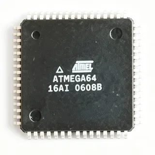
ATMEGA164PA-AN - 8-Bit AVR MCU 16KB Flash 20MHz | Microchip
部品番号: ATMEGA164PA-AN ✓ 生産中| 数量 | 単価 | 小計 |
|---|---|---|
| 1 | $2.35 | $2.35 |
| 10 | $2.1 | $21.00 |
| 100 | $1.86 | $186.00 |
| 500 | $1.68 | $840.00 |
| 1,000 | $1.52 | $1,520.00 |
ATMEGA164PA-AN 概要
A microcontroller unit (MCU) is a single integrated circuit that combines a processor core, program memory, data memory, and peripherals into one chip, sitting at the device level of the embedded-systems hierarchy (semiconductor -> integrated circuit -> microcontroller -> embedded system). The AVR family uses a modified Harvard RISC architecture in which most instructions execute in a single clock cycle, and the picoPower technology subfamily adds aggressive sleep-mode and clock-gating features for ultra-low average power consumption.
Key features of the ATMEGA164PA-AN include 16 KB of self-programmable ISP flash with read-while-write support, 512 B of EEPROM for non-volatile parameter storage, two USARTs for dual serial channels, a byte-oriented Two-Wire (I2C-compatible) interface, and an SPI interface. Peripherals include three flexible timer/counters with compare modes and PWM outputs, brown-out detection, power-on reset, a watchdog timer, and an 8-channel 10-bit ADC.
The AVR core provides 32 general-purpose working registers directly connected to the ALU, enabling single-cycle execution and high code efficiency. The picoPower process technology delivers low active current plus multiple sleep modes (Idle, ADC Noise Reduction, Power-save, Power-down, Standby, and Extended Standby), allowing battery-powered designs to reach microamp-level sleep currents. The 8-channel 10-bit ADC supports single-ended and differential conversions with gain stages, suitable for direct sensor interfacing.
Typical applications include battery-powered instrumentation, industrial control and sensor nodes, consumer appliances, and motor or LED control systems that leverage the PWM channels and dual USART connectivity. The wide 2.5 V to 5.5 V supply range supports both 3.3 V and 5 V designs.
When designing with this device, reserve PB6/PB7 for crystal operation or use the internal RC oscillator to free two I/O pins, and always enable brown-out detection when running from batteries to prevent EEPROM corruption during power collapse.
This page synthesizes verified distributor data, drop-in ATmega-family alternatives, and practical design notes not found in the manufacturer datasheet.
ドロップイン代替品: ATMEGA164PA-AN — 同一パッケージでピン互換。PCBの作り直しが必要な異なるパッケージの部品は除外されています。
このシリーズのバリエーション
同一シリーズでドロップイン互換のモデル: ATMEGA164PA-AN (同一形状・フットプリント) — 相違点: Package, EEPROM, SRAM, ADC, Core Architecture.
クイック比較ツール — 並列比較する代替部品を選択:
ATMEGA164PA-AU
✅ ドロップイン✓ 在庫あり
$2.75 / 個
データシートを見る →ATMEGA164P-20AU
✅ ドロップイン📋 参考代替品(カタログ未掲載)
ATMEGA324PA-AU
✅ ドロップイン ⚠️ 仕様未検証✓ 在庫あり
$2.87 / 個
データシートを見る →ATMEGA644PA-AU
✅ ドロップイン ⚠️ 仕様未検証✓ 在庫あり
$4.61 / 個
データシートを見る →ATMEGA1284P-AU
✅ ドロップイン ⚠️ 仕様未検証✓ 在庫あり
$4.65 / 個
データシートを見る →ATMEGA164PA-AN 最大定格&電気的特性
| Core Processor | AVR |
| Core Size | 8-Bit |
| Maximum Clock Speed | 20 MHz |
| Program Memory Size | 16 KB (8K x 16) Flash |
| Program Memory Type | ISP FLASH (read-while-write) |
| EEPROM Size | 512 B |
| RAM Size | 1 KB SRAM |
| Number of I/O | 32 |
| Supply Voltage Range | 2.5 V to 5.5 V |
| Connectivity | I2C (Two-Wire), SPI, UART/USART (x2) |
| Peripherals | Brown-out Detect/Reset, POR, PWM, WDT |
| ADC Resolution | 10-bit, 8-channel |
| パッケージ | 44-TQFP (10 x 10 mm) |
| 実装タイプ | Surface Mount |
| Series | AVR ATmega picoPower |
| Part Status | Active |
ATMEGA164PA-AN 44-tqfp (10 x 10 mm) ピン配置ガイド
ATMEGA164PA-AN (44-tqfp (10 x 10 mm) パッケージ) のピン配置。 このデジタルICには、GPIO、通信インターフェース (UART、SPI、I2C)、および電源ピンが含まれています。代替ピン機能と設定オプションについては、メーカーのデータシートを参照してください。組み込みシステム設計とPCBレイアウトに不可欠です。

詳細なピン配置データはありません: ATMEGA164PA-AN.
詳細は データシート をご参照ください。
主な用途
ATMEGA164PA-AN の用途: 6 件s: Battery-Powered Sensor Nodes, Industrial Control and Automation, Embedded Serial Communication Bridges, Motor and LED Control, Portable Measurement Instruments, Hobby, Maker, and Educational Platforms.
Battery-Powered Sensor Nodes
The ATMEGA164PA-AN fits battery-powered sensing products because its picoPower technology minimizes energy in sleep while retaining RAM and wake sources. A typical node sleeps in Power-down mode and wakes on pin-change interrupt or watchdog timeout, samples a sensor through the 8-channel 10-bit ADC, and transmits over one of the two USARTs. Running at 3.3 V and a reduced clock keeps active current low, while the 2.5 V floor permits direct operation from two alkaline cells. The 512 B EEPROM stores calibration and cumulative counters without wear-sensitive flash writes, extending field life and eliminating battery-pull EEPROM components from the BOM.
おすすめ
Industrial Control and Automation
In industrial controllers the ATMEGA164PA-AN provides deterministic 8-bit control with single-cycle AVR instruction execution at up to 20 MHz, so interrupt latency and loop timing are predictable. Brown-out detection and the watchdog timer deliver the reset integrity required around 24 V backplane environments, while the 2.5 V to 5.5 V supply range eases integration with legacy 5 V PLC I/O. Dual USARTs allow simultaneous RS-485 Modbus fieldbus communication and a local HMI link, and three timers generate PWM for actuator or heater control. The 44-pin TQFP gives 32 GPIO, enough to drive relays, read limit switches, and bit-bang auxiliary protocols without port expanders.
おすすめ
Embedded Serial Communication Bridges
With two independent USARTs plus hardware SPI and a byte-oriented Two-Wire (I2C) interface, the ATMEGA164PA-AN is well suited to protocol-conversion duties such as RS-232-to-RS-485 gateways, UART-to-SPI adapters, and Modbus RTU routers. The dual serial channels allow full-duplex bridging without software serial emulation, preserving timing accuracy at 115200 baud and beyond at 20 MHz. The 16 KB flash holds protocol stacks and buffering logic within the 1 KB SRAM envelope, and read-while-write flash permits field firmware updates over the serial link using self-programming, reducing maintenance cost in installed hardware.
おすすめ
Motor and LED Control
The ATMEGA164PA-AN's three flexible timer/counters with compare modes generate multiple PWM channels for DC motor speed control, servo positioning, and dimmable LED drivers. Timer outputs are hardware-generated, so PWM frequency and duty stay glitch-free even while the CPU handles ADC sampling or serial traffic. The 10-bit ADC can read current-sense shunts or potentiometer feedback for closed-loop control, and differential ADC modes with gain allow direct low-side shunt measurement. Operating at 5 V gives strong GPIO drive for MOSFET gate interfaces in small motor drivers used in appliances, toys, and HVAC dampers.
おすすめ
Portable Measurement Instruments
Handheld meters and dataloggers benefit from the ATMEGA164PA-AN's combination of a 10-bit ADC with an ADC Noise Reduction sleep mode, which suppresses digital switching during conversions to improve measurement repeatability. Differential inputs with selectable gain permit direct connection of bridge sensors such as strain gauges and RTDs. The 512 B EEPROM retains calibration constants and logged minima between battery changes, while picoPower sleep modes extend operation on coin or AAA cells. The 32 GPIO lines easily drive segment LCDs or OLED displays plus a keypad matrix, and the 44-TQFP 10 x 10 mm footprint fits compact handheld enclosures.
おすすめ
Hobby, Maker, and Educational Platforms
The ATMEGA164PA-AN is popular in custom maker boards because it programs with ISP tools and open-source toolchains such as avr-gcc and MightyCore, which bring ATmega164/324/644/1284 support to Arduino-style development. Compared to the ATmega328P, the extra dual USART and larger port count let beginners drive more LEDs, servos, and sensors without shift registers, while remaining code-compatible with classic AVR tutorials. Through-hole prototyping paths exist via the same die in DIP packaging variants, and the wide 2.5 V to 5.5 V supply range tolerates bench-supply experimentation and USB-powered setups alike.
おすすめ
おすすめ製品の概要
エンジニアリング参考データ: ATMEGA164PA-AN — 比較、設計ガイダンス、コンプライアンス情報。
選定ガイド
代替品との比較
| パラメータ | この製品 | ATMEGA164PA-AU | ATMEGA164P-20AU | ATMEGA324PA-AU | ATMEGA644PA-AU | ATMEGA1284P-AU |
|---|---|---|---|---|---|---|
| Package | TQFP-44 (10 x 10 mm) | TQFP-44 - same footprint | TQFP-44 - same footprint | TQFP-44 - same footprint | TQFP-44 - same footprint | TQFP-44 - same footprint |
| Brand | Microchip Technology | Microchip Technology | Microchip Technology | Microchip Technology | Microchip Technology | Microchip Technology |
| Flash Memory | 16 KB | 16 KB | 16 KB | 32 KB | 64 KB | 128 KB |
| SRAM | 1 KB | 1 KB | 1 KB | 2 KB | 4 KB | 16 KB |
| EEPROM | 512 B | 512 B | 512 B | 1 KB | 2 KB | 4 KB |
| Max Clock Speed | 20 MHz | 20 MHz | 20 MHz | 20 MHz | 20 MHz | 20 MHz |
| GPIO | 32 | 32 | 32 | 32 | 32 | 32 |
| Process Generation / Low-Power Grade | picoPower (PA) | picoPower (PA) | picoPower (P, prior process) | picoPower (PA) | picoPower (PA) | picoPower (P) |
| Relative Unit Cost | Baseline (lowest in family) | Baseline | Baseline | Slightly higher | Moderately higher | Substantially higher |
主な差別化要因
- Lowest-cost entry point of the 44-pin picoPower ATmega family (vs ATMEGA324PA-AU)
- Dual USART in the 16 KB class (vs ATMEGA164PA-AU)
- Upgrade path without PCB rework (vs ATMEGA1284P-AU)
設計ノート
Decouple VCC and AVCC independently with 100 nF ceramic capacitors placed within a few millimeters of pins 1, 19, and 41, plus a 10 uF bulk capacitor near the regulator. Connect AVCC to VCC through a low-pass LC filter (10 uH inductor plus 100 nF) when ADC accuracy matters, and keep analog signals away from switching traces. Always enable brown-out detection (set BODLEVEL fuse appropriate to your supply rail) when running from batteries, so EEPROM writes cannot corrupt during power collapse. Estimated: a node sleeping most of the time in Power-down and waking for 10 ms every second keeps average current dominated by sleep current per the Microchip picoPower specifications.
The 44-TQFP 10 x 10 mm package has 0.8 mm pin pitch, which is hand-solderable with drag soldering but demands correct land pattern per the Microchip package drawing. Route the crystal (PB6/PB7) with short traces and guard it with a ground ring; keep the XTAL area clear of high-current PWM returns. Use pin-change interrupts on any of the 32 GPIO for wake sources in low-power designs, and reserve Port A for analog functions when possible since all eight ADC channels share it. If migrating between ATmega164/324/644/1284 footprints later, keeping the 44-TQFP land pattern identical enables drop-in flash upgrades with zero PCB rework.
Maximum clock frequency derates with supply voltage: 20 MHz requires operation near 5 V, so verify the frequency-versus-voltage curve in the manufacturer datasheet before clocking a 3.3 V design above roughly 13-14 MHz (estimated from the standard ATmega voltage-frequency derating curves - confirm against the datasheet chart for your temperature range). Do not exceed the absolute maximum ratings on any pin relative to GND. When substituting the ATmega164P for the PA, note per application note AVR527 that although the parts are functionally identical drop-ins, some electrical characteristics differ due to the process change - re-verify sleep currents and BOD thresholds.
コンプライアンス情報
Mouser listing describes the ATMEGA164PA-AN as 'Grn' (green/lead-free packaging designation per Microchip nomenclature), but explicit RoHS/REACH certificate values were not present in the provided verified data; consult Microchip's product page for current compliance certificates.