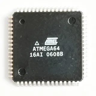
ATMEGA8515L-8AC - 8KB Flash 8MHz AVR MCU | Microchip
部品番号: ATMEGA8515L-8AC ✓ 生産中| 数量 | 単価 | 小計 |
|---|---|---|
| 1 | $5.4 | $5.40 |
| 10 | $4.86 | $48.60 |
| 100 | $4.32 | $432.00 |
| 500 | $3.9 | $1,950.00 |
| 1,000 | $3.5 | $3,500.00 |
ATMEGA8515L-8AC 概要
An 8-bit microcontroller is a single-chip computer that integrates a CPU core, program memory, data memory, and peripherals on one silicon die. The AVR family uses a Harvard-architecture RISC core in which most of its 130 instructions execute in a single clock cycle, placing this device in the embedded microcontroller class of the broader semiconductor hierarchy (MCU -> 8-bit MCU -> AVR ATmega family).
Key features include up to 8 MIPS throughput at 8 MHz, fully static operation, in-system programmable Flash for field firmware updates, and a wide supply-voltage range for the L (low-voltage) speed grade, allowing operation down to about 2.7 V while remaining 5 V tolerant for legacy industrial designs. Peripheral set includes an 8-bit timer with PWM, a 16-bit timer, USART serial port, SPI, and an external memory interface for up to 64 KB of SRAM.
The AVR enhanced RISC architecture pairs 32 general-purpose working registers directly with the ALU, so one instruction can load a register and perform an operation in a single cycle. This produces efficient C-compiled code density and deterministic execution, a core reason the ATmega family remains popular in legacy industrial systems.
Typical applications include industrial control panels, embedded legacy equipment maintenance, motor and actuator control, and educational/hobby development boards where the external memory bus and expanded I/O of the ATmega8515 are required.
A key design consideration is clock selection: the L-8AC grade is specified to 8 MHz, so systems designed for the 16 MHz ATMEGA8515-16A* grades must either derate the oscillator or select the faster part.
This page synthesizes distributor inventory, drop-in alternatives, and practical design notes not found in the manufacturer datasheet.
ドロップイン代替品: ATMEGA8515L-8AC — 同一パッケージでピン互換。PCBの作り直しが必要な異なるパッケージの部品は除外されています。
このシリーズのバリエーション
同一シリーズでドロップイン互換のモデル: ATMEGA8515L-8AC (同一形状・フットプリント) — 相違点: Package, Throughput, Operating Temperature, Packaging, Mounting Type.
クイック比較ツール — 並列比較する代替部品を選択:
ATMEGA8515-16AUR
✅ ドロップイン✓ 在庫あり
$2.35 / 個
データシートを見る →ATMEGA8515-16AI
✅ ドロップイン ⚠️ 仕様未検証✓ 在庫あり
$4.1 / 個
データシートを見る →ATMEGA8515L-8AUR
✅ ドロップイン ⚠️ 仕様未検証✓ 在庫あり
$1.98 / 個
データシートを見る →ATMEGA8515-16AUR
✅ ドロップイン ⚠️ 仕様未検証✓ 在庫あり
$2.35 / 個
データシートを見る →ATMEGA8515L-8AU
✅ ドロップイン ⚠️ 仕様未検証📋 参考代替品(カタログ未掲載)
ATMEGA8515L-8AC 最大定格&電気的特性
| Core Architecture | 8-bit AVR RISC |
| Flash Program Memory | 8 KB (4K x 16), In-System Programmable |
| EEPROM Data Memory | 512 B |
| Internal SRAM | 544 B |
| External SRAM Support | Up to 64 KB |
| 最大クロック周波数 | 8 MHz |
| Throughput | Up to 8 MIPS at 8 MHz (16 MIPS at 16 MHz for faster grades) |
| Instruction Set | 130 powerful instructions, mostly single-cycle |
| General Purpose Working Registers | 8 x 8-bit (32-register file per AVR architecture) |
| パッケージ | 44-TQFP (10 x 10 mm) |
| 実装タイプ | Surface Mount |
| Peripheral Set | USART, SPI, 8-bit timer with PWM, 16-bit timer, external memory interface |
| Programming Interface | In-System Programming (ISP) / ICSP via MPLAB SNAP |
ATMEGA8515L-8AC 44-tqfp (10 x 10 mm) ピン配置ガイド
ATMEGA8515L-8AC (44-tqfp (10 x 10 mm) パッケージ) のピン配置。 このデジタルICには、GPIO、通信インターフェース (UART、SPI、I2C)、および電源ピンが含まれています。代替ピン機能と設定オプションについては、メーカーのデータシートを参照してください。組み込みシステム設計とPCBレイアウトに不可欠です。

詳細なピン配置データはありません: ATMEGA8515L-8AC.
詳細は データシート をご参照ください。
主な用途
ATMEGA8515L-8AC の用途: 6 件s: Industrial Control Panels, Legacy Equipment Maintenance and Repair, External-Memory Embedded Systems, Motor and Actuator Control, Educational and Development Boards, Instrumentation Front Ends.
Industrial Control Panels
The ATMEGA8515L-8AC fits industrial control panels because its 8 KB ISP Flash holds typical sequencer firmware, its 544 B internal SRAM extends to 64 KB external SRAM for logging buffers, and its 44-pin TQFP exposes 35+ GPIO organized on Ports A-D plus Port E for relay, keypad, and indicator interfacing. The USART handles Modbus-style RS-485 links via an external transceiver, while the SPI port drives displays or ADCs. Using the L-grade at 8 MHz reduces radiated emissions and allows low-voltage operation in noise-sensitive cabinets; the external memory bus is the decisive advantage when recipes or event logs exceed internal RAM.
おすすめ
Legacy Equipment Maintenance and Repair
Many deployed ATmega8515-based boards need replacements decades after original design, and the ATMEGA8515L-8AC serves exactly this maintenance market: identical electrical behavior preserves firmware compatibility with code compiled under legacy AVR-GCC or IAR toolchains, and in-system programming via MPLAB SNAP (two I/O pins plus reset per Microchip) allows field reflashing without desoldering. Because the part shares its 44-TQFP footprint with ATMEGA8515-16AU grades, repair shops can stock one footprint and choose 8 MHz or 16 MHz grades per board revision, minimizing BOM proliferation in spares inventory.
おすすめ
External-Memory Embedded Systems
The defining feature of the ATmega8515 family is its external memory interface: Port A forms a multiplexed 8-bit address/data bus and Port C supplies the high address byte, addressing up to 64 KB of external SRAM. The ATMEGA8515L-8AC exploits this for applications such as data loggers and protocol analyzers where 544 B of internal SRAM is insufficient. The 8 MHz L-grade provides ample bandwidth (up to 8 MIPS) while keeping external SRAM timing relaxed, so low-cost standard SRAM ICs interface without wait states in most configurations - a practical advantage over faster grades that demand tighter memory access timing.
おすすめ
Motor and Actuator Control
The ATMEGA8515L-8AC generates multi-channel PWM through its 8-bit timer OC0 output (PD7) and 16-bit Timer1 compare outputs OC1A/OC1B (PD5/PD4), supporting DC motor speed control, servo actuation, and stepper sequencing at 8 MHz. Its 544 B SRAM handles position tables, and the external memory interface buffers motion profiles when needed. At 8 MHz the PWM resolution and interrupt latency suit low-to-mid performance drives; input capture (ICP1 on PD6) provides precise encoder or hall-sensor timing measurement. For brushless FOC drives, pair with gate drivers rather than expecting the MCU alone to close fast current loops.
おすすめ
Educational and Development Boards
The ATMEGA8515L-8AC remains popular in university embedded-systems labs because the ATmega8515's expanded bus architecture demonstrates memory interfacing concepts (multiplexed address/data latching, wait states) that smaller AVRs cannot show, while the 130-instruction AVR RISC core teaches single-cycle execution principles. The 8 MHz L-grade tolerates student power mistakes across a wide voltage range, and ISP programming via MPLAB SNAP or legacy AVRISP keeps lab infrastructure inexpensive. Breadboard-friendly 44-TQFP adapter boards and mature AVR-GCC/AVR Studio toolchains make firmware development straightforward for newcomers to 8-bit microcontroller programming.
おすすめ
Instrumentation Front Ends
In measurement and instrumentation front ends, the ATMEGA8515L-8AC provides USART and SPI connectivity for external precision ADCs and user interfaces, while its deterministic single-cycle RISC execution gives consistent interrupt service timing for sampling routines. The input capture pin (PD6) timestamps external events with timer resolution, useful for frequency and period measurement up to the 8 MHz clock limit. With 8 KB Flash there is room for linearization tables and command parsing, and the 64 KB external memory option supports waveform capture buffers - a combination legacy test fixtures and bench instruments continue to rely on today.
おすすめ
おすすめ製品の概要
エンジニアリング参考データ: ATMEGA8515L-8AC — 比較、設計ガイダンス、コンプライアンス情報。
選定ガイド
代替品との比較
| パラメータ | この製品 | ATMEGA8515-16AUR | ATMEGA8515-16AI | ATMEGA8515L-8AUR |
|---|---|---|---|---|
| Package | 44-TQFP (10 x 10 mm) | 44-TQFP (10 x 10 mm) - same | 44-TQFP (10 x 10 mm) - same | 44-TQFP (10 x 10 mm) - same |
| Brand | Microchip Technology (Atmel) | Microchip Technology | Microchip Technology | Microchip Technology |
| Max Clock Frequency | 8 MHz | 16 MHz | 16 MHz | 8 MHz |
| Flash Memory | 8 KB (4K x 16) ISP | 8 KB (4K x 16) ISP | 8 KB (4K x 16) ISP | 8 KB (4K x 16) ISP |
| EEPROM | 512 B | 512 B | 512 B | 512 B |
| External SRAM Support | Up to 64 KB | Up to 64 KB | Up to 64 KB | Up to 64 KB |
| Throughput | 8 MIPS at 8 MHz | 16 MIPS at 16 MHz | 16 MIPS at 16 MHz | 8 MIPS at 8 MHz |
| Temperature / Packaging Grade | Commercial (AC suffix) | Industrial, GREEN T&R | Industrial TQFP | Industrial, GREEN T&R |
主な差別化要因
- Low-voltage 8 MHz speed grade for relaxed timing and low EMI (vs ATMEGA8515-16AUR)
- External memory interface to 64 KB SRAM (vs ATMEGA48PA-AUR)
- Commercial temperature AC variant vs industrial AUR (vs ATMEGA8515L-8AUR)
設計ノート
As an L speed grade, the ATMEGA8515L-8AC is the low-voltage variant of the ATmega8515 family, but the exact supply rails are not stated in the retrieved web data - confirm the minimum and maximum VCC in the manufacturer datasheet before finalizing the power budget (Mouser describes it as a 3V-class part). At 8 MHz active current is modest (single-digit mA per family norms), so a simple LDO or 5 V rail with adequate decoupling suffices. Estimated: at ~10 mA active current from a 5 V rail, dissipation is only 50 mW - no heatsinking concerns.
Place 100 nF ceramic decoupling capacitors at each VCC pin pair of the 44-TQFP, close to the pins, plus a 10 uF bulk capacitor near the supply entry. Keep the XTAL1/XTAL2 crystal traces short and guard them with ground. If the external memory bus is used, route the multiplexed Port A address/data lines with matched lengths to a 74xx573 latch and keep stubs short to avoid signal integrity issues at 8 MHz; use a 1% tolerance reset RC or a dedicated supervisor for reliable power-on reset.
The most common design mistake is substituting an 8 MHz L-grade where 16 MHz timing was assumed: the ATMEGA8515L-8AC is limited to 8 MHz, so verify fuse settings (clock source/CKOPT) match your crystal, and recompile firmware with F_CPU=8000000 if migrating from 16 MHz boards. UART baud rates and delay libraries scale with F_CPU and will be wrong otherwise. Also confirm SPI ISP programming pins are not loaded by peripherals during reset, which is the top cause of field reprogramming failures.
コンプライアンス情報
Compliance status was not stated in the retrieved web data; related family parts use GREEN (RoHS) packaging per FindIC replace-part descriptions, but confirm on the Microchip product page for this exact MPN.