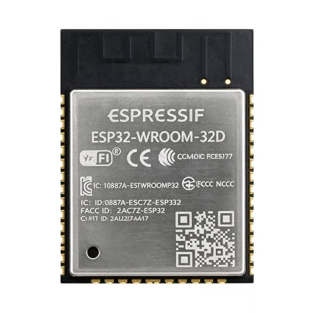
ESP32-WROOM-32E-N8R2 - WiFi/BT 4.2 Module, 8MB Flash | Espressif
部品番号: ESP32-WROOM-32E-N8R2 ✓ 生産中| 数量 | 単価 | 小計 |
|---|---|---|
| 1 | $5.0625 | $5.06 |
| 10 | $3.6563 | $36.56 |
| 100 | $3.2344 | $323.44 |
| 500 | $3.0938 | $1,546.90 |
| 1,000 | $2.9531 | $2,953.10 |
ESP32-WROOM-32E-N8R2 概要
A Wi-Fi MCU module is a self-contained wireless system that integrates a microcontroller, radio transceiver, antenna, RF matching network, flash memory and power management on one certified PCB. Within the product hierarchy it sits between a bare SoC and a full development board: it offers complete radio certification and shielding without the overhead of a carrier board, making it the standard building block for power management, connectivity and edge computing in IoT endpoints.
Key features of the N8R2 variant include 802.11 b/g/n Wi-Fi with 150 Mbps PHY rate, Bluetooth v4.2 BR/EDR and BLE, dual-core LX6 operation for concurrent application and protocol processing, and 26 GPIOs with a rich peripheral set (SPI, I2S, I2C, UART, ADC, DAC, PWM, touch). The 8 MB flash plus 2 MB PSRAM configuration gives headroom for OTA update partitions, larger TLS stacks and display frame buffers that smaller N4/N8 variants cannot support.
Technically, the module integrates antenna switches, RF balun, power amplifier, low-noise receive amplifier, filters and power management on the embedded ESP32-D0WD-V3 silicon, achieving higher stability and safety performance than the original ESP32-WROOM-32. The V3 die revision adds security features such as flash encryption and secure boot support.
Typical applications include smart-home devices, industrial controllers and wireless sensor nodes where both Wi-Fi and Bluetooth connectivity and extra RAM are required in a single certified footprint.
Design-wise, supply the module from a clean 3.3 V rail capable of delivering 500 mA peaks, and keep the antenna region free of copper and enclosures with high dielectric constants.
This page synthesizes distributor pricing, memory-variant drop-in options and practical design notes not found in the manufacturer datasheet. Pricing references are as of 2026-09-15.
ドロップイン代替品: ESP32-WROOM-32E-N8R2 — 同一パッケージでピン互換。PCBの作り直しが必要な異なるパッケージの部品は除外されています。
クイック比較ツール — 並列比較する代替部品を選択:
ESP32-WROOM-32E-N8
✓ 在庫あり
$3.7734 / 個
データシートを見る →ESP32-WROOM-32E-N8R8
📋 参考代替品(カタログ未掲載)
ESP32-WROOM-32E-N4
📋 参考代替品(カタログ未掲載)
ESP32-WROOM-32E-N16
📋 参考代替品(カタログ未掲載)
ESP32-WROOM-32UE-N8
📋 参考代替品(カタログ未掲載)
ESP32-WROOM-32E-N8R2 仕様(メーカー公開)
| RF Frequency | 2.4 GHz |
| Wi-Fi Standard | 802.11 b/g/n |
| Bluetooth | v4.2 BR/EDR and BLE, Class 1, 2 and 3 |
| MCU Core | Xtensa dual-core 32-bit LX6 (ESP32-D0WD-V3 / ESP32-D0WDR2-V3) |
| Flash Memory | 8 MB |
| PSRAM | 2 MB |
| 電源電圧 | 3 V to 3.6 V |
| GPIO Count | 26 |
| Antenna | Onboard PCB trace antenna |
| 実装タイプ | Surface Mount |
| Embedded Security | Flash encryption and secure boot support (V3 silicon) |
| Peripherals | SPI, I2C, I2S, UART, ADC, DAC, PWM, touch sensor |
| RoHS ステータス | Compliant |
ESP32-WROOM-32E-N8R2 ピン構成
| ピン 1 | GND — Ground |
| ピン 2 | 3V3 — Power supply (3.0 V to 3.6 V) |
| ピン 3 | EN — RF enable, active high (chip enable) |
| ピン 4 | SENSOR_VP — ADC pre-amplifier positive input (GPIO36) |
| ピン 5 | SENSOR_VN — ADC pre-amplifier negative input (GPIO39) |
| ピン 6 | IO34 — GPIO34, input only, ADC1_CH6 |
| ピン 7 | IO35 — GPIO35, input only, ADC1_CH7 |
| ピン 8 | IO32 — GPIO32, ADC1_CH4, touch sensor 9 |
| ピン 9 | IO33 — GPIO33, ADC1_CH5, touch sensor 8 |
| ピン 10 | IO25 — GPIO25, DAC1, ADC2_CH8 |
| ピン 11 | IO26 — GPIO26, DAC2, ADC2_CH9 |
| ピン 12 | IO27 — GPIO27, ADC2_CH7, touch sensor 7 |
| ピン 13 | IO14 — GPIO14, ADC2_CH6, touch sensor 6, HS2_CLK |
| ピン 14 | IO12 — GPIO12, MTDI strapping pin (flash voltage), ADC2_CH5 |
| ピン 15 | GND — Ground |
| ピン 16 | IO13 — GPIO13, ADC2_CH4, touch sensor 4, HS2_DATA3 |
| ピン 17 | SHD/SD2 — Flash/PSRAM data 2 (reserve, do not use externally) |
| ピン 18 | SWP/SD3 — Flash/PSRAM data 3 (reserve, do not use externally) |
| ピン 19 | SCS/CMD — Flash/PSRAM command (reserve, do not use externally) |
| ピン 20 | SCK/CLK — Flash/PSRAM clock (reserve, do not use externally) |
| ピン 21 | SDO/SD0 — Flash/PSRAM data 0 (reserve, do not use externally) |
| ピン 22 | SDI/SD1 — Flash/PSRAM data 1 (reserve, do not use externally) |
| ピン 23 | IO15 — GPIO15, MTDO strapping (debug output), ADC2_CH3 |
| ピン 24 | IO2 — GPIO2, boot-mode strapping pin, must be low/floating for download boot |
| ピン 25 | IO0 — GPIO0, boot-mode strapping pin (high = flash boot, low = download) |
| ピン 26 | IO4 — GPIO4, ADC2_CH0, touch sensor 0 |
| ピン 27 | NC — Not connected (per datasheet) |
| ピン 28 | NC — Not connected (per datasheet) |
| ピン 29 | IO5 — GPIO5, strapping (timing of SDIO slave), VSPI_CS0 |
| ピン 30 | IO18 — GPIO18, VSPI_CLK |
| ピン 31 | IO23 — GPIO23, VSPI_MOSI |
| ピン 32 | IO19 — GPIO19, VSPI_MISO |
| ピン 33 | IO22 — GPIO22, UART1 RTS |
| ピン 34 | U0RXD — UART0 receive (GPIO3), download-mode serial RX |
| ピン 35 | U0TXD — UART0 transmit (GPIO1), download-mode serial TX |
| ピン 36 | IO21 — GPIO21, I2C SDA |
| ピン 37 | GND — Ground |
| ピン 38 | GND — Ground |
電力・熱特性
| 電力入力 | 3 V to 3.6 V |
メーカーが公開している ESP32-WROOM-32E-N8R2 の電力入力および熱パラメータ。
主な用途
ESP32-WROOM-32E-N8R2 の用途: 6 件s: Smart Home Devices, Industrial IoT Controllers, Wireless Sensor Networks, Wearable Electronics, Embedded Systems and Gateways, Security and Camera-Adjacent IoT.
Smart Home Devices
The ESP32-WROOM-32E-N8R2 fits smart plugs, lighting controllers and thermostats because one module provides both Wi-Fi 802.11 b/g/n for cloud connectivity and Bluetooth v4.2 BLE for local commissioning via a phone app. The dual-core LX6 runs the Wi-Fi stack on one core and application logic on the other, and the 2 MB PSRAM comfortably holds TLS session state and JSON payloads for MQTT or REST cloud links. The module is pre-certified, removing per-product RF lab work. Place it near the enclosure edge with the antenna keep-out respected, and budget a 3.3 V rail with 500 mA headroom for Wi-Fi TX bursts of several hundred milliamps.
おすすめ
Industrial IoT Controllers
In industrial monitoring and control nodes, the N8R2's 8 MB flash supports large OTA update images with dual-partition A/B schemes, so controllers can be re-flashed remotely without a service visit, and rolling back on failure is automatic. The 2 MB PSRAM buffers sensor time-series during network outages, and the ESP32-D0WD-V3 adds flash encryption and secure boot for field-deployed security. The module's shielded construction reduces EMI coupling with nearby relays and motor drives. Pair it with isolated RS-485 or CAN transceivers, keep the PCB antenna at least 10 mm from metal enclosures, and power from an industrial 3.3 V rail with brownout supervision.
おすすめ
Wireless Sensor Networks
Battery-powered sensor nodes benefit from the module's deep-sleep mode, in which only the RTC domain remains powered, letting a node wake on timer or GPIO, sample an ADC or I2C sensor, publish over Wi-Fi or BLE, and return to microamp-level sleep. The 26 GPIOs cover multiple sensor buses, and input-only pins on GPIO34/35 suit high-impedance analog channels. The 2 MB PSRAM is optional here but useful for caching readings between uplinks. Design the supply from a low-quiescent-current LDO or buck, since the module sleeps most of the time and regulator standby current dominates battery life in multi-year deployments.
おすすめ
Wearable Electronics
The ESP32-WROOM-32E-N8R2 supports wearables that need BLE connectivity plus occasional Wi-Fi sync. In BLE-only operation the radio duty cycle is low, and light-sleep between connection intervals keeps average current within battery budgets; the dual-core LX6 offloads BLE to the controller while user-interface code runs on the application core. The 2 MB PSRAM supports small graphical UIs with LVGL frame buffers that single-chip MCUs struggle to hold. The PCB antenna requires clearance from the body and metal straps; detuning near tissue is manageable with the antenna at the wristband end. Verify SAR and regulatory exposure compliance for body-worn operation.
おすすめ
Embedded Systems and Gateways
As a gateway bridge between Wi-Fi/Ethernet upstream and BLE, Zigbee-adjacent sensors or UART devices downstream, the module's concurrent dual-radio operation and 240 MHz dual-core LX6 handle protocol translation while the 8 MB flash stores web-server assets and configuration. The 2 MB PSRAM allows multiple TLS sessions simultaneously, critical for cloud-plus-local connections. PSRAM access consumes SPI pins internally, so the exposed SD_x/CLK/CMD pads remain on the flash bus and should stay reserved. Use hardware flow control on UART bridges and keep the module away from switching converters above 100 MHz harmonics to preserve 2.4 GHz receiver sensitivity.
おすすめ
Security and Camera-Adjacent IoT
The N8R2 serves networked security accessories - door locks, PIR hubs, alarm panels - where encrypted cloud links matter. The ESP32-D0WD-V3's flash encryption and secure boot protect firmware and keys on tamper-accessible hardware, and 2 MB PSRAM holds camera-adjacent workloads such as JPEG buffers from SPI cameras or AES session contexts. The 8 MB flash stores signed firmware plus on-device event logs. Power the module through a supervisor with brownout detection because lock-actuator solenoids can sag the 3.3 V rail during Wi-Fi TX bursts, and place the PCB antenna away from the metal strike plate and hinge hardware common in lock housings.
おすすめ
おすすめ製品の概要
エンジニアリング参考データ: ESP32-WROOM-32E-N8R2 — 比較、設計ガイダンス、コンプライアンス情報。
選定ガイド
代替品との比較
| パラメータ | この製品 | ESP32-WROOM-32E-N8 | ESP32-WROOM-32E-N8R8 | ESP32-WROOM-32E-N4 | ESP32-WROOM-32E-N16 | ESP32-WROOM-32UE-N8 |
|---|---|---|---|---|---|---|
| Package | Shielded SMD module with PCB antenna (18.0 x 19.5 mm class) | Same shielded SMD module with PCB antenna | Same shielded SMD module with PCB antenna | Same shielded SMD module with PCB antenna | Same shielded SMD module with PCB antenna | Same footprint, external antenna connector |
| Brand | Espressif Systems | Espressif Systems | Espressif Systems | Espressif Systems | Espressif Systems | Espressif Systems |
| Flash Memory | 8 MB | 8 MB | 8 MB | 4 MB | 16 MB | 8 MB |
| PSRAM | 2 MB | None | 8 MB | None | None | None |
| Wi-Fi Standard | 802.11 b/g/n, 2.4 GHz | 802.11 b/g/n, 2.4 GHz | 802.11 b/g/n, 2.4 GHz | 802.11 b/g/n, 2.4 GHz | 802.11 b/g/n, 2.4 GHz | 802.11 b/g/n, 2.4 GHz |
| Bluetooth | v4.2 BR/EDR + BLE, Class 1/2/3 | v4.2 BR/EDR + BLE | v4.2 BR/EDR + BLE | v4.2 BR/EDR + BLE | v4.2 BR/EDR + BLE | v4.2 BR/EDR + BLE |
| Embedded SoC | ESP32-D0WD-V3 / ESP32-D0WDR2-V3, dual-core LX6 | ESP32-D0WD-V3, dual-core LX6 | ESP32-D0WDR2-V3, dual-core LX6 | ESP32-D0WD-V3, dual-core LX6 | ESP32-D0WD-V3, dual-core LX6 | ESP32-D0WD-V3, dual-core LX6 |
| Antenna | Onboard PCB trace | Onboard PCB trace | Onboard PCB trace | Onboard PCB trace | Onboard PCB trace | External antenna connector (U.FL class) |
| Supply Voltage | 3.0 V to 3.6 V | 3.0 V to 3.6 V | 3.0 V to 3.6 V | 3.0 V to 3.6 V | 3.0 V to 3.6 V | 3.0 V to 3.6 V |
主な差別化要因
- 2 MB PSRAM for memory-heavy firmware (vs ESP32-WROOM-32E-N8)
- Balanced 8 MB flash + 2 MB RAM pairing (vs ESP32-WROOM-32E-N8R8)
- PCB antenna with no external RF BOM (vs ESP32-WROOM-32UE-N8)
- Double the flash for OTA-heavy products (vs ESP32-WROOM-32E-N4)
設計ノート
Size the 3.3 V supply for RF transmit bursts, not average current. Wi-Fi TX peaks draw several hundred milliamps for milliseconds; a rail that sags below the brownout threshold resets the module mid-packet. Place a low-ESR bulk capacitor of at least 22 uF within a few millimeters of the 3V3 pin plus 100 nF high-frequency decoupling, per Espressif hardware design guidelines. Avoid sharing this rail with motors or solenoids without local bulk storage. Estimated: a 500 mA-headroom LDO or buck with 22 uF bulk covers typical burst scenarios.
Keep all layers of copper, traces and vias out of the antenna keep-out region extending from the module edge over the PCB antenna; Espressif recommends no copper beneath the antenna area on any layer. Route the module at the PCB edge with the antenna facing outward, and never enclose it inside a metal can or near ground pours on the top layer. For the N8R2 specifically, note that PSRAM traffic uses the reserved SD_x/CLK/CMD pads internally, so these pins must remain unconnected on the carrier PCB.
Respect the strapping pins at boot: GPIO0 high selects normal flash boot and low selects the serial download mode; GPIO2 must be low or floating for download boot; GPIO12 (MTDI) sets flash voltage and must not be pulled high at reset with standard modules; GPIO15 sets debug output timing. Level-shifters or peripherals driving these pins at reset are the most frequent cause of 'module will not boot' support tickets. Also expose UART0 (U0TXD/U0RXD) and EN on test points for reprogramming in production.
The module is shielded, but its own 2.4 GHz radio still radiates; conversely, nearby switching converters in the tens-of-MHz range and their harmonics can desensitize the receiver. Keep buck converters and crystal oscillators away from the antenna side, and route high-speed SPI/UART buses on inner layers with ground return paths. Where the module coexists with other 2.4 GHz radios, implement Espressif's coexistence scheme in software (Wi-Fi/BT time-division) rather than relying on layout alone.
コンプライアンス情報
RoHS compliant per DigiKey/LCSC/Mouser distributor listings for the WROOM-32E series. REACH, halogen-free and conflict-minerals declarations not found in provided data - obtain the current compliance package from Espressif.
