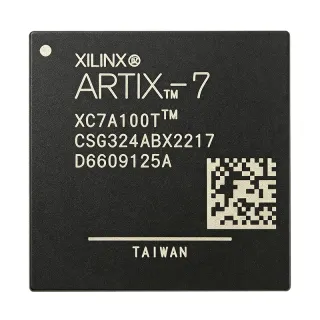
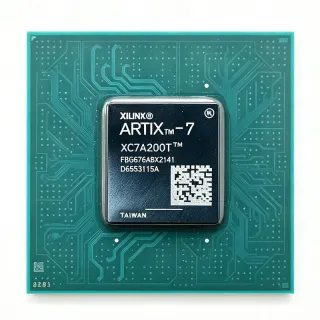
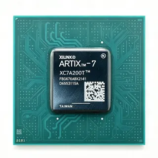
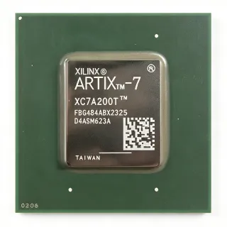
LFE2-35E-6F672I - 32K LUT FPGA, 450 I/O | Lattice Semiconductor
部品番号: LFE2-35E-6F672I ✓ 生産中LFE2-35E-6F672I 概要
An FPGA is a programmable semiconductor that combines configurable logic blocks, programmable interconnect, memory resources, and input/output blocks. The LFE2-35E-6F672I belongs to the ECP2 family and provides a hardware implementation path for designs requiring parallel data processing, protocol bridging, signal conditioning, or high-speed control without relying on a fixed-function ASIC. Its 450 I/O resources make it especially suitable for systems that need substantial external connectivity.
Key features include 32,000 logic elements, 450 user I/O, a 1.2 V operating supply, and a -6 performance designation. The ECP2 architecture is suitable for designs where deterministic parallel logic, flexible configuration, and rapid design changes are more valuable than the power efficiency of a small microcontroller. The 672-ball package supports dense board layouts and high-pin-count implementations.
The LFE2-35E-6F672I is positioned for high-speed digital processing applications. Its 32K logic-element resource enables substantial combinational and sequential logic, while 450 I/O allow multiple buses, control signals, differential interfaces, and peripheral connections to be integrated in one programmable device. The 1.2 V core supply reduces the voltage headroom required by the internal logic fabric.
Typical uses include industrial control systems, communications infrastructure, test and measurement equipment, video and imaging interfaces, embedded signal processing, and high-speed data acquisition. The device can also implement protocol bridges, custom accelerators, control logic, and interface aggregation where firmware flexibility is required.
Designers should verify the exact package ball assignments, pinout, supported I/O standards, configuration method, power-supply sequencing, and board-level thermal conditions in the Lattice ECP2 documentation. Confirm the required speed, temperature, and package variants before releasing a production PCB, especially when using high-speed I/O or differential clocking.
This page combines manufacturer and distributor product information, technical context, application guidance, and drop-in comparison candidates to support component selection and PCB planning.
ドロップイン代替品: LFE2-35E-6F672I — 同一パッケージでピン互換。PCBの作り直しが必要な異なるパッケージの部品は除外されています。
このシリーズのバリエーション
同一シリーズでドロップイン互換のモデル: LFE2-35E-6F672I (同一形状・フットプリント).
LFE2-35SE-6F672I
✅ ドロップイン📋 参考代替品(カタログ未掲載)
LFE2-35E-7F672I
✅ ドロップイン📋 参考代替品(カタログ未掲載)
LFE2-35E-5F672I
✅ ドロップイン価格はお問い合わせください
データシートを見る →LFE2-35E-6FN672I
✅ ドロップイン📋 参考代替品(カタログ未掲載)
LFE2-35E-6F672I 最大定格&電気的特性
| Device Type | ECP2 Field Programmable Gate Array (FPGA) |
| Logic Elements | 32,000 |
| User I/O | 450 I/O |
| Core Supply Voltage | 1.2 V |
| Speed Grade | -6 |
| Temperature Grade | Industrial |
| パッケージ | 672-ball BGA |
| Logic Block Count | 4,000 LABs |
| FPGA Architecture | ECP2 |
| Programmability | SRAM-based configurable logic |
| 実装タイプ | Surface Mount |
| Terminal Type | Ball |
| Number of Terminals | 672 |
| Package Shape | Square |
| RoHS ステータス | Compliant |
| Manufacturer | Lattice Semiconductor Corporation |
| Product Family | ECP2 |
| Primary Logic Use | High-speed digital processing |
LFE2-35E-6F672I square ピン配置ガイド
LFE2-35E-6F672I (square パッケージ) のピン配置。 このデジタルICには、GPIO、通信インターフェース (UART、SPI、I2C)、および電源ピンが含まれています。代替ピン機能と設定オプションについては、メーカーのデータシートを参照してください。組み込みシステム設計とPCBレイアウトに不可欠です。

詳細なピン配置データはありません: LFE2-35E-6F672I.
詳細は データシート をご参照ください。
主な用途
LFE2-35E-6F672I の用途: 6 件s: Industrial Control and Automation, Communications and Protocol Bridging, Test and Measurement Equipment, High-Speed Data Acquisition, Video and Imaging Interfaces, Embedded Signal Processing.
Industrial Control and Automation
The LFE2-35E-6F672I fits industrial controllers that combine machine-control sequencing, sensor conditioning, communication gateways, and safety-adjacent interlocks in one programmable device. Its 32,000 logic elements provide room for parallel control paths and state machines, while 450 I/O can connect digital sensors, actuators, counters, and field-bus transceivers without requiring a large pin-count companion package. The 1.2 V core supply supports compact power architectures, and the -6 speed designation is appropriate for timing-sensitive control logic. For a production design, verify industrial-temperature requirements, differential I/O standards, configuration reliability, and the exact 672-ball footprint in the Lattice ECP2 documentation.
おすすめ
Communications and Protocol Bridging
The LFE2-35E-6F672I is well suited to protocol converters and communications aggregation where several serial interfaces, clock domains, and parallel data paths must operate concurrently. The 32K logic-element capacity can support transmit and receive state machines, buffering, CRC generation, and framing logic, while 450 I/O simplifies connections to transceivers and parallel processors. Its -6 performance grade provides a higher-speed option than the related -5 ECP2 ordering variant for designs needing more timing margin. Validate pin-level interface standards, clock jitter tolerance, board-level signal integrity, and configuration timing before using it in a communications line card.
おすすめ
Test and Measurement Equipment
The LFE2-35E-6F672I can implement custom acquisition, timing, trigger, and pattern-generation logic in test and measurement instruments. Its 450 I/O provides broad connectivity to sensors, ADC and DAC devices, relay drivers, and front-panel controls, while 32,000 logic elements allow multiple processing channels to share one FPGA. The -6 speed grade is useful for timing-critical trigger paths and parallel data movement, and the 1.2 V core supply helps simplify power-tree integration. The design should be reviewed for simulation bandwidth, clock distribution, ground-return paths, thermal margin, and the supported I/O voltage standards for every external device.
おすすめ
High-Speed Data Acquisition
The LFE2-35E-6F672I supports parallel data-acquisition systems where multiple input channels must be sampled, filtered, buffered, and forwarded to a processor or memory. Thirty-two thousand logic elements provide capacity for wide parallel datapaths, digital filtering, and trigger logic, while the 450 available I/O reduce the need for additional multiplexing devices. Its -6 speed grade can improve timing margin over the -5 variant for demanding clock domains. Use careful bank-specific I/O planning, source-synchronous routing, controlled clocking, and matched power distribution so that the FPGA does not become the limiting source of acquisition error.
おすすめ
Video and Imaging Interfaces
The LFE2-35E-6F672I can consolidate timing generation, pixel formatting, synchronization, and interface adaptation in imaging and video-processing equipment. Its 450 I/O is valuable for parallel sensor data, horizontal and vertical synchronization, control signals, and downstream display interfaces, while the 32K logic capacity supports lane alignment and format conversion. The -6 speed grade provides additional timing margin relative to the -5 family option for demanding parallel interfaces. Validate supported I/O standards, clock-domain relationships, lane skew, connector signal integrity, and the exact FPGA configuration method in the target camera or display controller.
おすすめ
Embedded Signal Processing
The LFE2-35E-6F672I is appropriate for custom signal-processing blocks that require deterministic parallel arithmetic, event detection, filtering, or sensor fusion. Its 32,000 logic elements and -6 speed grade support more demanding pipelines than lower-speed ECP2 variants, and its 450 I/O allow parallel sensor data, digital control, and status signaling to coexist. The device can complement a microcontroller or DSP when fixed-latency logic and high I/O density are important. Design the clocking tree conservatively, reserve configuration and programming resources, and use simulation-based timing checks to confirm that all DSP, memory, and external-interface paths meet the system budget.
おすすめ
おすすめ製品の概要
エンジニアリング参考データ: LFE2-35E-6F672I — 比較、設計ガイダンス、コンプライアンス情報。
選定ガイド
代替品との比較
| パラメータ | この製品 | LFE2-35SE-6F672I | LFE2-35E-7F672I | LFE2-35E-5F672I | LFE2-35E-6FN672I |
|---|---|---|---|---|---|
| Package | 672-BBGA | 672-BBGA | 672-BBGA | 672-BBGA | 672-FPBGA |
| Brand | Lattice Semiconductor | Lattice Semiconductor | Lattice Semiconductor | Lattice Semiconductor | Lattice Semiconductor |
| Device Family | ECP2 | ECP2 | ECP2 | ECP2 | ECP2 |
| Logic Elements | 32,000 | 32,000 | 32,000 | 32,000 | 32,000 |
| Logic Blocks | 4,000 LABs | 4,000 LABs | 4,000 LABs | 4,000 LABs | 4,000 LABs |
| User I/O | 450 I/O | 450 I/O | 450 I/O | 450 I/O | 450 I/O |
| Core Supply Voltage | 1.2 V | 1.2 V | 1.2 V | 1.2 V | 1.2 V |
| Speed Grade | -6 | -SE-6 | -7 | -5 | -6 |
| Programmable Resources | 32,000 logic elements and 4,000 LABs | 32,000 logic elements and 4,000 LABs | 32,000 logic elements and 4,000 LABs | 32,000 logic elements and 4,000 LABs | 32,000 logic elements and 4,000 LABs |
| Primary Application | High-speed digital processing | High-speed digital processing | High-speed digital processing | High-speed digital processing | High-speed digital processing |
主な差別化要因
- Balanced logic and I/O capacity (vs LFE2-35E-7F672I)
- Established -6 speed-grade choice (vs LFE2-35E-5F672I)
- Pin-compatible family positioning (vs LFE2-35E-6FN672I)
設計ノート
Treat the 672-ball BGA as a high-density routing problem. Use the Lattice ECP2 package drawing, ball map, and recommended escape-routing pattern before placing decoupling, clock sources, configuration pins, and high-speed interfaces. Preserve the recommended ball and via-array geometry under the FPGA, maintain continuous return paths beneath high-speed nets, and avoid long stubs on sensitive inputs.
The LFE2-35E-6F672I uses a 1.2 V core supply. Follow the ECP2 power-supply sequencing, voltage, noise, and decoupling requirements for the exact device. Place the required bulk and high-frequency capacitors close to their designated supply balls, use multiple power and ground connections as specified, and verify the complete power tree across temperature and FPGA activity. Confirm auxiliary I/O supplies separately rather than assuming they share the core rail.
For high-speed interfaces, assign pins according to the device's supported I/O standards and bank constraints, then use the ECP2 timing and I/O documentation to select drive strength, slew rate, termination, and delay settings. Route clocks as controlled or low-skew nets, provide clean reference planes, and simulate edge rates at the connector or device interface. Verify setup and hold margins after placement, not only in the FPGA timing report.
Do not substitute the -5, -6, -7, -SE, or FN ordering variants solely because their packages appear similar. Confirm the exact logic-resource class, speed grade, temperature grade, package ball map, configuration method, I/O limits, and qualification status. A timing-grade change can alter the available timing margin, while a package or suffix change can affect assembly and qualification even when the broad family name is the same.
FPGA power depends on design utilization, switching activity, I/O loading, and the implemented logic. Obtain the ECP2 power-estimation guidance, enter the actual design activity factors, and size the PCB copper and airflow for the worst specified operating condition. Use thermal sensors or external monitoring where appropriate, and avoid placing the 672-ball device beside heat sources that make board-level temperature difficult to control.
コンプライアンス情報
RoHS compliance is identified for the related LFE2-35E-6FN672I in the ECP2 family documentation. Exact compliance documents for LFE2-35E-6F672I should be confirmed with the manufacturer.