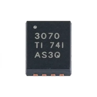
LM2903DGKRG4 - 36V Dual Comparator | Texas Instruments
部品番号: LM2903DGKRG4 ✗ 生産終了LM2903DGKRG4 概要
A voltage comparator is an analog interface that compares two input voltages and produces a logic-level indication of their relationship. The LM2903 belongs to the comparator hierarchy, where a comparator is an analog IC used for threshold detection, signal conditioning, and protection. Its two independent channels can monitor separate control, sensing, or feedback signals, while its open-collector architecture provides flexible interface voltage selection.
The principal operating characteristics include a 2 V to 36 V supply range, approximately 300 ns propagation delay, and low supply-current drain of 0.4 mA typical per comparator. Its rail-to-rail input capability allows the input common-mode range to extend toward the supply rails. Open-collector outputs can sink output current while leaving the effective pull-up voltage under the system designer’s control, making the device useful in wired-AND, wired-OR, and level-shifting arrangements.
Each channel has one inverting input, one non-inverting input, one output, and access to the supply and ground rails. Because the two comparators are independent, each channel can be configured for a different threshold or polarity. Input offset, input bias current, output saturation characteristics, and detailed common-mode behavior should be checked against the manufacturer datasheet for each operating condition, particularly when sensing near a supply rail.
Typical uses include industrial control systems, battery-powered equipment, power-supply sequencing, overvoltage and undervoltage monitoring, sensor-threshold conditioning, and general-purpose logic interfaces. The wide supply range accommodates multiple industrial and automotive-style voltage environments, while the low typical supply-current drain is advantageous in portable systems. An open-collector output also allows multiple comparators to share a pull-up node when wired logic is required.
The primary design consideration is the open-collector output. Every output requires a suitable pull-up resistor and account for sink-current limits, rise time, bus capacitance, and the logic threshold of the receiving device. Input filtering may also be necessary when noisy analog signals are compared, while board placement should keep comparison inputs away from switching nodes and high-current return paths.
This page combines the exact ordering designation with package, pin, application, and drop-in replacement guidance to support schematic review and PCB reuse. It also provides practical design notes for pull-up selection, input conditioning, and open-collector interfacing, helping engineers evaluate the LM2903 family beyond a basic datasheet parameter summary.
ドロップイン代替品: LM2903DGKRG4 — 同一パッケージでピン互換。PCBの作り直しが必要な異なるパッケージの部品は除外されています。
LM2903DGKR
✅ ドロップイン📋 参考代替品(カタログ未掲載)
LM393DGKR
✅ ドロップイン📋 参考代替品(カタログ未掲載)
LM2903B DGKR
✅ ドロップイン📋 参考代替品(カタログ未掲載)
LM293DGKR
✅ ドロップイン📋 参考代替品(カタログ未掲載)
LM2903DGKRG4 最大定格&電気的特性
| Comparator Type | Dual differential comparator |
| Number of Channels | 2 channels |
| Supply Voltage Range | 2 V to 36 V |
| Supply-Span Range for Dual-Supply Operation | 2 V to 36 V |
| Propagation Delay | 300 ns |
| 出力タイプ | Open-collector |
| Input Common-Mode Range | Rail-to-rail |
| Supply Current per Comparator | 0.4 mA typical |
| Maximum Tested Supply Voltage | 30 V |
| パッケージ | 8-VSSOP (8-MSOP, 0.118 inch width) |
| ピン数 | 8 pins |
| 実装タイプ | Surface mount |
| Operating Voltage | 2 V to 36 V |
| Lead Finish | NiPdAu |
| Product Status | Discontinued |
LM2903DGKRG4 ピン構成
| ピン 1 | OUT1 — Comparator 1 open-collector output |
| ピン 2 | IN1- — Comparator 1 inverting input |
| ピン 3 | IN1+ — Comparator 1 non-inverting input |
| ピン 4 | GND — Ground reference |
| ピン 5 | IN2+ — Comparator 2 non-inverting input |
| ピン 6 | IN2- — Comparator 2 inverting input |
| ピン 7 | OUT2 — Comparator 2 open-collector output |
| ピン 8 | VCC — Positive supply |
主な用途
LM2903DGKRG4 の用途: 6 件s: Industrial Threshold Detection, Battery-Powered Condition Monitoring, Power-Supply Sequencing, Sensor Signal Conditioning, Automotive and Heavy Equipment Monitoring, Open-Collector Interface Logic.
Industrial Threshold Detection
The LM2903DGKRG4 fits industrial threshold detection because each of its two independent channels can compare a sensor signal against a reference using a 2 V to 36 V operating range. Place the non-inverting and inverting inputs around the desired switching point, then use the open-collector output to drive a pull-up rail matched to the controller. The approximately 300 ns response class is suitable for many process-control and alarm loops. Designers should still account for input offset near the switching threshold and add filtering when the sensor cable is exposed to industrial noise.
おすすめ
Battery-Powered Condition Monitoring
A battery-powered monitoring design can use the LM2903DGKRG4 to identify voltage thresholds while operating from 2 V to 36 V. Its 0.4 mA typical supply-current drain per comparator supports low-duty-cycle sensing, while the open-collector output allows a low-voltage pull-up to preserve battery energy. The two channels can monitor independent pack or peripheral thresholds and combine through wired logic. During design-in, verify input bias current, comparator behavior as the battery voltage falls, and pull-up power consumption over the complete discharge range.
おすすめ
Power-Supply Sequencing
The LM2903DGKRG4 can supervise power rails because its two independent channels monitor separate supply levels against references. The open-collector outputs permit wired logic for reset, enable, or fault signaling, and the broad 2 V to 36 V supply range supports multiple industrial rail levels. With a pull-up on each output, one channel can indicate an overvoltage condition while the other identifies an undervoltage condition. Ensure that the monitored voltages remain within the comparator input limits and account for output propagation delay when sequencing multiple supplies.
おすすめ
Sensor Signal Conditioning
For sensor signal conditioning, the LM2903DGKRG4 converts a slowly varying analog measurement into an open-collector logic event. The inverting and non-inverting inputs support threshold configurations, and the approximately 300 ns response time provides adequate speed for many temperature, level, and position sensing systems. Keep sensitive inputs short and away from switching power nodes to reduce false switching. If the sensor signal requires amplification, compare the resulting scaled voltage with a stable reference and select resistor values that preserve useful input common-mode range.
おすすめ
Automotive and Heavy Equipment Monitoring
The wide 2 V to 36 V operating range and open-collector interface make the LM2903DGKRG4 suitable for monitoring functions in heavy equipment and automotive-style electrical systems. The comparator can detect battery, generator, or subsystem conditions and report them to a controller through a pull-up network. Because the G4 ordering option is discontinued and qualification details must be checked for the selected assembly configuration, engineers should confirm automotive requirements separately rather than assuming this exact suffix is qualified. Protective filtering and transient control remain necessary in harsh electrical environments.
おすすめ
Open-Collector Interface Logic
The LM2903DGKRG4 is appropriate when several open-collector signals must share a pull-up or interface to a particular logic voltage. Its two outputs can participate in wired-AND or wired-OR arrangements, allowing fault aggregation without adding another logic package. The output polarity is defined by the input connections, so the schematic must clearly identify whether each channel detects a high, low, or overvoltage condition. Select pull-up resistance after considering sink-current capability, rise time, power dissipation, and the capacitance of the connected bus.
おすすめ
おすすめ製品の概要
エンジニアリング参考データ: LM2903DGKRG4 — 比較、設計ガイダンス、コンプライアンス情報。
選定ガイド
代替品との比較
| パラメータ | この製品 | LM2903DGKR | LM393DGKR | LM2903B DGKR | LM293DGKR |
|---|---|---|---|---|---|
| Brand | Texas Instruments | Texas Instruments | Texas Instruments | Texas Instruments | Texas Instruments |
| Package | 8-VSSOP | 8-VSSOP - same | 8-VSSOP - same | 8-VSSOP - same | 8-VSSOP - same |
| Comparator Configuration | Dual differential comparator | Dual differential comparator | Dual differential comparator | Dual differential comparator | Dual differential comparator |
| Propagation Delay | 300 ns | 300 ns | 300 ns | 300 ns | 300 ns |
| Output Type | Open-collector | Open-collector | Open-collector | Open-collector | Open-collector |
主な差別化要因
- Direct same-package consolidation after discontinuation of the G4 suffix (vs LM2903DGKR)
- Two independent channels in a compact surface-mount package (vs LM393DGKR)
- B-series path can improve grade-specific comparator characteristics (vs LM2903B DGKR)
- Wide operating range supports both logic and higher-voltage control rails (vs LM293DGKR)
設計ノート
Do not treat an open-collector output as a actively driven push-pull logic output. Every output requires a pull-up resistor or an existing pull-up elsewhere in the system. Select the resistor to balance output rise time against comparator sink current and resistor power dissipation. For a first-order calculation, use the target logic voltage divided by the required sink current, then verify the resulting rise time against the capacitance of the connected trace and receiver.
Route the two comparator channels with short input traces and a solid ground reference. Keep the inverting and non-inverting traces away from switching nodes, relay contacts, inductors, and high-current return paths. Place any input RC filtering close to the relevant input pin and provide a quiet ground path for the bypass capacitor. This arrangement reduces differential noise pickup and false output transitions near the switching threshold.
Decouple the supply pin locally and account for input transients rather than assuming the wide 2 V to 36 V operating range makes protection unnecessary. Follow the manufacturer’s recommended supply capacitor and place it close to VCC and ground. In systems with long wiring or inductive loads, add appropriate surge and reverse-polarity protection outside the IC, and verify that every protection device remains outside the comparator’s absolute maximum limits.
The approximately 300 ns response time is short enough for many control systems, but open-collector rise time is usually slower because it depends on the pull-up resistor and total bus capacitance. For long traces or slow receivers, calculate the RC rise time and add a suitable pull-up value or buffer. Also account for propagation-delay differences between the two channels when both outputs participate in a timing-sensitive control or protection sequence.
コンプライアンス情報
The G4 ordering option is documented as using a NiPdAu lead finish and all products are described as green, but no formal RoHS, REACH, AEC-Q100, halogen-free, or conflict-minerals declarations are included in the product material. The obsolete G4 ordering suffix was removed to consolidate part-number options.