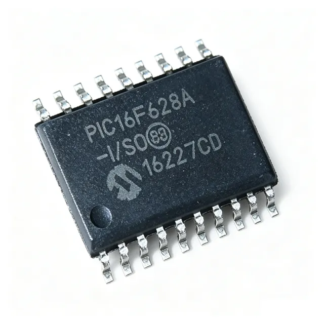
PIC16F628A-I/SO - 8-bit 20MHz 3.5KB Flash MCU | Microchip
部品番号: PIC16F628A-I/SO ✓ 生産中| 数量 | 単価 | 小計 |
|---|---|---|
| 1 | $3.5 | $3.50 |
| 10 | $3.15 | $31.50 |
| 100 | $2.8 | $280.00 |
| 500 | $2.55 | $1,275.00 |
| 1,000 | $2.32 | $2,320.00 |
PIC16F628A-I/SO 概要
An 8-bit microcontroller is a single-chip computer that fetches 8-bit-wide data over an 8-bit internal data path while typically using a wider instruction word. The PIC16F628A uses a 14-bit-wide Harvard instruction word, meaning instructions and data travel on separate buses so the CPU can prefetch the next instruction while completing the current one. Within the broader taxonomy, this part sits at: PIC16F628A -> PIC16F62x family -> PIC16 enhanced mid-range MCU -> 8-bit microcontroller -> Microcontroller (MCU) -> Integrated Circuit. The 'F' suffix indicates Flash program memory, allowing in-circuit serial programming via ICSP for prototyping and field updates.
Key differentiating features include nanoWatt power management with multiple idle/sleep modes that drop supply current to the low-microamp range, an internal 4 MHz oscillator accurate enough for UART baud generation without external timing components, two comparators with programmable references that implement op-amp-like analog signal conditioning without external ICs, and a USART for asynchronous serial communication. The 'I' suffix indicates the industrial operating-temperature grade of -40 °C to +85 °C, while the 'SO' suffix denotes the 18-pin 7.5 mm SOIC plastic package.
Architecturally, the part implements a RISC-style instruction set of 35 single-word instructions, an eight-level deep hardware stack, and direct/indirect addressing modes with a single-cycle multiplication assist. The integrated peripherals are mapped through a linear I/O register map that simplifies C and assembly firmware development in MPLAB X with the XC8 compiler.
Typical applications include automotive body and convenience modules, white-goods and appliance control boards, security and access-control panels, low-end consumer electronics, hobby projects, and any battery-powered sensor node that benefits from the nanoWatt sleep modes. The wide 4.5 V to 5.5 V supply range and integrated analog comparators make it equally at home in industrial sensor-interface designs.
When designing with this MCU, reserve the ICSPDAT/ICSPCLK pins (RB6/RB7) for the in-circuit serial programming header so the device can be re-flashed on the assembled PCB. Place a 0.1 µF decoupling capacitor within 5 mm of VDD, keep analog comparator inputs short, and avoid toggling the MCLR pin while programming. For the 4 MHz internal oscillator, verify UART baud-rate error against the chosen BAUD value before relying on asynchronous serial links.
This page synthesizes verified distributor pricing, pin-compatible drop-in alternatives sourced from Microchip's own cross-reference and FindMyChip, and practical design notes that complement the manufacturer datasheet.
ドロップイン代替品: PIC16F628A-I/SO — 同一パッケージでピン互換。PCBの作り直しが必要な異なるパッケージの部品は除外されています。
このシリーズのバリエーション
同一シリーズでドロップイン互換のモデル: PIC16F628A-I/SO (同一形状・フットプリント) — 相違点: Program Memory Size, Package, Program Memory Type, RAM Size, Instruction Cycle Time.
クイック比較ツール — 並列比較する代替部品を選択:
PIC16F628A-I/P
✓ 在庫あり
$1.62 / 個
データシートを見る →PIC16F648A-I/SO
✓ 在庫あり
$2.1 / 個
データシートを見る →PIC16F627A-I/SO
✓ 在庫あり
$1.74 / 個
データシートを見る →PIC16F628-04I/SO
✓ 在庫あり
$2.3 / 個
データシートを見る →PIC16F628-20E/SO
✓ 在庫あり
$2.55 / 個
データシートを見る →PIC16F628-20/P
✓ 在庫あり
$1.96 / 個
データシートを見る →PIC16F628A-I/SO 最大定格&電気的特性
| Core Processor | PIC16F |
| Core Size | 8-bit |
| Maximum Clock Speed | 20 MHz |
| Program Memory Size | 3.5 KB (2K x 14) Flash |
| RAM Size | 224 bytes |
| EEPROM Size | 128 x 8 bytes |
| Number of I/O Pins | 16 |
| Supply Voltage (Vdd) | 4.5 V to 5.5 V |
| Internal Oscillator | 4 MHz (calibrated) |
| Peripherals | Brown-out Detect, POR, PWM, WDT, USART, 2 Comparators |
| Programmable Voltage Reference | Yes (shared with comparators) |
| 動作温度 | -40 °C to +85 °C (Industrial, 'I' suffix) |
| パッケージ | 18-SOIC (0.295", 7.50 mm) |
| 実装タイプ | Surface Mount |
| Instruction Set | 35 instructions, 14-bit word |
| Instruction Cycle | 200 ns @ 20 MHz |
| Hardware Stack | 8 levels |
| MSLレベル | 1 |
| RoHS ステータス | Compliant |
| ICSP (In-Circuit Serial Programming) | Yes |
PIC16F628A-I/SO ピン構成
| ピン 1 | RA2/AN2/CVREF/VREF — Port A bit 2; analog channel 2; comparator reference output; voltage reference output |
| ピン 2 | RA3/AN3/C1OUT — Port A bit 3; analog channel 3; comparator 1 output |
| ピン 3 | RA4/AN4/T0CKI — Port A bit 4; analog channel 4; Timer 0 clock input |
| ピン 4 | RA5/MCLR/VPP — Port A bit 5; Master Clear reset (active low); programming voltage input |
| ピン 5 | VSS — Ground reference |
| ピン 6 | RB0/INT — Port B bit 0; external interrupt input |
| ピン 7 | RB1/RX/DT — Port B bit 1; USART receive / synchronous data |
| ピン 8 | RB2/TX/CK — Port B bit 2; USART transmit / synchronous clock |
| ピン 9 | RB3/CCP1 — Port B bit 3; Capture/Compare/PWM 1 |
| ピン 10 | RB4/PGM — Port B bit 4; Low-voltage programming input |
| ピン 11 | RB5 — Port B bit 5 |
| ピン 12 | RB6/ICSPCLK/T1OSO — Port B bit 6; ICSP clock; Timer 1 oscillator output |
| ピン 13 | RB7/ICSPDAT/T1OSI — Port B bit 7; ICSP data; Timer 1 oscillator input |
| ピン 14 | VDD — Positive supply voltage (4.5 V to 5.5 V) |
| ピン 15 | OSC2/CLKOUT/RA6 — Oscillator output / clock output / Port A bit 6 |
| ピン 16 | OSC1/CLKIN/RA7 — Oscillator input / clock input / Port A bit 7 |
| ピン 17 | RA0/AN0 — Port A bit 0; analog channel 0; comparator 1 negative input |
| ピン 18 | RA1/AN1 — Port A bit 1; analog channel 1; comparator 2 negative input |
主な用途
PIC16F628A-I/SO の用途: 7 件s: White-Goods and Appliance Control, Automotive Body and Convenience Modules, Security and Access-Control Panels, Battery-Powered Sensor Nodes, Hobby Electronics and Educational Kits, Industrial Sensor Interfaces, Consumer Audio and IR Remote Controllers.
White-Goods and Appliance Control
The PIC16F628A-I/SO is a workhorse MCU for washing machines, dishwashers, microwave ovens, and induction-cooktop UI boards. Its 16 I/O pins drive relay triacs, seven-segment displays, and keypads; the 20 MHz CPU executes closed-loop control at sub-millisecond intervals. The integrated 4 MHz internal oscillator eliminates the external crystal, reducing BOM cost in price-sensitive appliances. Two comparators with programmable voltage references implement zero-crossing detection and water-level sensing without external op-amps.
おすすめ
Automotive Body and Convenience Modules
The PIC16F628A-I/SO is used in interior lighting controllers, central-locking modules, and aftermarket alarm panels. The industrial-grade -40 °C to +85 °C range covers most cabin temperatures, and the brown-out reset prevents corruption when the vehicle battery sags during cranking. The PWM module drives LED current at constant luminance, while the USART links to body-control modules via LIN transceivers. For AEC-Q100 requirements, designers should evaluate the automotive-grade PIC16F K-series equivalents from Microchip.
おすすめ
Security and Access-Control Panels
Alarm panels, keypad entry controllers, and PIR-sensor nodes leverage the PIC16F628A-I/SO's low-power nanoWatt modes and 128 bytes of EEPROM for credential storage. The two analog comparators sense PIR amplifier outputs without external op-amps, while the USART links to GSM or Wi-Fi alarm-reporting modules. EEPROM endurance of 1M write cycles supports frequent credential updates. The SOIC-18 footprint enables compact SMD assembly for retrofit IoT bridge products.
おすすめ
Battery-Powered Sensor Nodes
Remote sensors, irrigation controllers, and battery-powered industrial gauges benefit from the PIC16F628A-I/SO's nanoWatt sleep mode, which drops supply current to under 1 µA. The internal 4 MHz oscillator wakes the MCU in microseconds, eliminating crystal warm-up latency. The 16-bit timers with capture registers measure pulse widths from flow meters and ultrasonic sensors, while EEPROM stores calibration constants across sleep cycles. Solar and battery-backed designs use the brown-out reset to ride out low-voltage conditions.
おすすめ
Hobby Electronics and Educational Kits
The PIC16F628A-I/SO remains a favorite for hobbyists, robotics clubs, and university embedded courses. The 35-instruction RISC set is teachable in a single lab session, and the SOIC-18 footprint is breadboardable with low-cost adapter PCBs. ICSP lets students re-flash the MCU without removing it from the breadboard, supporting iterative learning. The 20 MHz headroom teaches real-time scheduling and interrupt-driven design without requiring advanced ARM toolchains.
おすすめ
Industrial Sensor Interfaces
In factory-floor PLCs, signal conditioners, and discrete I/O modules, the PIC16F628A-I/SO serves as a low-cost signal-translation MCU. Its two comparators with programmable voltage references implement window comparators for 4-20 mA current-loop sensing, while the USART bridges to Modbus RTU networks via RS-485 transceivers. The PWM module synthesizes analog output voltages from a digital reference. Industrial temperature grade and ICSP field-flash extend the part's lifecycle in 24/7 deployments.
おすすめ
Consumer Audio and IR Remote Controllers
Universal remote controls, IR-to-Bluetooth bridge dongles, and consumer audio accessories fit the PIC16F628A-I/SO's profile. The 20 MHz CPU generates precise IR carrier frequencies for RC5, NEC, and SIRC protocols, and the PWM module produces 38 kHz subcarriers without external timers. The USART interfaces with Bluetooth HC-05-class modules, while EEPROM stores learned IR codes. The SOIC-18 package is friendly to high-volume SMD production lines.
おすすめ
おすすめ製品の概要
エンジニアリング参考データ: PIC16F628A-I/SO — 比較、設計ガイダンス、コンプライアンス情報。
選定ガイド
代替品との比較
| パラメータ | この製品 | PIC16F628A-I/P | PIC16F648A-I/SO | PIC16F627A-I/SO | PIC16F628-04I/SO |
|---|---|---|---|---|---|
| Brand | Microchip Technology | Microchip Technology | Microchip Technology | Microchip Technology | Microchip Technology |
| Package | 18-SOIC | 18-PDIP (different) | 18-SOIC (same) | 18-SOIC (same) | 18-SOIC (same) |
| Flash Program Memory | 3.5 KB (2K x 14) | 3.5 KB (2K x 14) | 8 KB (4K x 14) | 1.75 KB (1K x 14) | 3.5 KB (2K x 14) |
| RAM | 224 B | 224 B | 256 B | 224 B | 224 B |
| EEPROM | 128 B | 128 B | 128 B | 128 B | 128 B |
| Maximum Clock Frequency | 20 MHz | 20 MHz | 20 MHz | 20 MHz | 4 MHz |
| Operating Temperature | -40 °C to +85 °C (I) | -40 °C to +85 °C (I) | -40 °C to +85 °C (I) | -40 °C to +85 °C (I) | -40 °C to +85 °C (I) |
| I/O Pins | 16 | 16 | 16 | 16 | 16 |
| Peripherals (USART/PWM/Comparators) | USART, PWM, 2x Comparators | Identical | Identical | Identical | Identical |
主な差別化要因
- Calibrated 4 MHz internal oscillator enables crystal-less UART operation (vs PIC16F628-04I/SO)
- 3.5 KB Flash hits the sweet spot between cost and capability (vs PIC16F627A-I/SO (1.75 KB) and PIC16F648A-I/SO (8 KB))
- Industrial -40 °C to +85 °C temperature grade (vs PIC16F628-20/P (commercial 0 °C to +70 °C))
- Surface-mount SOIC-18 footprint for high-volume production (vs PIC16F628A-I/P (18-pin PDIP through-hole))
設計ノート
Add a 0.1 µF ceramic decoupling capacitor within 5 mm of the VDD pin (pin 14) and a 10 µF bulk capacitor on the supply rail. Brown-out reset is included, but place a TVS diode on VDD for industrial environments with inductive loads. The MCU draws less than 1 µA in sleep mode, so a backup supercapacitor can retain RTC state across power cycles.
Reserve RB6 (pin 12) and RB7 (pin 13) for the ICSP header alongside MCLR, VDD, and VSS. Keep the ICSP traces short and away from switching nodes to avoid programming noise. Route the analog comparator inputs (RA0-RA3) over a quiet ground plane and keep them short to prevent switching-noise coupling that would degrade comparator threshold accuracy.
When using the internal 4 MHz oscillator with the USART, validate UART baud-rate error against the chosen SPBRG value before relying on asynchronous serial. For higher baud rates (above 57600) or stricter error budgets, switch to an external crystal on OSC1/OSC2 (pins 16/15). The PWM output on RB3 (CCP1) is robust to 20 mA but should still be buffered when driving power FETs.
Do not leave MCLR floating; tie it to VDD through a 10 kΩ resistor with a 100 nF capacitor to ground for noise filtering. Avoid powering the MCU below 4.5 V or above 5.5 V - the brown-out reset is calibrated for this window. When programming via ICSP, ensure the MCLR pull-up is strong enough to keep VPP within the high-voltage range during programming but not so strong that it fights the programmer.
Estimated: at 20 MHz clock and full peripheral activity, the PIC16F628A-I/SO consumes approximately 8 mA from 5 V (about 40 mW). The 18-SOIC package has a theta_JA around 100 °C/W on a 1 oz copper 2-layer board, so the junction temperature rise is under 4 °C above ambient at this power level. No heatsink is required; provide adequate copper pour for production boards.
コンプライアンス情報
RoHS compliant per Microchip product page. 'I' suffix denotes industrial temperature grade -40 °C to +85 °C, not AEC-Q100. Choose 'A' suffix or automotive-grade PIC16F K-series for AEC-Q100 applications.







